EP0355878A1 - Construction de jonction et disposition de montage - Google Patents
Construction de jonction et disposition de montage Download PDFInfo
- Publication number
- EP0355878A1 EP0355878A1 EP89201770A EP89201770A EP0355878A1 EP 0355878 A1 EP0355878 A1 EP 0355878A1 EP 89201770 A EP89201770 A EP 89201770A EP 89201770 A EP89201770 A EP 89201770A EP 0355878 A1 EP0355878 A1 EP 0355878A1
- Authority
- EP
- European Patent Office
- Prior art keywords
- nut
- stud
- socket
- cam ring
- locking disk
- Prior art date
- Legal status (The legal status is an assumption and is not a legal conclusion. Google has not performed a legal analysis and makes no representation as to the accuracy of the status listed.)
- Withdrawn
Links
Images

Classifications
-
- F—MECHANICAL ENGINEERING; LIGHTING; HEATING; WEAPONS; BLASTING
- F16—ENGINEERING ELEMENTS AND UNITS; GENERAL MEASURES FOR PRODUCING AND MAINTAINING EFFECTIVE FUNCTIONING OF MACHINES OR INSTALLATIONS; THERMAL INSULATION IN GENERAL
- F16B—DEVICES FOR FASTENING OR SECURING CONSTRUCTIONAL ELEMENTS OR MACHINE PARTS TOGETHER, e.g. NAILS, BOLTS, CIRCLIPS, CLAMPS, CLIPS OR WEDGES; JOINTS OR JOINTING
- F16B7/00—Connections of rods or tubes, e.g. of non-circular section, mutually, including resilient connections
- F16B7/18—Connections of rods or tubes, e.g. of non-circular section, mutually, including resilient connections using screw-thread elements
-
- F—MECHANICAL ENGINEERING; LIGHTING; HEATING; WEAPONS; BLASTING
- F16—ENGINEERING ELEMENTS AND UNITS; GENERAL MEASURES FOR PRODUCING AND MAINTAINING EFFECTIVE FUNCTIONING OF MACHINES OR INSTALLATIONS; THERMAL INSULATION IN GENERAL
- F16B—DEVICES FOR FASTENING OR SECURING CONSTRUCTIONAL ELEMENTS OR MACHINE PARTS TOGETHER, e.g. NAILS, BOLTS, CIRCLIPS, CLAMPS, CLIPS OR WEDGES; JOINTS OR JOINTING
- F16B13/00—Dowels or other devices fastened in walls or the like by inserting them in holes made therein for that purpose
- F16B13/04—Dowels or other devices fastened in walls or the like by inserting them in holes made therein for that purpose with parts gripping in the hole or behind the reverse side of the wall after inserting from the front
- F16B13/08—Dowels or other devices fastened in walls or the like by inserting them in holes made therein for that purpose with parts gripping in the hole or behind the reverse side of the wall after inserting from the front with separate or non-separate gripping parts moved into their final position in relation to the body of the device without further manual operation
- F16B13/0866—Dowels or other devices fastened in walls or the like by inserting them in holes made therein for that purpose with parts gripping in the hole or behind the reverse side of the wall after inserting from the front with separate or non-separate gripping parts moved into their final position in relation to the body of the device without further manual operation with prongs penetrating into the wall of the hole by a retractile movement of a threaded member
-
- F—MECHANICAL ENGINEERING; LIGHTING; HEATING; WEAPONS; BLASTING
- F16—ENGINEERING ELEMENTS AND UNITS; GENERAL MEASURES FOR PRODUCING AND MAINTAINING EFFECTIVE FUNCTIONING OF MACHINES OR INSTALLATIONS; THERMAL INSULATION IN GENERAL
- F16B—DEVICES FOR FASTENING OR SECURING CONSTRUCTIONAL ELEMENTS OR MACHINE PARTS TOGETHER, e.g. NAILS, BOLTS, CIRCLIPS, CLAMPS, CLIPS OR WEDGES; JOINTS OR JOINTING
- F16B39/00—Locking of screws, bolts or nuts
- F16B39/22—Locking of screws, bolts or nuts in which the locking takes place during screwing down or tightening
- F16B39/28—Locking of screws, bolts or nuts in which the locking takes place during screwing down or tightening by special members on, or shape of, the nut or bolt
-
- F—MECHANICAL ENGINEERING; LIGHTING; HEATING; WEAPONS; BLASTING
- F16—ENGINEERING ELEMENTS AND UNITS; GENERAL MEASURES FOR PRODUCING AND MAINTAINING EFFECTIVE FUNCTIONING OF MACHINES OR INSTALLATIONS; THERMAL INSULATION IN GENERAL
- F16B—DEVICES FOR FASTENING OR SECURING CONSTRUCTIONAL ELEMENTS OR MACHINE PARTS TOGETHER, e.g. NAILS, BOLTS, CIRCLIPS, CLAMPS, CLIPS OR WEDGES; JOINTS OR JOINTING
- F16B41/00—Measures against loss of bolts, nuts, or pins; Measures against unauthorised operation of bolts, nuts or pins
- F16B41/002—Measures against loss of bolts, nuts or pins
-
- F—MECHANICAL ENGINEERING; LIGHTING; HEATING; WEAPONS; BLASTING
- F16—ENGINEERING ELEMENTS AND UNITS; GENERAL MEASURES FOR PRODUCING AND MAINTAINING EFFECTIVE FUNCTIONING OF MACHINES OR INSTALLATIONS; THERMAL INSULATION IN GENERAL
- F16B—DEVICES FOR FASTENING OR SECURING CONSTRUCTIONAL ELEMENTS OR MACHINE PARTS TOGETHER, e.g. NAILS, BOLTS, CIRCLIPS, CLAMPS, CLIPS OR WEDGES; JOINTS OR JOINTING
- F16B7/00—Connections of rods or tubes, e.g. of non-circular section, mutually, including resilient connections
- F16B7/04—Clamping or clipping connections
- F16B7/0406—Clamping or clipping connections for rods or tubes being coaxial
- F16B7/0413—Clamping or clipping connections for rods or tubes being coaxial for tubes using the innerside thereof
-
- F—MECHANICAL ENGINEERING; LIGHTING; HEATING; WEAPONS; BLASTING
- F16—ENGINEERING ELEMENTS AND UNITS; GENERAL MEASURES FOR PRODUCING AND MAINTAINING EFFECTIVE FUNCTIONING OF MACHINES OR INSTALLATIONS; THERMAL INSULATION IN GENERAL
- F16B—DEVICES FOR FASTENING OR SECURING CONSTRUCTIONAL ELEMENTS OR MACHINE PARTS TOGETHER, e.g. NAILS, BOLTS, CIRCLIPS, CLAMPS, CLIPS OR WEDGES; JOINTS OR JOINTING
- F16B9/00—Connections of rods or tubular parts to flat surfaces at an angle
- F16B9/05—Connections of rods or tubular parts to flat surfaces at an angle by way of an intermediate member
- F16B9/054—Connections of rods or tubular parts to flat surfaces at an angle by way of an intermediate member the intermediate member being threaded
-
- F—MECHANICAL ENGINEERING; LIGHTING; HEATING; WEAPONS; BLASTING
- F21—LIGHTING
- F21V—FUNCTIONAL FEATURES OR DETAILS OF LIGHTING DEVICES OR SYSTEMS THEREOF; STRUCTURAL COMBINATIONS OF LIGHTING DEVICES WITH OTHER ARTICLES, NOT OTHERWISE PROVIDED FOR
- F21V21/00—Supporting, suspending, or attaching arrangements for lighting devices; Hand grips
- F21V21/02—Wall, ceiling, or floor bases; Fixing pendants or arms to the bases
- F21V21/03—Ceiling bases, e.g. ceiling roses
-
- F—MECHANICAL ENGINEERING; LIGHTING; HEATING; WEAPONS; BLASTING
- F16—ENGINEERING ELEMENTS AND UNITS; GENERAL MEASURES FOR PRODUCING AND MAINTAINING EFFECTIVE FUNCTIONING OF MACHINES OR INSTALLATIONS; THERMAL INSULATION IN GENERAL
- F16B—DEVICES FOR FASTENING OR SECURING CONSTRUCTIONAL ELEMENTS OR MACHINE PARTS TOGETHER, e.g. NAILS, BOLTS, CIRCLIPS, CLAMPS, CLIPS OR WEDGES; JOINTS OR JOINTING
- F16B2200/00—Constructional details of connections not covered for in other groups of this subclass
- F16B2200/40—Clamping arrangements where clamping parts are received in recesses of elements to be connected
- F16B2200/403—Threaded clamping parts
-
- F—MECHANICAL ENGINEERING; LIGHTING; HEATING; WEAPONS; BLASTING
- F16—ENGINEERING ELEMENTS AND UNITS; GENERAL MEASURES FOR PRODUCING AND MAINTAINING EFFECTIVE FUNCTIONING OF MACHINES OR INSTALLATIONS; THERMAL INSULATION IN GENERAL
- F16B—DEVICES FOR FASTENING OR SECURING CONSTRUCTIONAL ELEMENTS OR MACHINE PARTS TOGETHER, e.g. NAILS, BOLTS, CIRCLIPS, CLAMPS, CLIPS OR WEDGES; JOINTS OR JOINTING
- F16B2200/00—Constructional details of connections not covered for in other groups of this subclass
- F16B2200/40—Clamping arrangements where clamping parts are received in recesses of elements to be connected
- F16B2200/406—Clamping parts being collars, bushings or wedges
-
- Y—GENERAL TAGGING OF NEW TECHNOLOGICAL DEVELOPMENTS; GENERAL TAGGING OF CROSS-SECTIONAL TECHNOLOGIES SPANNING OVER SEVERAL SECTIONS OF THE IPC; TECHNICAL SUBJECTS COVERED BY FORMER USPC CROSS-REFERENCE ART COLLECTIONS [XRACs] AND DIGESTS
- Y10—TECHNICAL SUBJECTS COVERED BY FORMER USPC
- Y10T—TECHNICAL SUBJECTS COVERED BY FORMER US CLASSIFICATION
- Y10T403/00—Joints and connections
- Y10T403/70—Interfitted members
- Y10T403/7047—Radially interposed shim or bushing
- Y10T403/7051—Wedging or camming
- Y10T403/7052—Engaged by axial movement
- Y10T403/7056—Threaded actuator
-
- Y—GENERAL TAGGING OF NEW TECHNOLOGICAL DEVELOPMENTS; GENERAL TAGGING OF CROSS-SECTIONAL TECHNOLOGIES SPANNING OVER SEVERAL SECTIONS OF THE IPC; TECHNICAL SUBJECTS COVERED BY FORMER USPC CROSS-REFERENCE ART COLLECTIONS [XRACs] AND DIGESTS
- Y10—TECHNICAL SUBJECTS COVERED BY FORMER USPC
- Y10T—TECHNICAL SUBJECTS COVERED BY FORMER US CLASSIFICATION
- Y10T403/00—Joints and connections
- Y10T403/70—Interfitted members
- Y10T403/7047—Radially interposed shim or bushing
- Y10T403/7061—Resilient
Definitions
- This invention relates to a joint construction between two members, a first of which includes a socket, and in particular to a joint construction including an expansion connector assembly carried by the second member that is merely plugged into the socket and then rotated, to provide a strong and firm connection between the two members.
- This type of connector comprises a first part which is in the nature of an insert and a second part which includes a socket for the insert.
- the insert is inserted into the socket and expanded to exert a clamping or holding force on the wall of the socket.
- expansion connectors which can be found in the patent literature are shown by the following United States patents: No. 2,190,555, granted February 13, 1940, to Charles A. Toce, Robert F. Broussard and William N. Woodruff; No. 2,281,279, granted April 28, 1942, to David A. Fox; No. 2,798,748, granted July 9, 1957, to Albrecht Maurer; No. 3,009,747, granted November 21, 1961, to Kenneth H. Pitzer; No. 3,135,033, granted June 2, 1964, to Samuel H. Jackson; No. 3,355,201, granted November 28, 1967 to Leroy E. Barwick; No. 3,779,659, granted December 18, 1973 to Roger Habert; and No. 4,134,703, granted January 16, 1979, to Earl S. Hinners. Other expansion connectors are disclosed by my United States patents No. 4,667,916 and No. 4,691,889.
- the present invention relates to the provision of a new and unique joint construction comprising a first member which includes an expansion insert.
- the insert is merely slipped endwise into a socket carried by the second member, and then one of the members is simply rotated relative to the other, and the insert functions to dig into the wall of the socket and in that manner securely connect the two members together.
- Another object of the invention is to provide an improved mounting structure for a suspended object (e.g. a lighting fixture) which utilizes the joint construction, and which makes it possible for the user to disassemble and then later reassemble the mounting structure, without the use of destructive methods (e.g. removing parts by use of metal cutting equipment).
- a suspended object e.g. a lighting fixture
- destructive methods e.g. removing parts by use of metal cutting equipment
- the mounting structure of the present invention provides a way of easily connecting and disconnecting the parts of the mounting structure to each other and to the ceiling structure, so that if it becomes necessary to remove the mounting structure, it can be done without destructive affects to this component, so that such component can be reused.
- the mounting structure of the present invention makes it easy to raise or lower a lighting fixture or similar object.
- the mounting structure need only be disassembled and then reassembled with a longer or shorter support leg.
- the joint construction of the present invention comprises a first member which includes a cylindrical sidewall defining a socket having an inner surface, and a second member which includes a connector assembly that plugs into the socket.
- the connector assembly comprises a fixed in position threaded stud having a base and a free end.
- a lower locking disk is provided at the base of the stud.
- the lower locking disk includes a central opening through which the stud extends, and a plurality of wings spaced around the disk and formed to extend away from the base of the stud.
- a cam ring is provided having a central opening through which the stud extends and having upper and lower outer beveled edges at opposite ends. The cam ring is smaller in diameter than the inside diameter of the socket.
- At least one upper locking disk is located on the stud.
- Each upper locking disk includes a central opening through which the stud extends, and a plurality of wings spaced around the disk and formed toward the upper beveled edge of the cam ring.
- the wings have outer grip edges.
- Each locking disk is sized to slip fit into the socket.
- a nut is threaded onto the stud, outwardly of the upper locking disk(s).
- the nut may include a flange at its end nearest the cam ring and a wrench portion extending from said flange in a direction opposite the cam ring.
- a nut wing washer is secured to the nut.
- the nut wing washer has a central opening corresponding in shape to the wrench portion on the nut in which the wrench portion of the nut is received.
- the nut wing washer has a plurality of wings which are bent to extend toward the cam ring.
- the wings have grip edges at their outer ends. It also has a plan form that is larger than the inside diameter of said socket.
- the two members are easily and quickly connected together by a slip-in movement of the connector assembly on the second member into the tubular socket of the first member.
- This slip-in movement causes a bending of the wings of the nut wing washer, attended by the edges of such wings gripping the inner surface of the socket.
- one of the members is rotated relative to the other.
- the grip of the edges of the wings of the nut wing washer holds the nut wing washer against rotation relative to the socket.
- the nut wing washer is secured against rotation to the nut, and so the nut also is held in position relative to the first member during the rotation.
- there is an axial travel of the nut on the stud toward the cam ring Such axial travel causes the beveled edges of the cam ring to push the wings of the upper and lower lock disks outwardly, so as to press their edges into tight galling engagement with the inner surface of the socket.
- a joint construction of the type described above is provided at the lower end of a support leg.
- the connector assembly is a part of a frame member which is connected to the lower end of the support leg.
- the upper end of the support leg is connected to an overhead structure, such as a ceiling, or the like.
- this mounting structure is used for suspending an object from the overhead of the ship.
- the upper end of the support leg is secured to a portion of the ceiling and the frame member is attached to the lower end of the support leg, in the manner described above.
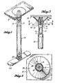
- Figs. 1-7 illustrate a preferred form of overhead support member and a preferred form of joint construction.
- member 10 is an overhead structure.
- Member 10 includes a downwardly extending threaded stud 12 (Fig. 2).
- a mounting leg 14 includes an insert member 16 at its upper end.
- Member 16 includes a threaded axial opening 18.
- the upper end portion of support leg 14 may be swaged about the insert 16, for firmly gripping the diameter interior opening 20 through which the insert 16 cannot pass in the upward direction.
- the portion of support leg 14 below insert 16 is preferrably swaged to provide a cross section which includes at least one pair of opposed wrench flats 15.
- the illustrated example includes a second pair of wrench flats 17.
- a reduced diameter section below the insert 16 prevents downward movement of insert 16.
- a flat rectangular bar 22 is provided at the lower end of support leg 14.
- Bar 22 carries a connector assembly 24 which can be easily moved endwise into the tubular lower end portion 26 of the support leg 14.
- the connector assembly 24 comprises a stud 28 having a base end 30 which is shown connected to the member 22.
- the stud 28 is in the form of a bolt having a head 32 at its lower end.
- the square shank base of the bolt 28′ extends through a square opening 34 formed in member 22.
- a lower locking disk 44′ At the base end of the stud 28 is a lower locking disk 44′.
- the lower locking disk 44′ has a circular opening 56′ at its center through which the stud 28 extends.
- a washer 39 sized larger than the diameter of the tubular portion 26 of the support leg 14, may be provided between the lower locking disk 44 and the upper surface of member 22.
- a cam ring 36 is provided upwardly of the lower locking disk 44′.
- the stud 28 extends upwardly through a central opening 42 in the cam ring 36.
- Opposite outward edges 40, 40′ are beveled, as illustrated. These upper and lower edges 40, 40′ constitute cam surfaces, the function of which will hereinafter be described.
- one or more upper locking disks 44 are stacked on the stud 28. Three such upper locking discs 44 are shown in Figs. 4, 5 and 7.
- a nut 46 is provided above the upper locking disk(s) 44.
- Nut 46 includes a flange 48 at its lower end, down onto which the central portion of a nut wing washer 50 sits.
- the illustrated nut 46 has a wrench flat portion 52 of conventional hexagonal form.
- the nut wing washer 50 includes a central opening 54 which is sized to snugly receive the hexagonal wrench flat portion 42.
- the nut wing washer 50 sits down on the flange 48 and such flange 48 prevents it from moving axially in the downward direction.
- upper corner portions of the nut 46 are deformed to form projections 55 which serve to prevent the nut wing washer 50 from moving off the nut in the direction away from flange 48.
- the lock disks 44, 44′ have circular openings 56, 56′ at their centers through which the threaded shank portion of the stud 28 extends.
- the nut wing washer 50 and the locking disks 44, 44′ have winged portions which are bent at an angle to a flat central portion.
- the winged portions 66′ of the lower locking disk 44′ are bent upwardly at an angle away from member 22.
- Winged portions 66 of the upper locking disks 44 and wings 58 of the nut wing washer 50 are bent downwardly toward member 22. In this manner, winged portions 66, 66′ of the locking disks 44, 44′ are angled toward the cam ring 36 which is situated therebetween.
- the outer edges of the wings 58 may be cut to each comprise a point on each side and a concave region between the points, as illustrated.
- This nut wing washer 50 is slightly larger in diameter than the inside diameter of the tubular end portion 26 of member 14.
- the nut wing washer 50 may be constructed from a thinner material than the main locking disks 44, for reasons to be hereinafter explained.
- each upper locking disk 44 includes three wings 66 equally spaced about the locking disk 44.
- Each wing 66 forms a dihedral with a flat central portion 68.
- Fold lines 69 give the central portion 68 a generally triangular shape.
- the outer edges 70 of the wings 44 may be plain or serrated. The plain form is illustrated.
- the edges 70 lie on circles having their center at the center 72 of opening 56.
- the circle on which the edges 70 lie is either substantially equal to or slightly less in diameter than the inside diameter of the tubular end portion 26 of member 14, so that the main lock discs will not interfere with easy insertion of the connector assembly into the socket 26. Easy insertion is the key factor.
- the lower locking disk 44′ is essentially identical to the upper locking disk 44 except that the winged portions 66 are bent upwardly.
- the connector assembly is assembled as follows.
- the stud 28 is connected to the member 22, such as by making stud 28 in the form of a bolt.
- the washer 39 is then installed onto the stud 28.
- a lower locking disk 44′ is placed onto the stud 28 with winged portions 66′ directed upwardly.
- the cam ring 36 is placed on the stud 28 above the lower locking disk 44′.
- the upper locking disk(s) 44 is placed onto the stud 28 with wings 66 extending downwardly toward the cam 36.
- the nut 46 (with nut wing washer 50 attached) is installed and is screwed down until it contacts the upper locking disc 44 (or the top upper locking disk 44 in a stack).
- the upper or free end of the stud 28 may be spread or otherwise deformed, as shown by Figs. 4 and 7, for the purpose of preventing removal of the nut 46 from the stud 28. This particular technique is per se old.
- the lower locking disk 44′ is in contact with the lower beveled surface 40′ and lowermost upper locking disk 44 is in contact with the upper beveled surface 40 of cam member 36.
- the cam member 36 includes a bevel 40, 40′ at each of its opposite ends.
- the beveled surfaces 40, 40′ are of the same size so that it makes no difference in which direction the cam member 36 is installed onto the stud 28.
- the second upper locking washer 44 is down in contact with the first upper locking washer 44 and the third upper locking disk 44 is down in contact with the second main locking disk 44.
- the nut 46 is down against the upper main locking disk 44.
- the nut wing washer 50 is down on the lower flange portion 48 of the nut 46.
- the flattened or spread portion 29 of stud 28 extends down to the top of nut 46, so that there is no possibility of nut 46 becoming loose.
- the contact between the elements is important so that any rotation of member 22 relative to member 14 will act to create a straightening force on the wings of the lock disks 44, 44′.
- the nut wing washer 50 is constructed to have the wings 58 lie on a circle that is larger in diameter than the inner diameter of tubular portion 26. Accordingly, in order for the nut wing washer 50 to enter into the interior of tubular portion 26, the wings 58 must bend downwardly some from their original position.
- the nut wing washer 50 is constructed from a sheet metal of suitable thickness to allow this bending to easily occur, but at the same time have enough stiffness in the wings 58 that once the nut wing washer 50 is inside of tubular portion 26, the wings 58 will grip the cylindrical wall of portion 26 a sufficient amount to hold the nut 46 against rotation during rotation of member 22.
- edges 70, 70′ of the locking disks 44 lie on a circle that is of such a dimension that the locking disks can be easily moved endwise into the tubular portion 26.
- the edges 70, 70′ are either already in contact with the inner surface of tubular member 26, or are at least closely adjacent to the inner surface of tubular portion 26.
- Washer 39 performs two functions. It is preferably constructed from stainless steel so that it will be an electrolytic barrier between member 14 and member 22. This would allow construction of member 14 from one metal (e.g. aluminum) and member 22 from a second metal (e.g. soft steel). Washer 39 also functions as a bearing between the support leg 14 and the member 22. The washer 39 may be provided with a suitable coating which is corrosion resistant and preferably also reduces friction.
- cam surfaces 40, 40′ make contact with the lowermost upper locking disk 44 and lower locking disk 44′, and during relative rotation of member 22 and stud 28 relative to tube 14 and nut 46, exert a straightening force on the wing portions 66, 66′ of the locking disks 44, 44′.
- the member 22 is rotated.
- the nut wing washer 50 holds nut 46 against rotation and so there is an axial movement of the nut 46 along the stud 28.
- th nut 46 travels relatively along the stud 28 toward the member 22. This causes a squeezing of the lock disks 44, 44′ between the nut 44 and the member 22 with the cam ring 36 therebetween.
- the edge 40, 40′ of cam ring 36 impose an axial force on the wings 66, 66′ causing them to swing outwardly.
- the edge diameter of disks 44, 44′ increases and the edges 70 are moved into a "biting" displacement with the inner wall of tubular portion 26.
- the member 22 is rotated until further rotation is very difficult and the member 22 is properly oriented relative to the desired position of the member that is going to be attached to it.
- the edges of washer 50 and the edges 70 of the locking disks 44, 44′ have been moved into the wall material of tubular portion 26 an amount sufficient that the member 22 is securely connected to support leg 14 and will remain connected when subjected to forces which exceed the forces that the members 14, 22 are designed to encounter.
- the lower locking disk 44′ performs two functions. Because in the preferred embodiment there are three stacked upper locking disks 44 and only one lower locking disk 44′, wing portions 66′ of the lower locking disk 44′ will straighten and engage the sidewall of tubular portion 26 prior to engagement of the upper locking disks 44 when the locking disks 44, 44′ are compressed against the cam ring 36. In this manner, the cam ring 36 is supported by the lower locking disk 44′ against downward movement as the nut 46 presses the upper locking disks 44 downwardly thereto. Without such support, downward movement of the nut 46, and thereby the central portions 68 of the upper locking disks 44, could cause downward movement of the cam ring 36 against the member 22.
- a separation or gap between the support leg 14 and member 22 could allow play in the connection therebetween, compromising the integrity of the connection. If downward displacement of the cam ring 36 causes downward displacement of the member 22, thereby allowing a gap between the member 22 and the support leg 14, lateral shock loads placed on the member 22 would cause the stud 28 to act as a cantilever supported only at a point upward from the lower edge 71 of the support leg 14.
- the lower locking disk 44′ functions to eliminate both of these problems. First, it supports the cam ring 36 to prevent the downward displacement of member 22 from the lower edge 71 of the support leg 14 as the connector assembly 24 is being expanded. Second, the lower locking disk 44′ provides a second point of engagement spaced from the upper point of engagement of the upper locking disk 44, thereby preventing the stud 28 from acting as a cantilever when lateral shock loads are placed on the member 22.
- the hanger assembly shown by Fig. 1 is especially adapted for use in connecting lighting fixtures to ceilings in naval ships.
- hanger structures in existence which include a vertical support leg that is welded at its upper end to a ceiling structure, and is welded at its lower end to a support bar. If it ever becomes necessary to remove the structure, it becomes necessary to cut the welds or the members.
- the support structure shown by Fig. 1 can be usually secured to and removed from a ceiling structure. If after the assembly has been installed, in the manner described above, it becomes necessary to remove the hanger structure for some reason, this can be easily done without damage.
- the light fixture or whatever other structure is secured to the member 22 is first removed. Then, the support leg 14 is rotated in the screw loosening direction, for unscrewing the threaded joint at the upper end of member 14.
- the hanger 14, 22 can be easily reattached by again screwing the leg member 14 to the ceiling stud 12. When the joint is tightened, the member 22 will be substantially back to its proper position.
- a wrench can be applied to the flats 15, 17 and used for turning the leg 14 relative to the stud 12.
- the expansion mechanism of this invention does not involve a mere "friction" fit.
- the edges of the wings actually penetrate into the socket wall material. There is a galling action.
- the wings deform and displace the wall material and dig progressively further into the socket wall as the withdraw force is increased. Under actual test, there was zero creep at 10,000 lbs. of load acting to withdraw the insert from the socket.
- a friction type expansion anchor would experience creep at a load of about 400 lbs. or less.
- Member 22 can be any member, and can itself be a tubular member.
- the tubular portion 26 may be an end piece, or a socket portion of a nontubular member.
- the upper end of support leg 14 is provided with a bracing preload member 80, shown to be conical in form.
- Member 80 includes a small end 82, a large end 84 and a sidewall 86 disposed between the ends 82, 84.
- the small end defines a central opening 88 in which the leg 14 is received.
- Member 80 may be connected to leg 14 by a weld bead 90.
- the weld line 90 is located radially outwardly of the insert 16.
- the upper end 84 of member 80 defines a circular edge that makes contact with member 10.
- Edge or end 84 projects axially upwardly beyond the upper end of member 14 so that when contact is first made between edge 84 and member 10 there is clearance or a gap between the upper end of leg 14 and member 10.
- the upper end of stud 12 is welded to member 10 and a fillet 92 surrounds the base of stud 12.
- the upper end of leg 14 makes contact with this fillet 92 during tightening rotation of the leg 14. Galling occurs so that a tight contact is made where the leg metal contacts the weld metal.
- a tight fit is created which resists sideways movement of the upper end of leg 14 about the connection 90 in response to a sideways load on a lower portion of the leg 14.
- the cone 80 is put into compression and this preloads the joint. In use, the preload absorbs vibration forces imposed on the joint.
- This joint construction is the subject matter of my U.S. Patent No. 4,735,390, issued April 5, 1988, and entitled "Support Leg Joint Construction With Bracing.”
Landscapes
- Engineering & Computer Science (AREA)
- General Engineering & Computer Science (AREA)
- Mechanical Engineering (AREA)
- Joining Of Building Structures In Genera (AREA)
Applications Claiming Priority (2)
| Application Number | Priority Date | Filing Date | Title |
|---|---|---|---|
| US234700 | 1988-08-16 | ||
| US07/234,700 US4890954A (en) | 1985-12-20 | 1988-08-22 | Joint construction and mounting structure |
Publications (1)
| Publication Number | Publication Date |
|---|---|
| EP0355878A1 true EP0355878A1 (fr) | 1990-02-28 |
Family
ID=22882437
Family Applications (1)
| Application Number | Title | Priority Date | Filing Date |
|---|---|---|---|
| EP89201770A Withdrawn EP0355878A1 (fr) | 1988-08-16 | 1989-07-03 | Construction de jonction et disposition de montage |
Country Status (2)
| Country | Link |
|---|---|
| US (1) | US4890954A (fr) |
| EP (1) | EP0355878A1 (fr) |
Families Citing this family (14)
| Publication number | Priority date | Publication date | Assignee | Title |
|---|---|---|---|---|
| US5193786A (en) * | 1991-10-15 | 1993-03-16 | Tpi Of Alter Park | Modular hand rail |
| US5765812A (en) * | 1994-11-16 | 1998-06-16 | Torbett B. Guenther | Modular support rail assembly |
| US5765960A (en) * | 1996-06-14 | 1998-06-16 | Carpin Manufacturing, Inc. | Expansion connector for tubular member |
| WO2001040666A2 (fr) * | 1999-12-03 | 2001-06-07 | Robert Plersch Edelstahltechnik Gmbh | Raccord universel |
| DE10215314A1 (de) * | 2002-04-04 | 2003-10-16 | Witte Velbert Gmbh & Co Kg | Vorrichtung zum verspannenden Verbinden von mit Abstand zueinander liegenden Bauteilen |
| FR2877352B1 (fr) * | 2004-11-03 | 2006-12-15 | Staubli Faverges Sca | Cadre de lisses et metier a tisser equipe d'un tel cadre |
| CN101929495B (zh) * | 2009-06-25 | 2012-06-27 | 川湖科技股份有限公司 | 连接配件 |
| US20120222380A1 (en) * | 2011-03-03 | 2012-09-06 | Wentworth Stuart H | Mount for connecting an article to a roof and method of use |
| US20160281752A1 (en) * | 2015-03-26 | 2016-09-29 | Barrett Koller | Rail coupling assembly |
| US10024075B2 (en) * | 2015-04-23 | 2018-07-17 | Newpark Mats & Integrated Services Llc | Apparatus, system and methods for supporting one or more upright items from a support surface |
| US20200149662A1 (en) * | 2017-03-17 | 2020-05-14 | Meggitt Safety Systems, Inc. | High temperature clamps and methods of making the same |
| US11428005B2 (en) * | 2020-10-20 | 2022-08-30 | Fortress Iron, Lp | Structural post with internal connector system |
| US20240003375A1 (en) * | 2022-06-30 | 2024-01-04 | Ematrix Energy Systems, Inc. | Fastening device and methods incorporating the same |
| EP4390156A1 (fr) * | 2022-12-23 | 2024-06-26 | Böllhoff Verbindungstechnik GmbH | Procédé de fixation d'un conduit et fixation verticale à tube fileté pour celui-ci |
Citations (2)
| Publication number | Priority date | Publication date | Assignee | Title |
|---|---|---|---|---|
| US4667916A (en) * | 1985-12-20 | 1987-05-26 | Richards Peter S | Overhead hanger and joint construction |
| US4691889A (en) * | 1985-12-20 | 1987-09-08 | Richards Peter S | Joint construction and overhead hanger |
Family Cites Families (26)
| Publication number | Priority date | Publication date | Assignee | Title |
|---|---|---|---|---|
| CA483979A (fr) * | 1952-06-10 | Super-Grip Anchor Bolt Co. | Boulon d'ancrage | |
| US1031462A (en) * | 1911-04-29 | 1912-07-02 | Mathew H Paine | Expansion-bolt. |
| US1768505A (en) * | 1925-07-22 | 1930-06-24 | United Carr Fastener Corp | Nut and screw fastening |
| US1753183A (en) * | 1927-12-17 | 1930-04-01 | Colson Company | Caster |
| US1736722A (en) * | 1928-05-05 | 1929-11-19 | Northern Engraving Co | Means for attaching name plates and other articles |
| US2190555A (en) * | 1937-08-16 | 1940-02-13 | Vehicular Parking Ltd | Parking meter expansion clamp |
| US2281279A (en) * | 1940-02-19 | 1942-04-28 | David A Fox | Candle construction |
| FR1007449A (fr) * | 1949-05-27 | 1952-05-06 | Tinnerman Products Inc | Perfectionnements relatifs aux pieds de meuble et organes analogues et aux plaques de fixation utilisées conjointement |
| US2730419A (en) * | 1951-09-18 | 1956-01-10 | Gilbert A Watrous | Furniture support |
| DE1031584B (de) * | 1952-02-20 | 1958-06-04 | Ringspann Maurer Kg A | Radialspannelement |
| BE562602A (fr) * | 1956-11-23 | |||
| US3009747A (en) * | 1956-11-23 | 1961-11-21 | Paul Gross | Bushing |
| US2950937A (en) * | 1957-11-07 | 1960-08-30 | United Carr Fastener Corp | Fastening device |
| US2972495A (en) * | 1959-06-08 | 1961-02-21 | Yalen Abraham | Spring metal u-shaped anchor |
| US3135033A (en) * | 1960-06-08 | 1964-06-02 | Kings Electronics Inc | Gripper for cables and the like |
| US3271056A (en) * | 1963-12-03 | 1966-09-06 | Jr George W Frisbey | Fastening device |
| US3355201A (en) * | 1965-09-20 | 1967-11-28 | Mc Graw Edison Co | Attachment fittings for tubular member |
| US3506227A (en) * | 1967-11-06 | 1970-04-14 | Trw Inc | Hanger for elongate members |
| US3633862A (en) * | 1970-05-28 | 1972-01-11 | Hubert Ind Ltd | Safety rail |
| FR2114130A1 (fr) * | 1970-11-17 | 1972-06-30 | Ducellier & Cie | |
| US4033222A (en) * | 1975-08-21 | 1977-07-05 | Monogram Industries, Inc. | Multiple sleeve blind fastener |
| US4147458A (en) * | 1977-06-20 | 1979-04-03 | Elders G W | Roof pin |
| US4134703A (en) * | 1978-02-09 | 1979-01-16 | Hinners Earl S | Locking structure for extensible pole |
| GB2061365B (en) * | 1979-10-26 | 1983-05-25 | Revvo Castor Co Ltd | Expanding plug castor |
| US4573652A (en) * | 1983-02-07 | 1986-03-04 | Progressive Fastening, Inc. | Support system for maritime or other use |
| US4802785A (en) * | 1985-12-20 | 1989-02-07 | Richards Peter S | Joint construction and overhead hanger |
-
1988
- 1988-08-22 US US07/234,700 patent/US4890954A/en not_active Expired - Lifetime
-
1989
- 1989-07-03 EP EP89201770A patent/EP0355878A1/fr not_active Withdrawn
Patent Citations (2)
| Publication number | Priority date | Publication date | Assignee | Title |
|---|---|---|---|---|
| US4667916A (en) * | 1985-12-20 | 1987-05-26 | Richards Peter S | Overhead hanger and joint construction |
| US4691889A (en) * | 1985-12-20 | 1987-09-08 | Richards Peter S | Joint construction and overhead hanger |
Also Published As
| Publication number | Publication date |
|---|---|
| US4890954A (en) | 1990-01-02 |
Similar Documents
| Publication | Publication Date | Title |
|---|---|---|
| US4667916A (en) | Overhead hanger and joint construction | |
| US4890954A (en) | Joint construction and mounting structure | |
| US4691889A (en) | Joint construction and overhead hanger | |
| CA2750453C (fr) | Pinces d'expansion | |
| CA2722191C (fr) | Etrier de fixation | |
| EP0290097B1 (fr) | Assemblage pour suspension avec collerette d'appui | |
| US4793580A (en) | Wireway suspension system with braced support leg construction | |
| US4802785A (en) | Joint construction and overhead hanger | |
| US20100037554A1 (en) | Cable locking device and method | |
| EP0451140A1 (fr) | Rondelle d'arret pour tete de boulon | |
| JP3892479B2 (ja) | ロック部材 | |
| US4915534A (en) | Screw joint connection between metal members | |
| US4826343A (en) | Hard metal screw joint connection between soft metal members | |
| EP0058042A1 (fr) | Dispositif pour fixer un élément au montant d'une structure porteuse | |
| EP0154060A1 (fr) | Liaison pour noeud tridimensionnel | |
| JP7778681B2 (ja) | コンクリートアンカーとともに使用するための回転吊り下げポイント | |
| EP0341853A1 (fr) | Dispositif de fixation | |
| JP2847486B2 (ja) | 建築物の外装施工用のシート固定具 | |
| JPH0436196Y2 (fr) | ||
| JPH0210173Y2 (fr) | ||
| JPS5848851Y2 (ja) | スピ−カの壁面取付構造 | |
| JP3055307U (ja) | 座 金 | |
| JPH08246591A (ja) | 床パネルの取付具および取付構造 | |
| JP2024087889A (ja) | 仮設構造物における楔緊結用金具 | |
| JPH0730805Y2 (ja) | ボルト螺合具及びボルト螺合装置 |
Legal Events
| Date | Code | Title | Description |
|---|---|---|---|
| PUAI | Public reference made under article 153(3) epc to a published international application that has entered the european phase |
Free format text: ORIGINAL CODE: 0009012 |
|
| AK | Designated contracting states |
Kind code of ref document: A1 Designated state(s): AT BE CH DE ES FR GB GR IT LI LU NL SE |
|
| 17P | Request for examination filed |
Effective date: 19900808 |
|
| RAP1 | Party data changed (applicant data changed or rights of an application transferred) |
Owner name: PROGRESSIVE FASTENING, INC. |
|
| 17Q | First examination report despatched |
Effective date: 19910723 |
|
| STAA | Information on the status of an ep patent application or granted ep patent |
Free format text: STATUS: THE APPLICATION IS DEEMED TO BE WITHDRAWN |
|
| 18D | Application deemed to be withdrawn |
Effective date: 19930326 |