EP0356068A1 - Pressform und Formgebungsverfahren zum Herstellen von optischen Teilen - Google Patents
Pressform und Formgebungsverfahren zum Herstellen von optischen Teilen Download PDFInfo
- Publication number
- EP0356068A1 EP0356068A1 EP89308102A EP89308102A EP0356068A1 EP 0356068 A1 EP0356068 A1 EP 0356068A1 EP 89308102 A EP89308102 A EP 89308102A EP 89308102 A EP89308102 A EP 89308102A EP 0356068 A1 EP0356068 A1 EP 0356068A1
- Authority
- EP
- European Patent Office
- Prior art keywords
- mold
- glass
- molding
- ring member
- optical element
- Prior art date
- Legal status (The legal status is an assumption and is not a legal conclusion. Google has not performed a legal analysis and makes no representation as to the accuracy of the status listed.)
- Granted
Links
Images




Classifications
-
- C—CHEMISTRY; METALLURGY
- C03—GLASS; MINERAL OR SLAG WOOL
- C03B—MANUFACTURE, SHAPING, OR SUPPLEMENTARY PROCESSES
- C03B11/00—Pressing molten glass or performed glass reheated to equivalent low viscosity without blowing
- C03B11/12—Cooling, heating, or insulating the plunger, the mould, or the glass-pressing machine; cooling or heating of the glass in the mould
- C03B11/122—Heating
-
- C—CHEMISTRY; METALLURGY
- C03—GLASS; MINERAL OR SLAG WOOL
- C03B—MANUFACTURE, SHAPING, OR SUPPLEMENTARY PROCESSES
- C03B11/00—Pressing molten glass or performed glass reheated to equivalent low viscosity without blowing
- C03B11/06—Construction of plunger or mould
- C03B11/08—Construction of plunger or mould for making solid articles, e.g. lenses
-
- C—CHEMISTRY; METALLURGY
- C03—GLASS; MINERAL OR SLAG WOOL
- C03B—MANUFACTURE, SHAPING, OR SUPPLEMENTARY PROCESSES
- C03B11/00—Pressing molten glass or performed glass reheated to equivalent low viscosity without blowing
- C03B11/12—Cooling, heating, or insulating the plunger, the mould, or the glass-pressing machine; cooling or heating of the glass in the mould
- C03B11/125—Cooling
-
- B—PERFORMING OPERATIONS; TRANSPORTING
- B29—WORKING OF PLASTICS; WORKING OF SUBSTANCES IN A PLASTIC STATE IN GENERAL
- B29C—SHAPING OR JOINING OF PLASTICS; SHAPING OF MATERIAL IN A PLASTIC STATE, NOT OTHERWISE PROVIDED FOR; AFTER-TREATMENT OF THE SHAPED PRODUCTS, e.g. REPAIRING
- B29C43/00—Compression moulding, i.e. applying external pressure to flow the moulding material; Apparatus therefor
- B29C43/32—Component parts, details or accessories; Auxiliary operations
- B29C43/36—Moulds for making articles of definite length, i.e. discrete articles
- B29C43/361—Moulds for making articles of definite length, i.e. discrete articles with pressing members independently movable of the parts for opening or closing the mould, e.g. movable pistons
- B29C2043/3615—Forming elements, e.g. mandrels or rams or stampers or pistons or plungers or punching devices
- B29C2043/3618—Forming elements, e.g. mandrels or rams or stampers or pistons or plungers or punching devices plurality of counteracting elements
-
- B—PERFORMING OPERATIONS; TRANSPORTING
- B29—WORKING OF PLASTICS; WORKING OF SUBSTANCES IN A PLASTIC STATE IN GENERAL
- B29C—SHAPING OR JOINING OF PLASTICS; SHAPING OF MATERIAL IN A PLASTIC STATE, NOT OTHERWISE PROVIDED FOR; AFTER-TREATMENT OF THE SHAPED PRODUCTS, e.g. REPAIRING
- B29C43/00—Compression moulding, i.e. applying external pressure to flow the moulding material; Apparatus therefor
- B29C43/02—Compression moulding, i.e. applying external pressure to flow the moulding material; Apparatus therefor of articles of definite length, i.e. discrete articles
- B29C43/021—Compression moulding, i.e. applying external pressure to flow the moulding material; Apparatus therefor of articles of definite length, i.e. discrete articles characterised by the shape of the surface
-
- B—PERFORMING OPERATIONS; TRANSPORTING
- B29—WORKING OF PLASTICS; WORKING OF SUBSTANCES IN A PLASTIC STATE IN GENERAL
- B29C—SHAPING OR JOINING OF PLASTICS; SHAPING OF MATERIAL IN A PLASTIC STATE, NOT OTHERWISE PROVIDED FOR; AFTER-TREATMENT OF THE SHAPED PRODUCTS, e.g. REPAIRING
- B29C43/00—Compression moulding, i.e. applying external pressure to flow the moulding material; Apparatus therefor
- B29C43/32—Component parts, details or accessories; Auxiliary operations
- B29C43/36—Moulds for making articles of definite length, i.e. discrete articles
- B29C43/3642—Bags, bleeder sheets or cauls for isostatic pressing
-
- B—PERFORMING OPERATIONS; TRANSPORTING
- B29—WORKING OF PLASTICS; WORKING OF SUBSTANCES IN A PLASTIC STATE IN GENERAL
- B29K—INDEXING SCHEME ASSOCIATED WITH SUBCLASSES B29B, B29C OR B29D, RELATING TO MOULDING MATERIALS OR TO MATERIALS FOR MOULDS, REINFORCEMENTS, FILLERS OR PREFORMED PARTS, e.g. INSERTS
- B29K2909/00—Use of inorganic materials not provided for in groups B29K2803/00 - B29K2807/00, as mould material
- B29K2909/02—Ceramics
- B29K2909/04—Carbides; Nitrides
-
- B—PERFORMING OPERATIONS; TRANSPORTING
- B29—WORKING OF PLASTICS; WORKING OF SUBSTANCES IN A PLASTIC STATE IN GENERAL
- B29L—INDEXING SCHEME ASSOCIATED WITH SUBCLASS B29C, RELATING TO PARTICULAR ARTICLES
- B29L2011/00—Optical elements, e.g. lenses, prisms
- B29L2011/0016—Lenses
-
- C—CHEMISTRY; METALLURGY
- C03—GLASS; MINERAL OR SLAG WOOL
- C03B—MANUFACTURE, SHAPING, OR SUPPLEMENTARY PROCESSES
- C03B2215/00—Press-moulding glass
- C03B2215/02—Press-mould materials
- C03B2215/03—Press-mould materials defined by material properties or parameters, e.g. relative CTE of mould parts
-
- C—CHEMISTRY; METALLURGY
- C03—GLASS; MINERAL OR SLAG WOOL
- C03B—MANUFACTURE, SHAPING, OR SUPPLEMENTARY PROCESSES
- C03B2215/00—Press-moulding glass
- C03B2215/40—Product characteristics
- C03B2215/46—Lenses, e.g. bi-convex
-
- C—CHEMISTRY; METALLURGY
- C03—GLASS; MINERAL OR SLAG WOOL
- C03B—MANUFACTURE, SHAPING, OR SUPPLEMENTARY PROCESSES
- C03B2215/00—Press-moulding glass
- C03B2215/40—Product characteristics
- C03B2215/46—Lenses, e.g. bi-convex
- C03B2215/47—Bi-concave
-
- C—CHEMISTRY; METALLURGY
- C03—GLASS; MINERAL OR SLAG WOOL
- C03B—MANUFACTURE, SHAPING, OR SUPPLEMENTARY PROCESSES
- C03B2215/00—Press-moulding glass
- C03B2215/72—Barrel presses or equivalent, e.g. of the ring mould type
-
- C—CHEMISTRY; METALLURGY
- C03—GLASS; MINERAL OR SLAG WOOL
- C03B—MANUFACTURE, SHAPING, OR SUPPLEMENTARY PROCESSES
- C03B2215/00—Press-moulding glass
- C03B2215/86—Linear series of multiple press moulds
-
- Y—GENERAL TAGGING OF NEW TECHNOLOGICAL DEVELOPMENTS; GENERAL TAGGING OF CROSS-SECTIONAL TECHNOLOGIES SPANNING OVER SEVERAL SECTIONS OF THE IPC; TECHNICAL SUBJECTS COVERED BY FORMER USPC CROSS-REFERENCE ART COLLECTIONS [XRACs] AND DIGESTS
- Y10—TECHNICAL SUBJECTS COVERED BY FORMER USPC
- Y10S—TECHNICAL SUBJECTS COVERED BY FORMER USPC CROSS-REFERENCE ART COLLECTIONS [XRACs] AND DIGESTS
- Y10S425/00—Plastic article or earthenware shaping or treating: apparatus
- Y10S425/808—Lens mold
Definitions
- the present invention relates to a mold for and a molding method for optical elements used mainly for press molding of a highly precise optical element.
- U.S. PAT. No. 4,481, 023 proposes a method of manufacturing a highly precise glass product with a low cost, by which a highly precise optical glass element can be obtained by shortening the time required for pressurization cycle. The method proposed is outlined as follows.
- a mold and the glass preform are heated separately from each other, a press work is started at a temperature corresponding to the glass viscosity 108 poise or more and 1012 poise or less for respective glass and metal mold, and the press work is finished at a temperature corresponding to the glass viscosity less than 1013 poise, then the glass is taken out.
- Japanese Pat. published No. 56-378/1981 discloses a molding method of a raw lens material by which the temperature of a mold is kept at a value of the transition point or more and the softening point of a molded glass, a glass having flow properties is poured into the mold to be press molded, and this condition is held for 20 seconds or more until the temperature distribution of the glass becomes uniform.
- Japanese Pat. laid open application No. 61-26528/1986 a method has been known by which, after press molding, cooling is performed by using many molds and sequentially transferring them to a temperature-decline type slow cooling chambers. Also, the cooling rate after press molding is a very important parameter with respect to the determining of lens performance.
- Japanese Pat. laid open application No. 61-53126/1986 discloses a cooling at a constant rate of 0.9°C/sec or less without pressurization.
- the temperature control from press molding to cooling has been known to be important in order to obtain a highly precise transferred surface. Slowing the cooling rate causes cycle time to become long, making difficult the supply of a low-cost optical element. Also, an optical element with a substantially different wall thickness between its center portion and peripheral portion is liable to develop a temperature difference, making it difficult to obtain a desired lens performance.
- U.S. Pat. No. 2,292,917 discloses a mold through which a thick-walled lens part is liable to cool and which uses two different materials in thermal conduction in order to make it difficult to develop a temperature difference between the center portion and the peripheral portion of an optical element.
- the mold is complex in structure, making it difficult for the mold to be located between a pair of heater blocks and transferred.
- U.S. Pat. application serial No. 07/198,929 (filed on May 24, 1988) discloses a method by which a thin-walled lens portion is heated so as not to develop a temperature difference in a plastics inside the cavity.
- a heating section is provided on the peripheral portion of a mold, causing the cycle time to become long.
- a mold for molding an optical element according to the present invention which is to be arranged between a pair of heater blocks to mold an optical element, comprises a pair of first and second elements each having a molding surface for defining a cavity and a rear surface being opposite to the molding surface and in contact with a corresponding heater block, and a ring member for guiding said first and said second elements, the rear surface of at least one of said first and said second elements having a part which will not be in contact with the corresponding heater block at an area near a thin portion of the optical element.
- the rear surface of the mold near a thin portion of the optical element to be molded has a part which is not in contact with the corresponding heater block, in each stage, so that thermal conduction is inhibited at the part. Accordingly, this has an effect to make it difficult to develop a temperature difference in a glass.
- the internal portion of a glass on the mold side having a smaller curvature is liable to develop a temperature difference. Accordingly, a positive effect can be more easily obtained by providing a part which is not in contact with the heater block on the mold having a smaller curvature.
- another mold for molding an optical element comprises a pair of first and second elements each having a molding surface for defining a cavity, a first ring member for guiding the first and the second elements, and a second ring member made of a material with a lower thermal conductivity than that of the first ring member and disposed on the outside of the first ring member.
- the mold has the second ring member made of a material with a lower thermal conductivity than that of the first ring member and disposed on the outside of the first ring member, providing an effect to prevent heat from escaping from the peripheral portion of an optical element and to make it difficult to develop a temperature difference in a glass.
- a more positive effect can be obtained by providing a clearance within 3 mm between said first and said second ring members.
- the heater blocks come in contact with said second ring member, permitting the thickness of the optical element to be determined. At this time, finishing the second ring member with a high precision allows the parallelism of a lens to be determined.
- the selection condition of the second ring member material includes superior oxidation-resistance, large compressive strength and low cost.
- a suitable material may be stainless steel, preferably that of austenitic base or of martensitic base.
- the first ring member guides said first element and said second element.
- a molding method for molding an optical element according to the present invention to achieve the object mentioned above is a method in which a glass with 1012 poise or more is supplied to a mold with a temperature of a glass transition point or less, is heated up to a temperature corresponding to the glass viscosity 108 to 1010 poise, is press molded for 3 to 90 seconds, then is cooled at a cooling rate 1.5 to 2.5°C/sec to 1010 to 1011 poise or less with the glass is pressurized, and thereafter at a cooling rate 0.2 to 1.5°C/sec, and then is taken out as an optical element at a temperature of the glass transition point or less.
- the method mentioned above allows a highly precise and low-cost optical element to be quickly manufactured.
- the molding method for optical elements according to the present invention is performed within a range 108 to 10 12.75 poise, so that both a glass and a mold are cooled to prevent the shape deformation of a molded product and the distortion development due to cooling. Also, when under pressurized condition the cooling rate is controlled with the temperature of the mold made the same as that of the glass in the cooling process before annealing, no change in surface accuracy is found and there is little residual distortion even though annealing is performed. On the contrary, an optical element having been molded without being processed with such cooling process cannot keep its shape obtained before the cooling process when annealing is performed.
- a press molding machine used for the molding method for optical elements is a simplified press molding machine which has no special space for replacing air with inert gas and performs no vacuum exhaust.
- Figs. 1 (A), (B) and (C) show sectional views of molds for molding a bi -convex lens.
- an upper element 1 and a lower element 2 are arranged such that they are guided by a ring member 3.
- the upper element 1 has a molding surface 1a and a rear surface 1b being opposite to the molding surface 1a
- the lower element 2 has a molding surface 2a and a rear surface 2b being opposite to the molding surface 2a.
- the molding surfaces 1a and 2a define a cavity.
- the upper element 1 is in contact with an upper heating block 16 at its rear surface 1b
- the lower element 2 is in contact with a lower heater block 17 at its rear surface 2b.
- the upper and lower heater blocks 16 and 17 are heated by cartridge heaters 16a and 17a as heating sources, respectively. Between the upper element 1 and the lower element 2, a raw glass material 4 for a lens to be molded is held. The raw glass material 4 is heated with the heat produced by the heater blocks, and press molded with the pressure applied from either of or both of the heater blocks 16 and 17.
- the whole of the lens to be molded requires to be uniformly cooled. Accordingly, on the rear surface or either of or both of the upper element 1 and the lower element 2, a part which is not in contact with the corresponding heater block is provided at an area corresponding to a thin portion of the lens.
- the shape of the raw glass material 4 is nearly spherical.
- a groove 5a whose cross section is triangle is provided on the part near the outer periphery of the rear surface 2b of the lower element 2. Accordingly, the rear surface 2b of the lower element 2 is not in contact with the lower heater block 17 at the groove 5a. Since, near the non-contact part 5a, heat is difficult to conduct to the heater block, the cooling rate at the periphery (thin portion) of the lens to be molded becomes slower than that of the center portion (thick portion). Accordingly, the lens is uniformly cooled, allowing a uniform molded lens to be obtained.
- a lens has such a configuration that the radius of curvature on the upper side is 45 mm, the radius of curvature on the lower side is 32 mm, the diameter is 30 mm, the thickness at the center portion is 7.5 mm, and the thickness at the periphery is 1.2 mm.
- the cross section 3 mm deep with a triangle section located on the area from the diameter 24 mm corresponding to 80% of the diameter of the lower element 2 with the smaller curvature to its periphery defines the part 5a which is not in contact with the heater block 17.
- the raw lens material 4 is cylindrical.
- a groove 5b whose cross section is semicircle is provided at the part near its periphery, and the part is not in contact with the upper heater block 16.
- a groove 5b′ whose cross section is quadrangle is provided at the part near its periphery, and the part is not in contact with the lower heater block 17.
- a lens has such a configuration that the radius of curvature on the upper side is 50 mm, the radius of curvature on the lower side is 33 mm, the diameter is 30 mm, the thickness at the center portion is 7 mm, and the thickness at the periphery is 1.1 mm.
- the cross section 8 mm deep with a quadrangle section located on the area from the diameter 24 mm corresponding to 80% of the diameter of the lower element 2 with the small radius of curvature to its periphery defines the part 5b′ which is not in contact with the heater block 17, and the cross section 1 mm deep with a semicircular section located on the area from the diameter 21 mm corresponding to 70% of the diameter of the upper element 1 also defines the part 5b which is not in contact with the heater block 16.
- the raw lens material is cubic.
- a groove 5c whose cross section is triangle is provided at the part near its periphery, and the part is not in contact with the lower heater block 17.
- the cooling of the lens periphery is inhibited, so that the lens is uniformly cooled, allowing a uniform molded lens to be obtained.
- a lens has such a configuration that the radius of curvature on the upper side is 50 mm, the radius of curvature on the lower side is 33 mm, the diameter is 30 mm, the thickness at the center portion is 7 mm, and the thickness at the periphery is 1.1 mm, which is the same as for (b) and gives a larger deformation because the raw glass material 4 to be molded is cubic. Accordingly, the lower element 2 is made short, so that the part 5c not in contact with the heater block 17 is configured to form a triangle cross section.
- Figs. 2 (a), (b) and (c) show sectional views of molds for molding a bi-concave lens.
- the shape of the raw glass material 4 is cylindrical.
- a groove 5d whose cross section is quadrangle is provided on the part near the center portion of the rear surface 2b of the lower element 2. Accordingly, the rear surface 2b of the lower element 2 is not in contact with the lower heater block 17 at the groove 5d. Since, near the non-contact part 5d, heat is difficult to conduct to the heater block, the cooling rate at the center portion (thin portion) of the lens to be molded becomes slower than that at the periphery (thick portion). Accordingly, the lens is uniformly cooled, allowing a uniform molded lens to be obtained.
- a lens has such a configuration that the radius of curvature on the upper side is 90 mm, the radius of curvature on the lower side is 80 mm, the diameter is 25 mm, the thickness at the center portion is 3.2 mm, and the thickness at the perimeter is 5 mm.
- a part 5d 2 mm deep not in contact with the heater block 17 is defined on the area from the diameter 8 mm corresponding to 40% or less of the diameter of the lower element 2 with the smaller radius of curvature to its inside.
- the raw lens material 4 is cylindrical.
- a groove 5e whose cross section is quadrangle is provided at the part near the center portion, and the part is not in contact with the upper heater block 16.
- a groove 5e′ whose cross section is quadrangle is also provided at the part near the center portion, and the part is not in contact with the lower heater block 17.
- a lens has such a configuration that the radius of curvature on the upper side is 88 mm, the radius of curvature on the lower side is 50 mm, the diameter is 15 mm, the thickness at the center portion is 1.1 mm, and the thickness at the perimeter is 2 mm.
- a part 5e′ 6 mm deep not in contact with the heater block 16 is defined on the area from the diameter 4.5 mm corresponding to 30% of the diameter of the lower element 2 with the smaller radius of curvature to its inside
- a part 5e 2 mm deep not in contact with the heater block 17 is defined on the area from the diameter 4.5 mm corresponding to 30% of the diameter of the upper element 1 to its inside.
- the raw lens material 4 is of disc shape with its periphery worked roundly.
- a groove 5f whose cross section is semicircular is provided at the part near the center portion, and the part is not in contact with the heater block 17. With the section 5f which is not in contact with the heater block 17, the cooling of the lens center portion is inhibited, so that the lens is uniformly cooled, allowing a uniform molded lens to be obtained.
- a lens has such a configuration that the radius of curvature on the upper side is 90 mm, the radius of curvature on the lower side is 46 mm, the diameter is 15 mm, the thickness at the center portion is 1 mm, and the thickness at the perimeter is 2 mm .
- a semicircular part 5f not in contact with the heater block 17 is defined on the area from the diameter 6 mm corresponding to 40% or less of the diameter of the lower element 2 to its inside.
- Figs. 3 (a) and (b) show sectional views of molds for molding a bi-convex lens.
- the upper element 1 and the lower element 2 are arranged such that they are guided by a first ring member 6. Further, a second ring member 7 is provided on the outside of the first ring member.
- the upper and lower heater blocks 16 and 17 are heated by cartridge heaters 16a and 17a as heating sources, respectively.
- a raw glass material 4 for a lens to be molded is held. The raw glass material 4 is heated with the heat produced by the heater blocks, and press molded with the pressure applied from either of or both of the heater blocks 16 and 17.
- the second ring member made of a material with a lower thermal conductivity than that of the first ring member is provided on the outside of the first ring member.
- the first ring member material is more easily kept at a uniform temperature by using the same material as that of the mold.
- a super hard alloy containing, as a main component, a tungsten carbide (WC) with a thermal conductivity 43.2 kcal/mh°C is superior in thermal penetrability and suitable.
- cermet consisting mainly of TiN, TiC or Cr3C2
- any other material may be used if its thermal conductivity is 30 kcal/mh°C or more.
- austenitic base stainless steel with a superior heat resistance such as SUS316 with a thermal conductivity 13.4 kcal/mh°C or SUS304 with a thermal conductivity 14.0 kcal/mh°C
- martensitic base stainless steel such as SUS431 with a thermal conductivity 17.5 kcal/mh°C
- Fig. 4 is a perspective view of a press molding machine used for an embodiment
- Fig. 5 is a plan view of Fig. 4.
- a mold holding a raw glass material with 1012 poise or more is fed into a mold feeding port, allowed to slide on a feeding rail 22 by a proper transfer means (not shown), and fed to a heating stage 25.
- the raw glass material may preferably be a glass for molding whose shape is configured by a relational expression 0.02X ⁇ Y ⁇ 0.8X where Y is a difference between the diameter of an optical element to be molded and that of the glass for molding, and X is a movement of the mold.
- the heating stage 25 and a press stage 26 have been heated to a temperature corresponding to 108 to 1010 poise of the glass.
- the mold is allowed to slide on a transfer rail 31 by a transfer member 24, and set to the press stage 26.
- a press cylinder 21 lowered by a pressurizing device 30, the mold is pressed by the upper heater block 16 (Fig. 6). Press pressure is sufficient when it can deform the raw glass material for a short time, preferably 500 kg/cm2 or less.
- the press cylinder 21 After having been pressed for 30 to 90 seconds, with the press cylinder 21 raised, the mold is transferred to a first cooling stage 27 by the transfer member 24.
- the first cooling stage 27 is set to a temperature lower than that of the press stage.
- a second cooling stage is provided in this embodiment, in some case at least one stage allows an optical element to be obtained. Accordingly, as pressed condition after having been transferred to these cooling stages, the mold is cooled at a cooling rate 1.5 to 2.5°C/sec for 1010 to 1011 poise or less and at a cooling rate 0.2 to 1.5°C/sec for 1010 to 1011 poise or more. Finally, the mold whose temperature has become the transition point or less of the glass is transferred to the position between rapid cooling stages 18 and 19 to be cooled (Fig. 7), and taken out from a taking out port through a taking out rail 23.
- a distortion can also be removed by feeding to an annealing furnace (not shown) without transferring to the rapid cooling stages.
- a molding chamber 33 nitrogen gas is being blown off through nitrogen gas blow off ports 32, making the inside of the chamber inactive.
- the transfer member 24 moves such that it moves in the y(-) direction to hold the mold, and moves in the x (-) direction to transfer the mold to the next stage. Thereafter, it moves in the order of the y (+) direction followed by the x (+) direction. With the movement repeated, the whole process can be transferred.
- the molding method for optical elements in this Example was such that molding was performed using the mold shown in Fig. 1 (b).
- the glass material to be pressed was SF3.
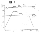
- the glass was preheated to 200°C at a place not shown, fed into a mold with a room temperature, and heated to 480°C (10 8.5 poise) in the heating stage. Then, the glass was transferred to the press stage 26, and, with the press cylinder 21 lowered, pressed for 10 seconds.
- the press time is not particularly important where it does not affect cycle time.
- the press pressure was 500 kg/cm2. Although the press pressure raises no problem even when it is 500 kg/cm2 or more, a press pressure of 1000 kg/cm2 or more is not preferable because a highly precise mold shape will be changed.
- the glass was transferred to the first cooling stage 27.
- the glass was applied with press pressure for 22 seconds.
- the cooling rate at this time of 1.8°C/sec the glass was cooled to 440°C (1011 poise).
- the glass was transferred to the second cooling stage 28 kept at 400°C, and held for 50 seconds as pressed condition.
- the glass became 405°C (1013 poise) at the cooling rate of 0.7°C/sec.
- the glass was rapidly cooled and taken out as a lens. The optical performances of the lens were superior.
- a glass material to be molded was SF8.
- the raw glass material was fed into a mold with a room temperature, and transferred to the heating stage 25.
- the glass was heated to 540°C (109 poise) in the heating stage 25.
- a heating temperature corresponding to 1010 poise or less allows formation to be completed in a short time, a temperature corresponding to 1010 poise or more is not preferable because it makes deformation difficult.
- the glass was transferred to the press stage 26, and, with the press cylinder 21 lowered, pressed for 10 seconds.
- the press pressure was 100 kg/cm2. Then, after the press pressure had been released, the glass was transferred to the first cooling stage 27.
- the glass After having been transferred to the first cooling stage 27 which was constantly kept at 415°C, the glass was applied with press pressure for 70 seconds. The cooling rate at this time was 2.5°C/sec for 1011 poise or less and 1.5°C/sec for 1011 to 1013 poise. Thus, after the glass had been pressed to its transition point or less, the press cylinder 21 was raised. Thereafter, even when the lens cooled to the glass transition point or less is cooled rapidly, no shape accuracy is affected. However, since the residual distortion is as very large as 200 nm/cm due to cooling in a short time, without being transferred to the second cooling stage and the quenching stage, the glass was fed to an annealing furnace by means not shown to remove the residual distortion to 5 nm/cm or less.
- the first cooling stage was constantly kept at 415°C, so that the glass was not released from the mold, allowing a highly precise pressed lens to be molded.
- the cooling rate for 1011 poise or less became 2.8°C/sec. and that for 1011 to 1013 poise became 2.0°C/sec. Accordingly, the glass was released from the mold at a value near 1011 poise, causing no lens performance to be obtained.
- a glass material to be molded was SF6.
- the raw glass material was fed into a mold with a room temperature, and transferred to the heating stage 25.
- the glass was heated to 520°C (108 poise) in the heating stage. At this time, although the glass may be heated to 108 poise or more, the heating time becomes long which has no effect to improve lens performance, so that the heating viscosity up to 108 poise is sufficient with respect to cycle time.
- the glass was transferred to the press stage 25, and, with the press cylinder 21 lowered, pressed for 10 seconds.
- the press pressure was 10 kg/cm2. Then, after the press pressure had been released, the glass was transferred to the first cooling stage 27.
- the glass After having been transferred to the first cooling stage 27 which was constantly kept at 465°C, the glass was applied with press pressure for 30 seconds. At this time, at the cooling rate of 1.5°C/sec, the glass was cooled to 470°C (1010 poise). Then, the glass was transferred to the second cooling stage 28 kept at 430°C, and held for 80 seconds as pressed condition. At this time, the glass became 431°C (1013 poise), and the cooling rate was 0.5°C/sec.
- the molding method was also the same as for the Example 1.
- the lens is liable to develop an eccentricity, and where the value is less than 0.02X, it gives a poor transferring properties, so that it is preferable to use the raw glass material within that range.
Landscapes
- Engineering & Computer Science (AREA)
- Chemical & Material Sciences (AREA)
- Manufacturing & Machinery (AREA)
- Materials Engineering (AREA)
- Organic Chemistry (AREA)
- Moulds For Moulding Plastics Or The Like (AREA)
Applications Claiming Priority (4)
| Application Number | Priority Date | Filing Date | Title |
|---|---|---|---|
| JP207636/88 | 1988-08-22 | ||
| JP63207636A JPH0255235A (ja) | 1988-08-22 | 1988-08-22 | ガラスレンズの成形型及び成形方法 |
| JP63263229A JPH0624992B2 (ja) | 1988-10-19 | 1988-10-19 | プレスレンズの成形金型およびその成形方法 |
| JP263229/88 | 1988-10-19 |
Publications (2)
| Publication Number | Publication Date |
|---|---|
| EP0356068A1 true EP0356068A1 (de) | 1990-02-28 |
| EP0356068B1 EP0356068B1 (de) | 1994-03-16 |
Family
ID=26516371
Family Applications (1)
| Application Number | Title | Priority Date | Filing Date |
|---|---|---|---|
| EP89308102A Expired - Lifetime EP0356068B1 (de) | 1988-08-22 | 1989-08-09 | Pressform und Formgebungsverfahren zum Herstellen von optischen Teilen |
Country Status (3)
| Country | Link |
|---|---|
| US (1) | US5015280A (de) |
| EP (1) | EP0356068B1 (de) |
| DE (1) | DE68913860T2 (de) |
Cited By (7)
| Publication number | Priority date | Publication date | Assignee | Title |
|---|---|---|---|---|
| EP0482624A1 (de) * | 1990-10-26 | 1992-04-29 | Matsushita Electric Industrial Co., Ltd. | Maschine zum Formen eines optischen Elements und Verfahren zur Herstellung dieses optischen Elements mittels einer Maschine |
| US5201927A (en) * | 1990-10-26 | 1993-04-13 | Matsushita Electric Industrial Co., Ltd. | Method of producing the optical element |
| EP0733598A1 (de) * | 1995-03-22 | 1996-09-25 | Matsushita Electric Industrial Co., Ltd. | Verfahren und Vorrichtung zum Herstellen von optischen Körpern |
| EP0728707A3 (de) * | 1995-02-24 | 1996-11-27 | Matsushita Electric Industrial Co Ltd | Verfahren zur Herstellung eines optischen Elements |
| EP0850887A1 (de) * | 1996-12-26 | 1998-07-01 | Hoya Corporation | Verfahren zum Herstellen eines Glasproduktes durch Pressformen |
| EP0878291A1 (de) * | 1997-05-14 | 1998-11-18 | Eastman Kodak Company | Verfahren zur Herstellung von Werkzeugen zum Giessen von ophthalmischen Diffraktionslinsen |
| WO2006015706A1 (de) * | 2004-08-09 | 2006-02-16 | Docter Optics Gmbh | Verfahren und vorrichtung zur herstellung von präzisionslinsen |
Families Citing this family (28)
| Publication number | Priority date | Publication date | Assignee | Title |
|---|---|---|---|---|
| US5252056A (en) * | 1990-03-16 | 1993-10-12 | Ciba-Geigy Corporation | Contact lens casting mould |
| JPH0431328A (ja) * | 1990-05-25 | 1992-02-03 | Canon Inc | 光学素子成形用型構造及びプレス成形方法 |
| US5160361A (en) * | 1990-06-13 | 1992-11-03 | Matsushita Electric Industrial Co., Ltd. | Method of manufacturing optical element |
| JPH04124041A (ja) * | 1990-09-12 | 1992-04-24 | Toshiba Mach Co Ltd | 高精度ガラスレンズの成形方法 |
| US5160749A (en) * | 1990-10-30 | 1992-11-03 | Minnesota Mining And Manufacturing Company | Three piece mold assembly for making an ocular device |
| US5211969A (en) * | 1990-11-02 | 1993-05-18 | Canon Kabushiki Kaisha | Mold for press molding of optical element |
| US5368790A (en) * | 1992-08-19 | 1994-11-29 | Greshes; Martin | Method for making lenses |
| US5820895A (en) * | 1996-06-04 | 1998-10-13 | Johnson & Johnson Vision Products, Inc. | Conductive probe for heating contact lens mold assemblies during demolding |
| JPH10101347A (ja) * | 1996-09-24 | 1998-04-21 | Fuji Photo Optical Co Ltd | 光学部品の射出成形装置及び射出成形方法 |
| US6368522B1 (en) | 2000-01-03 | 2002-04-09 | Johnson & Johnson Vision Care, Inc. | Mold for forming a contact lens and method of preventing formation of small strands of contact lens material during contact lens manufacture |
| US6663801B2 (en) * | 2001-04-06 | 2003-12-16 | Johnson & Johnson Vision Care, Inc. | Silicon carbide IR-emitter heating device and method for demolding lenses |
| JP2004279879A (ja) * | 2003-03-18 | 2004-10-07 | Alps Electric Co Ltd | ホルダ付光学素子 |
| TWI299325B (en) * | 2003-04-18 | 2008-08-01 | Hon Hai Prec Ind Co Ltd | Mold and method for making the mold |
| TWI248420B (en) * | 2003-04-18 | 2006-02-01 | Hon Hai Prec Ind Co Ltd | Mold and method for molding optical glass products |
| TWI262176B (en) * | 2003-04-25 | 2006-09-21 | Hon Hai Prec Ind Co Ltd | Mold for molding optical glass products and method for making the mold |
| DE10360259A1 (de) * | 2003-12-20 | 2005-07-28 | Schott Ag | Verfahren und Vorrichtung zum Blankpressen von Glas, hierfür eingesetzte Presse und eingesetzter Formblock mit Oberform und Unterform |
| US7275397B2 (en) * | 2004-05-21 | 2007-10-02 | Corning Incorporated | Method of molding a silica article |
| TW200714559A (en) * | 2005-10-13 | 2007-04-16 | Asia Optical Co Inc | The forming apparatus for glass molding and the multi-layered sleeve thereof |
| CN1951843B (zh) * | 2005-10-21 | 2011-09-28 | 鸿富锦精密工业(深圳)有限公司 | 光学元件成型装置 |
| JP2007191328A (ja) * | 2006-01-17 | 2007-08-02 | Fujinon Corp | 光学素子成形装置 |
| JP5642458B2 (ja) | 2010-09-01 | 2014-12-17 | オリンパス株式会社 | 成形型セット、及び、光学素子の製造方法 |
| KR101735974B1 (ko) * | 2012-09-28 | 2017-05-15 | 도시바 기카이 가부시키가이샤 | 성형 장치 |
| BR112015014122A2 (pt) | 2012-12-14 | 2017-07-11 | 3M Innovative Properties Co | método de polimerização de materiais etilenicamente insaturados com o uso de radiação ionizante |
| CN104837949A (zh) | 2012-12-14 | 2015-08-12 | 3M创新有限公司 | 通过使用电离辐射聚合烯键式不饱和材料来制备封装的粘弹性组合物的方法 |
| KR20150000611A (ko) * | 2013-06-25 | 2015-01-05 | 삼성디스플레이 주식회사 | 입체 유리의 제조 장치 및 제조 방법 |
| TWI529059B (zh) * | 2013-11-29 | 2016-04-11 | Taiwan Green Point Entpr Co | Injection molding machine and the use of the tablet press detection system and detection methods |
| JP6964050B2 (ja) * | 2018-07-20 | 2021-11-10 | オリンパス株式会社 | 光学素子の製造方法 |
| CN115259635A (zh) * | 2022-07-01 | 2022-11-01 | 天津大学 | 一种玻璃透镜模压成形方法 |
Citations (4)
| Publication number | Priority date | Publication date | Assignee | Title |
|---|---|---|---|---|
| GB1429343A (en) * | 1973-03-05 | 1976-03-24 | Pilkington Brothers Ltd | Shaping of glass to a desired form |
| US4481023A (en) * | 1981-10-30 | 1984-11-06 | Corning Glass Works | Process to mold precision glass articles |
| US4629489A (en) * | 1984-07-09 | 1986-12-16 | Hoya Corporation | Method of manufacturing pressed lenses |
| US4738703A (en) * | 1983-11-29 | 1988-04-19 | Tetsuro Izumitani | Method of molding optical lenses |
Family Cites Families (7)
| Publication number | Priority date | Publication date | Assignee | Title |
|---|---|---|---|---|
| US2059767A (en) * | 1934-10-26 | 1936-11-03 | Bausch & Lomb | Manufacture of ophthalmic lenses |
| US3887350A (en) * | 1974-02-11 | 1975-06-03 | Owens Illinois Inc | Fluid cooling of glass molds |
| JPS56378A (en) * | 1979-06-15 | 1981-01-06 | Teijin Ltd | Production of suede like raised fabric |
| JPS6126528A (ja) * | 1984-07-14 | 1986-02-05 | Hoya Corp | プレスレンズを製造する装置 |
| JPS6153126A (ja) * | 1984-08-20 | 1986-03-17 | Hoya Corp | 高精度プレスレンズの成形方法 |
| JPS6345137A (ja) * | 1986-08-13 | 1988-02-26 | Olympus Optical Co Ltd | 光学レンズの製造装置 |
| JPS63170229A (ja) * | 1987-01-08 | 1988-07-14 | Toshiba Mach Co Ltd | ガラスレンズのプレス成形装置 |
-
1989
- 1989-08-09 DE DE68913860T patent/DE68913860T2/de not_active Expired - Fee Related
- 1989-08-09 EP EP89308102A patent/EP0356068B1/de not_active Expired - Lifetime
- 1989-08-22 US US07/396,621 patent/US5015280A/en not_active Expired - Lifetime
Patent Citations (4)
| Publication number | Priority date | Publication date | Assignee | Title |
|---|---|---|---|---|
| GB1429343A (en) * | 1973-03-05 | 1976-03-24 | Pilkington Brothers Ltd | Shaping of glass to a desired form |
| US4481023A (en) * | 1981-10-30 | 1984-11-06 | Corning Glass Works | Process to mold precision glass articles |
| US4738703A (en) * | 1983-11-29 | 1988-04-19 | Tetsuro Izumitani | Method of molding optical lenses |
| US4629489A (en) * | 1984-07-09 | 1986-12-16 | Hoya Corporation | Method of manufacturing pressed lenses |
Non-Patent Citations (1)
| Title |
|---|
| PATENT ABSTRACTS OF JAPAN, unexamined applications, C field, vol. 10, no. 214, July 25, 1986 THE PATENT OFFICE JAPANESE GOVERNMENT page 58 c 362 * |
Cited By (12)
| Publication number | Priority date | Publication date | Assignee | Title |
|---|---|---|---|---|
| EP0482624A1 (de) * | 1990-10-26 | 1992-04-29 | Matsushita Electric Industrial Co., Ltd. | Maschine zum Formen eines optischen Elements und Verfahren zur Herstellung dieses optischen Elements mittels einer Maschine |
| US5188652A (en) * | 1990-10-26 | 1993-02-23 | Matsushita Electric Industrial Co., Ltd. | Machine for molding optical element |
| US5201927A (en) * | 1990-10-26 | 1993-04-13 | Matsushita Electric Industrial Co., Ltd. | Method of producing the optical element |
| EP0728707A3 (de) * | 1995-02-24 | 1996-11-27 | Matsushita Electric Industrial Co Ltd | Verfahren zur Herstellung eines optischen Elements |
| US5759457A (en) * | 1995-02-24 | 1998-06-02 | Matsushita Electric Industrial Co., Ltd. | Method for manufacturing an optical element |
| EP0733598A1 (de) * | 1995-03-22 | 1996-09-25 | Matsushita Electric Industrial Co., Ltd. | Verfahren und Vorrichtung zum Herstellen von optischen Körpern |
| US5766294A (en) * | 1995-03-22 | 1998-06-16 | Matsushita Electric Industrial Co, Ltd. | Method and apparatus for producing an optical element using a molding block and a temperature effecting mechanism contacting the molding block for heat exchange |
| EP0850887A1 (de) * | 1996-12-26 | 1998-07-01 | Hoya Corporation | Verfahren zum Herstellen eines Glasproduktes durch Pressformen |
| US6050110A (en) * | 1996-12-26 | 2000-04-18 | Hoya Corporation | Method for manufacturing glass product |
| US6434976B1 (en) | 1996-12-26 | 2002-08-20 | Hoya Corporation | Method for manufacturing glass product |
| EP0878291A1 (de) * | 1997-05-14 | 1998-11-18 | Eastman Kodak Company | Verfahren zur Herstellung von Werkzeugen zum Giessen von ophthalmischen Diffraktionslinsen |
| WO2006015706A1 (de) * | 2004-08-09 | 2006-02-16 | Docter Optics Gmbh | Verfahren und vorrichtung zur herstellung von präzisionslinsen |
Also Published As
| Publication number | Publication date |
|---|---|
| DE68913860D1 (de) | 1994-04-21 |
| US5015280A (en) | 1991-05-14 |
| EP0356068B1 (de) | 1994-03-16 |
| DE68913860T2 (de) | 1994-08-04 |
Similar Documents
| Publication | Publication Date | Title |
|---|---|---|
| EP0356068A1 (de) | Pressform und Formgebungsverfahren zum Herstellen von optischen Teilen | |
| US4738703A (en) | Method of molding optical lenses | |
| JPH0432008B2 (de) | ||
| US4883528A (en) | Apparatus for molding glass optical elements | |
| US4929265A (en) | Method of molding glass optical elements | |
| US4964903A (en) | Apparatus for molding glass molds | |
| EP1008562A2 (de) | Verfahren und Vorrichtung zum Pressformen eines Glassprodukts | |
| US5250099A (en) | Glass molding process and molding apparatus for the same | |
| JPH01160835A (ja) | 両凸レンズ素子の製造方法 | |
| JP2001180946A (ja) | 光学ガラス素子の成形方法およびその方法を用いた光学ガラス素子の成形装置 | |
| JPH0431328A (ja) | 光学素子成形用型構造及びプレス成形方法 | |
| US4897101A (en) | Method of forming a precision glass mold and article | |
| JPH07330347A (ja) | 光学素子成形方法 | |
| JPH0624992B2 (ja) | プレスレンズの成形金型およびその成形方法 | |
| EP0386944B1 (de) | Formvorrichtung und Verfahren | |
| JP2001270724A (ja) | 光学レンズ及びその成形金型 | |
| US5904747A (en) | Method of molding optical articles | |
| JP2000247653A (ja) | 光学素子成形用金型及び光学素子 | |
| JPH11255529A (ja) | 光学素子の成形装置 | |
| US6514444B1 (en) | Method of manufacturing a molded plastic article and a glass molding plastics | |
| JPS6346010B2 (de) | ||
| JP4373278B2 (ja) | 光学素子の成形方法 | |
| JP2001348232A (ja) | ガラス成形品、光学素子、複数の光学素子を同時に成形する成形方法、及び、成形用金型駒部材の位置出し方法、並びに、ガラスレンズの成形装置 | |
| KR0125997Y1 (ko) | 렌즈성형용 금형 | |
| JPH03295825A (ja) | 光学素子成形型および成形方法 |
Legal Events
| Date | Code | Title | Description |
|---|---|---|---|
| PUAI | Public reference made under article 153(3) epc to a published international application that has entered the european phase |
Free format text: ORIGINAL CODE: 0009012 |
|
| AK | Designated contracting states |
Kind code of ref document: A1 Designated state(s): DE FR GB NL |
|
| 17P | Request for examination filed |
Effective date: 19900803 |
|
| 17Q | First examination report despatched |
Effective date: 19911104 |
|
| GRAA | (expected) grant |
Free format text: ORIGINAL CODE: 0009210 |
|
| AK | Designated contracting states |
Kind code of ref document: B1 Designated state(s): DE FR GB NL |
|
| REF | Corresponds to: |
Ref document number: 68913860 Country of ref document: DE Date of ref document: 19940421 |
|
| ET | Fr: translation filed | ||
| PLBE | No opposition filed within time limit |
Free format text: ORIGINAL CODE: 0009261 |
|
| STAA | Information on the status of an ep patent application or granted ep patent |
Free format text: STATUS: NO OPPOSITION FILED WITHIN TIME LIMIT |
|
| 26N | No opposition filed | ||
| REG | Reference to a national code |
Ref country code: GB Ref legal event code: IF02 |
|
| REG | Reference to a national code |
Ref country code: GB Ref legal event code: 746 Effective date: 20031002 |
|
| REG | Reference to a national code |
Ref country code: FR Ref legal event code: D6 |
|
| PGFP | Annual fee paid to national office [announced via postgrant information from national office to epo] |
Ref country code: DE Payment date: 20070802 Year of fee payment: 19 |
|
| PGFP | Annual fee paid to national office [announced via postgrant information from national office to epo] |
Ref country code: GB Payment date: 20070809 Year of fee payment: 19 |
|
| PGFP | Annual fee paid to national office [announced via postgrant information from national office to epo] |
Ref country code: NL Payment date: 20070815 Year of fee payment: 19 |
|
| PGFP | Annual fee paid to national office [announced via postgrant information from national office to epo] |
Ref country code: FR Payment date: 20070808 Year of fee payment: 19 |
|
| GBPC | Gb: european patent ceased through non-payment of renewal fee |
Effective date: 20080809 |
|
| NLV4 | Nl: lapsed or anulled due to non-payment of the annual fee |
Effective date: 20090301 |
|
| PG25 | Lapsed in a contracting state [announced via postgrant information from national office to epo] |
Ref country code: NL Free format text: LAPSE BECAUSE OF NON-PAYMENT OF DUE FEES Effective date: 20090301 |
|
| REG | Reference to a national code |
Ref country code: FR Ref legal event code: ST Effective date: 20090430 |
|
| PG25 | Lapsed in a contracting state [announced via postgrant information from national office to epo] |
Ref country code: FR Free format text: LAPSE BECAUSE OF NON-PAYMENT OF DUE FEES Effective date: 20080901 Ref country code: DE Free format text: LAPSE BECAUSE OF NON-PAYMENT OF DUE FEES Effective date: 20090303 |
|
| PG25 | Lapsed in a contracting state [announced via postgrant information from national office to epo] |
Ref country code: GB Free format text: LAPSE BECAUSE OF NON-PAYMENT OF DUE FEES Effective date: 20080809 |