EP0356775A2 - Ladegeneratorgerät - Google Patents
Ladegeneratorgerät Download PDFInfo
- Publication number
- EP0356775A2 EP0356775A2 EP89114731A EP89114731A EP0356775A2 EP 0356775 A2 EP0356775 A2 EP 0356775A2 EP 89114731 A EP89114731 A EP 89114731A EP 89114731 A EP89114731 A EP 89114731A EP 0356775 A2 EP0356775 A2 EP 0356775A2
- Authority
- EP
- European Patent Office
- Prior art keywords
- voltage
- generator
- output
- battery
- current
- Prior art date
- Legal status (The legal status is an assumption and is not a legal conclusion. Google has not performed a legal analysis and makes no representation as to the accuracy of the status listed.)
- Withdrawn
Links
Images



Classifications
-
- H—ELECTRICITY
- H02—GENERATION; CONVERSION OR DISTRIBUTION OF ELECTRIC POWER
- H02P—CONTROL OR REGULATION OF ELECTRIC MOTORS, ELECTRIC GENERATORS OR DYNAMO-ELECTRIC CONVERTERS; CONTROLLING TRANSFORMERS, REACTORS OR CHOKE COILS
- H02P21/00—Arrangements or methods for the control of electric machines by vector control, e.g. by control of field orientation
-
- H—ELECTRICITY
- H02—GENERATION; CONVERSION OR DISTRIBUTION OF ELECTRIC POWER
- H02J—ELECTRIC POWER NETWORKS; CIRCUIT ARRANGEMENTS OR SYSTEMS FOR SUPPLYING OR DISTRIBUTING ELECTRIC POWER; SYSTEMS FOR STORING ELECTRIC ENERGY
- H02J7/00—Circuit arrangements for charging or discharging batteries or for supplying loads from batteries
- H02J7/14—Circuit arrangements for charging or discharging batteries or for supplying loads from batteries for charging batteries from dynamo-electric generators driven at varying speed, e.g. on vehicle
- H02J7/16—Regulation of the charging current or voltage by variation of field
- H02J7/24—Regulation of the charging current or voltage by variation of field using discharge tubes or semiconductor devices
Definitions
- the present invention relates to a charging generator apparatus to be driven by, for instance, an engine mounted on an automobile.
- FIG 4 is a circuit diagram of a conventional charging generator apparatus, wherein a reference numeral 1 designates a generator to be actuated by an engine (not shown) which comprises armature windings 101 having a three-phase star connection and a field winding 102, a numeral 2 designates a three-phase full-wave rectifier for rectifying the a.c.
- a reference numeral 1 designates a generator to be actuated by an engine (not shown) which comprises armature windings 101 having a three-phase star connection and a field winding 102
- a numeral 2 designates a three-phase full-wave rectifier for rectifying the a.c.
- a numeral 3 designates a voltage regulator which detects the output voltage of the three-phase full-wave rectifier 2 and turns on or off a transistor 301 to thereby control a field current flowing in the field winding 102 so that the output voltage of the generator 1 is maintained to be a predetermined level
- a numeral 4 designates a battery to be charged by the output voltage of the three-phase full-wave rectifier 2.
- the generator 1 When the generator 1 is actuated by the engine (not shown), a three-phase a.c. voltage is induced in the armature windings 101 since a field current is passed from the battery 4 through the field winding 102 and the transistor 301.
- the three-phase a.c. current is rectified by the three-phase full-wave rectifier 2 and charges the battery 4.
- the voltage regulator 3 interrupts the field current by turning off the transistor 301, whereby the output voltage of the generator 1 is reduced.
- the voltage regulator 3 turns on the transistor 301 so that the field current is passed through the field winding 102, and the output voltage of the generator 1 is again increased.
- the generator 1 charges the battery 4 by a predetermined voltage.
- the conventional charging generator apparatus required a requisite number of turns of the armature windings in order to obtain a predetermined revolutional speed for initiating power generation.
- the maximum output current at a high speed revolution is converged to a current value determined by the armature reaction as is well known.
- a field current is increased by a method as disclosed, for instance, in Japanese Unexamined Patent Publication No. 285698/1987 in order to assure the ability of charging at a low speed and to obtain a high output current at a high speed revolution.
- the copper loss, which is known as I2R of the armature windings is increased in proportion to the square of the output current when the output current is increased, whereby a large temperature rise is caused resulting in the lack of reliability.
- a charging generator apparatus which comprises a generator having armature windings and a field winding, a voltage reducing circuit for reducing the output voltage of the generator, a battery to be charged by the output voltage of the voltage reducing circuit, a voltage regulator for regulating the output of the generator by controlling a field current supplied to the field winding and a control circuit for controlling a voltage reducing ratio in the voltage reducing circuit.
- a reference numeral 1 designates a generator having armature windings 101 and a field winding 102
- a numeral 2 designates a three-phase full-wave rectifier for rectifying the a.c.
- a numeral 31 designates a voltage regulator which detects the output voltage of the generator 1 and controls a current flowing in the field winding 102 by turning on and off a transistor 311 to thereby control the output voltage of the generator 1 to a predetermined value V1
- a numeral 5 designates a voltagle reducing circuit for reducing the output voltage of the generator 1, wherein the collector of an NPN transistor 501 is connected to an output terminal of the three-phase full-wave rectifier 2; the emitter is connected to the positive terminal of a battery 4 through a reactor 502; and the negative terminal of the battery 4 is connected to the emitter of the transistor 501 through the diode 503.
- the second predetermined value V2 can be determined or changed depending on the condition of a load in operation, and the battery 4 is charged in such a manner that the second predetermined value V2 is smaller than the first predetermined value V1 of the output voltage of the generator 1.
- a value of voltage drop in the voltage reducing circuit is determined by the operating voltage of the control circuit.
- the transistor 311 When the output voltage of the generator 1 is lower than the second predetermined value V2, the transistor 311 is turned on because the detected voltage of the voltage regulator 31 is lower than the first predetermined value V1 and the field current flows at the maximum level. As the terminal voltage of the battery 4 is also lower than V2, the control circuit 6 renders the conductive rate of the transistor 501 to be the maximum. However, a charging current does not flow since the terminal voltage of the battery 4 is higher than the output voltage of the generator 1. On the other hand, in the conventional apparatus, since the detected voltage of the voltage regulator 3 is lower thant the predetermined value, the transistor 301 is turned on and the field current flows at the maximum level. However, a charging current does not flow because the terminal voltage of the battery 4 is higher than the output voltage of the generator 1.
- the transistor 311 When the output voltage of the generator 1 is higher than the second predetermined value V2 and lower than the first predetermined value 1, the transistor 311 is turned on because the detected voltage of the voltage regulator 31 is lower than V1 and the field current flows at the maximum level. Since the terminal voltage of the battery 4 tends to increase to the output voltage of the generator 1, the control circuit 6 which detects the output voltage of the generator 1 adjusts the conductive rate of the transistor 501 so that the terminal voltage of the battery 4 becomes V2. In this case, when the transistor 501 is in an ON state, a charging current is passed from the generator 1 through the three-phase full-wave rectifier 2, the transistor 501 and the reactor 502 to the battery 4 in order to charge it.
- the voltage regulator 31 When the output voltage of the generator 1 is higher than V1, the voltage regulator 31 turns on and off the transistor 311 so as to maintain the output voltage of the generator 1 to be V1, whereby the field current is controlled.
- the operations of the voltage reducing circuit 5 and the control circuit 6 are performed in the same manner as above so as to control the charging voltage to be V2.
- the operation of the conventional apparatus is also performed in the same manner as above.
- the copper loss of this embodiment is (V2/V1)2 times as large as that of the conventional apparatus, and accordingly, the copper loss becomes smaller than the conventional apparatus.
- Figure 2 is a diagram showning external load characteristic curves wherein the ordinate represents voltage and the abcissa represents current.
- a curve P shows the voltage and the current produced by the generator 1 when the revolutional speed of the generator is constant and the field current is also constant (when the maximum field current is passed).
- the condition to obtain the maximum output current can be given at a point a .
- the output voltage of the generator 1 is expressed by V2 and the output current is expressed by I0.
- the value V1 can be taken as the output voltage of the generator 1, namely, the condition of a point b can be taken. Namely the conditions of the output voltage V1 and the output current Il of the generator 1 can be given.
- the battery 4 is used for a power source for passing the field current.
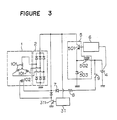
- the field current can be provided by the output voltage of the generator 1 as shown in Figure 3. Namely, it may be so constructed that when the key switch 9 is closed, a field current is passed from the battery 4 through a current limiting resistor 8, a diode 7, a field winding 102 and a transistor 311, whereby the generator 1 is actuated by an engine (not shown).
- the output voltage of the generator 1 is higher than the terminal voltage of the battery 4, a field current is passed through the field winding 102 and the transistor 311 by the output voltage of the generator 1.
- the number of turns of the field winding 102 can be increased in order to obtain the same strength of a magnetomotive force of the field winding; this requires only a small current. Accordingly, the wearing of brushes can be reduced and the capacity of current to the transistor 311 can be increased.
- the NPN type transistor is used as the transistor 501 in the voltage reducing circuit 5.
- a PNP type transistor or a field effect transistor (MOS FET) may be used.
- MOS FET field effect transistor
- a multiple-chopper may be used for the voltage reducing circuit 5.
- the voltage reducing circuit is connected to the generator to adjust a voltaging reducing ratio and a field current. Accordingly, it is possible to maintain the charging voltage to be constant and to increase an output current. Further, it is possible to control an armature current in the armature windings and to reduce the copper loss in the armature windings of the generator.
Landscapes
- Engineering & Computer Science (AREA)
- Power Engineering (AREA)
- Control Of Eletrric Generators (AREA)
- Control Of Charge By Means Of Generators (AREA)
Applications Claiming Priority (2)
| Application Number | Priority Date | Filing Date | Title |
|---|---|---|---|
| JP214329/88 | 1988-08-29 | ||
| JP63214329A JPH0265632A (ja) | 1988-08-29 | 1988-08-29 | 充電発電装置 |
Publications (2)
| Publication Number | Publication Date |
|---|---|
| EP0356775A2 true EP0356775A2 (de) | 1990-03-07 |
| EP0356775A3 EP0356775A3 (de) | 1991-01-23 |
Family
ID=16653949
Family Applications (1)
| Application Number | Title | Priority Date | Filing Date |
|---|---|---|---|
| EP19890114731 Withdrawn EP0356775A3 (de) | 1988-08-29 | 1989-08-09 | Ladegeneratorgerät |
Country Status (4)
| Country | Link |
|---|---|
| US (1) | US4940928A (de) |
| EP (1) | EP0356775A3 (de) |
| JP (1) | JPH0265632A (de) |
| KR (1) | KR920010003B1 (de) |
Cited By (2)
| Publication number | Priority date | Publication date | Assignee | Title |
|---|---|---|---|---|
| DE4216838A1 (de) * | 1992-05-21 | 1993-12-16 | Danijel Golub | Abtriebsfreie mechanische Bremse |
| EP1993198A4 (de) * | 2006-03-07 | 2017-08-02 | Mitsubishi Denki Kabushiki Kaisha | Ausgangsspannungssteuerung eines wechselstromgenerators für ein fahrzeug |
Families Citing this family (7)
| Publication number | Priority date | Publication date | Assignee | Title |
|---|---|---|---|---|
| JP2526667B2 (ja) * | 1989-06-05 | 1996-08-21 | 三菱電機株式会社 | 充電発電装置 |
| US5144220A (en) * | 1989-11-30 | 1992-09-01 | Mitsubishi Denki K.K. | Vehicle ac generator control system |
| US5231344A (en) * | 1990-01-17 | 1993-07-27 | Hitachi Ltd. | Control apparatus for electric generator |
| IT1240981B (it) * | 1990-10-22 | 1993-12-27 | Marelli Autronica | Circuito regolatore di tensione per un impianto di ricarica della batteria di un autoveicolo |
| US5402007A (en) * | 1993-11-04 | 1995-03-28 | General Motors Corporation | Method and apparatus for maintaining vehicle battery state-of-change |
| JP3415326B2 (ja) * | 1995-04-28 | 2003-06-09 | 株式会社デンソー | 車両用発電機の出力制御装置 |
| JP4270279B2 (ja) * | 2007-01-05 | 2009-05-27 | 株式会社デンソー | 車両用交流発電機の制御装置 |
Family Cites Families (11)
| Publication number | Priority date | Publication date | Assignee | Title |
|---|---|---|---|---|
| DE1588029A1 (de) * | 1967-01-26 | 1970-04-23 | Bosch Gmbh Robert | Einrichtung zum Erzeugen von Gleichstrom |
| JPS6026495Y2 (ja) * | 1977-11-02 | 1985-08-09 | 三菱電機株式会社 | 充電発電機制御装置 |
| DE3068863D1 (en) * | 1979-05-28 | 1984-09-13 | Nippon Denso Co | Generation control apparatus for vehicle generators |
| JPS6034336B2 (ja) * | 1979-09-27 | 1985-08-08 | 株式会社デンソー | 車両用電圧制御装置 |
| FR2533375B1 (fr) * | 1982-09-22 | 1986-06-20 | Renault | Dispositif generateur d'energie electrique pour vehicule, a alternateur polyphase et regulateur de tension |
| JPS59169337A (ja) * | 1983-03-17 | 1984-09-25 | 日産自動車株式会社 | 充電発電装置 |
| JPS6022500A (ja) * | 1983-07-15 | 1985-02-04 | Mitsubishi Electric Corp | 充電発電機の制御装置 |
| JPS6070936A (ja) * | 1983-09-22 | 1985-04-22 | 株式会社デンソー | 車両充電発電機用制御装置 |
| US4636706A (en) * | 1985-09-12 | 1987-01-13 | General Motors Corporation | Generator voltage regulating system |
| JPH079570Y2 (ja) * | 1987-02-26 | 1995-03-06 | 三菱電機株式会社 | 車両用交流発電機の制御装置 |
| JPH0612934B2 (ja) * | 1988-02-23 | 1994-02-16 | 日本電装株式会社 | 車両の充電制御装置 |
-
1988
- 1988-08-29 JP JP63214329A patent/JPH0265632A/ja active Pending
-
1989
- 1989-07-31 US US07/387,039 patent/US4940928A/en not_active Expired - Fee Related
- 1989-08-09 EP EP19890114731 patent/EP0356775A3/de not_active Withdrawn
- 1989-08-25 KR KR1019890012116A patent/KR920010003B1/ko not_active Expired
Cited By (2)
| Publication number | Priority date | Publication date | Assignee | Title |
|---|---|---|---|---|
| DE4216838A1 (de) * | 1992-05-21 | 1993-12-16 | Danijel Golub | Abtriebsfreie mechanische Bremse |
| EP1993198A4 (de) * | 2006-03-07 | 2017-08-02 | Mitsubishi Denki Kabushiki Kaisha | Ausgangsspannungssteuerung eines wechselstromgenerators für ein fahrzeug |
Also Published As
| Publication number | Publication date |
|---|---|
| KR920010003B1 (ko) | 1992-11-10 |
| KR900004092A (ko) | 1990-03-27 |
| EP0356775A3 (de) | 1991-01-23 |
| JPH0265632A (ja) | 1990-03-06 |
| US4940928A (en) | 1990-07-10 |
Similar Documents
| Publication | Publication Date | Title |
|---|---|---|
| US5059886A (en) | Charging generator | |
| US5355071A (en) | Power source apparatus for vehicles | |
| US5418401A (en) | Power supply apparatus for a vehicle having batteries of different voltages which are charged according to alternator speed | |
| US5323102A (en) | Power source unit for an automotive vehicle | |
| JP3039119B2 (ja) | 車両用電源装置 | |
| US5672954A (en) | Control system for AC generator | |
| US5497071A (en) | Output power control device for automotive AC generator | |
| US6344734B1 (en) | Controller of AC generator for use in vehicles | |
| JPS62104500A (ja) | 車両用発電機の制御装置 | |
| EP0524466A2 (de) | Steuereinrichtung für einen Wechselstromgenerator eines Fahrzeuges | |
| US4940928A (en) | Charging generator apparatus | |
| EP0178395B1 (de) | Generatorspannungsregler | |
| US3510746A (en) | Transistor controlled battery charger | |
| US3568041A (en) | Alternator control device having simplified charge-discharge indicator | |
| JP2837687B2 (ja) | 充電装置 | |
| US4525662A (en) | Battery charging control system for automobile | |
| US4451776A (en) | Charging generator control system | |
| US4197492A (en) | Current generating system with output winding switching device | |
| US5563497A (en) | Control device for AC generator | |
| US4024456A (en) | Generator system with speed responsive output winding switching device | |
| US4642548A (en) | Control apparatus for charging generator | |
| JPH0670482A (ja) | 発電装置 | |
| CN113725985B (zh) | 用于充电电路的变速风机供电模块及供电方法 | |
| US4465965A (en) | Power limiting apparatus | |
| GB2143094A (en) | Circuit for charging a secondary cell |
Legal Events
| Date | Code | Title | Description |
|---|---|---|---|
| PUAI | Public reference made under article 153(3) epc to a published international application that has entered the european phase |
Free format text: ORIGINAL CODE: 0009012 |
|
| AK | Designated contracting states |
Kind code of ref document: A2 Designated state(s): FR GB IT |
|
| PUAL | Search report despatched |
Free format text: ORIGINAL CODE: 0009013 |
|
| AK | Designated contracting states |
Kind code of ref document: A3 Designated state(s): FR GB IT |
|
| 17P | Request for examination filed |
Effective date: 19901212 |
|
| 17Q | First examination report despatched |
Effective date: 19921015 |
|
| 18W | Application withdrawn |
Withdrawal date: 19940112 |
|
| STAA | Information on the status of an ep patent application or granted ep patent |
Free format text: STATUS: THE APPLICATION HAS BEEN WITHDRAWN |
|
| R18W | Application withdrawn (corrected) |
Effective date: 19940112 |
|
| APAF | Appeal reference modified |
Free format text: ORIGINAL CODE: EPIDOSCREFNE |