EP0356840A2 - Lampe à décharge à haute pression - Google Patents
Lampe à décharge à haute pression Download PDFInfo
- Publication number
- EP0356840A2 EP0356840A2 EP89115287A EP89115287A EP0356840A2 EP 0356840 A2 EP0356840 A2 EP 0356840A2 EP 89115287 A EP89115287 A EP 89115287A EP 89115287 A EP89115287 A EP 89115287A EP 0356840 A2 EP0356840 A2 EP 0356840A2
- Authority
- EP
- European Patent Office
- Prior art keywords
- plug
- electrode
- pockets
- stopper
- lamp according
- Prior art date
- Legal status (The legal status is an assumption and is not a legal conclusion. Google has not performed a legal analysis and makes no representation as to the accuracy of the status listed.)
- Granted
Links
Images



Classifications
-
- H—ELECTRICITY
- H01—ELECTRIC ELEMENTS
- H01J—ELECTRIC DISCHARGE TUBES OR DISCHARGE LAMPS
- H01J61/00—Gas-discharge or vapour-discharge lamps
- H01J61/02—Details
- H01J61/30—Vessels; Containers
-
- H—ELECTRICITY
- H01—ELECTRIC ELEMENTS
- H01J—ELECTRIC DISCHARGE TUBES OR DISCHARGE LAMPS
- H01J61/00—Gas-discharge or vapour-discharge lamps
- H01J61/02—Details
- H01J61/36—Seals between parts of vessels; Seals for leading-in conductors; Leading-in conductors
Definitions
- High-pressure sodium discharge lamps are operated almost without exception as saturated discharge lamps: during operation, only a part of the metal filling, normally mercury and sodium, is evaporated, while the rest is condensed as liquid amalgam at one or more points, the so-called "cold spots".
- the unsaturated discharge lamp high-pressure mercury lamp
- the operating voltage determines the lamp power during normal choke operation and thus brings about a positive feedback to the coldspot temperature.
- the tube In the usual discharge vessel designs for "inner amalgam", the tube is closed by a sintered or soldered with glass solder cylindrical ceramic stopper with a smooth inner end face.
- the conductive connection to the electrode is made centrally in the plug by means of a niobium tube or niobium wire bushing (DE-OS 28 14 411).
- a niobium tube or niobium wire bushing DE-OS 28 14 411.
- the simplest way to influence the coldspot temperature is to change the distance between the core pin tip and the plug.
- the possibilities of increasing the temperature by shortening this distance are subject to geometric limits if the rear end of the electrode coil abuts the end of the niobium current lead-through element.
- Higher coldspot temperatures with unchanged ceramic tube construction can then only be achieved by external Heat accumulation measures, in particular heat accumulation collars, as are described, for example, in US Pat. No. 3,723,784. Since the assembly of such heat accumulation sleeves is complex, there is considerable interest in a plug construction in which the cold spot temperature is increased compared to the conventional plug construction.
- the object of the present invention is to provide an improved configuration of the stopper area in high-pressure sodium discharge lamps, in which the amalgam depot is designed as an “internal amalgam”.
- the vibration-insensitive accommodation of a sufficiently large amount of amalgam should be taken into account in the simplest possible way and at a location that is protected from the sheet set and at which the interruption of the line of sight between the electrode and the analgam depot becomes fully effective.
- Another object of the invention is to increase the coldspot temperature compared to the temperature which can be achieved in the discharge vessel designs according to the prior art for "internal amalgam", with additional external heat accumulation measures to be dispensed with in view of the applications mentioned above.
- the webs result in a much better coaxial alignment of the stopper, since the full stopper length is used for the alignment, and not only the comparatively short stopper piece behind the groove. This significantly reduces the risk of a one-sided shortfall in the critical groove thickness due to the non-coaxial plug position.
- a pocket plug offers advantages over a plug with an annular groove.
- the tasks described above can be safely performed.
- the depth of the pockets should advantageously be chosen sufficiently large to accommodate the 20 to 30 mg of amalgam required as a buffer supply.
- the plug height With a suitable choice of the plug height, it is also possible to set the desired increase in the cold spot temperature. But it turns out that there are limits to this approach. Above a critical filling level of the pockets, a new cold spot is created behind the electrodes and the amalgam begins to condense in the plug bore near the niobium bushing. This would violate an essential requirement, namely the safe electrical isolation between the electrode and the amalgam. In fact, such lamps again show the undesirable ignition behavior with an arc at the amalgam. As a countermeasure, the pocket plugs, which are designed for increased cold spot temperature, are therefore designed with a conically widened bore. The conical widening results in improved heat radiation from the discharge at the lead-through end of the plug bore.
- the size of this temperature increase determines the overall possible increase in the cold spot temperature. In order to achieve the greatest possible effect, the largest possible opening angle should be selected. This results from the minimum wall thickness between the pocket and the maximum cone opening (d3 - d2): 2 - D.
- FIG. 1 shows a high-pressure sodium discharge lamp 1 of 150 W.
- the discharge vessel 4 made of polycrystalline aluminum oxide ceramic is held inside the outer bulb 2, to which a base 3 is attached for connecting a supply voltage.
- two getter rings 5 are mounted inside the outer bulb 2.
- FIG. 2 The construction of the melting of the discharge vessel 4 is shown in detail in FIG. 2.
- a tubular body 6 made of aluminum oxide Ceramic is a plug 7, which is also made of aluminum oxide ceramic and is sintered in gastight.
- the stopper 7 has an axially running bore into which a current supply 8 made of niobium is melted in a gas-tight manner by means of a commercially available glass solder (not shown).
- the electrode consisting of electrode pin 10 and the electrode coil 11, is fastened in the power supply 8 by means of titanium soldering 9.
- the other end of the discharge vessel 4, not shown here is constructed essentially in the same way.
- the plug 7 consists of a cylindrical part 12 and a conical part 13 of approximately the same length.
- the length L of the plug 7 is designed such that its conical part 13 facing the discharge space extends beyond the part of the electrode coil 11 facing away from the discharge, whereby the conically widening bore faces the electrode pin 10 and the electrode coil 11.
- the opening angle ⁇ of the conical part 13 is as large as possible.
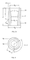
- the stopper 7 is provided according to the invention with three annular segment-shaped pockets 14 which are evenly distributed on its circumference.
- the pockets 14 are delimited by webs 15, the pockets 14 and the webs 15 each having the same size, ie the segment angle ⁇ of a pocket 14 and a web 15 is 120 ° taken together.
- the tubular body 6 has a length of approximately 86 mm, an outer diameter of approximately 7.4 mm and an inner diameter of approximately 6 mm.
- the stopper 7 with its total length L of approximately 9 mm is provided with an axially extending bore with a diameter d 1 of approximately 3.1 mm.
- the conical part 13 has a largest inner diameter d2 of about 5 mm, which corresponds to an opening angle ⁇ of 24 °.
- the outer diameter d3 of the plug 7 is equal to the inner diameter of the tubular body 6.
- the depth T of the pockets is approximately 5.5 mm, the transition from the inner flank of the pocket 14 to the outer diameter d3 of the closure part 7 expediently at an angle ⁇ of 45 ° is executed.
- the thickness D of the pockets 14 is dependent on the outer diameter d3 of the plug 7 and the largest diameter d2 of the conical part 12. In the present embodiment of a 150 W lamp, the thickness D of the pocket 14 is approximately 0.4 mm.
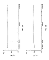
- Figures 5a to 5d show different parameters of a 150 W sodium high pressure discharge lamp during its burning time.
- the electrical power P L (FIG. 5a) of the lamp 1 moves during its 9000 burning hours in a very narrow range of only about 5 W deviation from the nominal power.
- the operating voltage U L (FIG. 5b) shows only a slight increase of approx. 5 V during this time, starting from approx. 100 V for a lamp burned in for approx. 100 hours.
- At the luminous flux ⁇ (Fig. 5c) there are no changes during the entire burning time of 9000 h tion measurable; it is constantly around 15,000 lm.
- the luminous efficacy ⁇ (FIG. 5d) of approx. 100 lm / W can also be classified as extremely low with a decrease of approx. 4% over the entire burning time of the lamp.
Landscapes
- Vessels And Coating Films For Discharge Lamps (AREA)
- Discharge Lamps And Accessories Thereof (AREA)
Applications Claiming Priority (2)
| Application Number | Priority Date | Filing Date | Title |
|---|---|---|---|
| DE3829729A DE3829729A1 (de) | 1988-09-01 | 1988-09-01 | Hochdruckentladungslampe |
| DE3829729 | 1988-09-01 |
Publications (3)
| Publication Number | Publication Date |
|---|---|
| EP0356840A2 true EP0356840A2 (fr) | 1990-03-07 |
| EP0356840A3 EP0356840A3 (fr) | 1991-05-02 |
| EP0356840B1 EP0356840B1 (fr) | 1994-03-09 |
Family
ID=6362094
Family Applications (1)
| Application Number | Title | Priority Date | Filing Date |
|---|---|---|---|
| EP89115287A Expired - Lifetime EP0356840B1 (fr) | 1988-09-01 | 1989-08-18 | Lampe à décharge à haute pression |
Country Status (5)
| Country | Link |
|---|---|
| US (1) | US5015913A (fr) |
| EP (1) | EP0356840B1 (fr) |
| JP (1) | JPH02106866A (fr) |
| KR (1) | KR900005548A (fr) |
| DE (2) | DE3829729A1 (fr) |
Cited By (2)
| Publication number | Priority date | Publication date | Assignee | Title |
|---|---|---|---|---|
| EP0720208A3 (fr) * | 1994-12-28 | 1997-01-15 | Matsushita Electronics Corp | Lampe fluorescente circulaire |
| EP1182681A1 (fr) * | 2000-08-23 | 2002-02-27 | General Electric Company | Tube à arc pour lampe à halogénure métallique fait de céramique moulée par injection et présentant une extrémité non oblique; procédé de fabrication de ce tube |
Families Citing this family (8)
| Publication number | Priority date | Publication date | Assignee | Title |
|---|---|---|---|---|
| EP0561450B1 (fr) * | 1992-03-16 | 1996-06-12 | Koninklijke Philips Electronics N.V. | Lampe à sodium à haute pression |
| US5434472A (en) * | 1992-04-15 | 1995-07-18 | United States Philips Corporation | High-pressure sodium discharge lamp with getter |
| US5290638A (en) * | 1992-07-24 | 1994-03-01 | Massachusetts Institute Of Technology | Superconducting joint with niobium-tin |
| US6583563B1 (en) * | 1998-04-28 | 2003-06-24 | General Electric Company | Ceramic discharge chamber for a discharge lamp |
| US7297037B2 (en) * | 1998-04-28 | 2007-11-20 | General Electric Company | Ceramic discharge chamber for a discharge lamp |
| DE20307607U1 (de) * | 2003-05-15 | 2004-09-23 | Zumtobel Staff Gmbh | Beleuchtungsanordnung bestehend aus einer Gasentladungslampe und einer Abschirmhülse |
| US7282864B2 (en) * | 2004-09-09 | 2007-10-16 | Seiko Epson Corporation | Discharge lamp and control of the same |
| US8319431B2 (en) * | 2010-06-25 | 2012-11-27 | General Electric Company | Ceramic arc tube for a discharge lamp and method of making same |
Family Cites Families (6)
| Publication number | Priority date | Publication date | Assignee | Title |
|---|---|---|---|---|
| US3450924A (en) * | 1967-05-23 | 1969-06-17 | Westinghouse Electric Corp | Sealing means for refractory ceramic discharge device envelopes |
| US3723784A (en) * | 1971-04-15 | 1973-03-27 | Gen Electric | Alumina ceramic lamp having heat-reflecting shields surrounding its electrodes |
| DE2209848A1 (de) * | 1972-03-01 | 1973-09-06 | Patra Patent Treuhand | Vakuumdichter verschluss bei metalldampfhochdruckentladungslampen |
| NL172194C (nl) * | 1973-02-16 | 1983-07-18 | Philips Nv | Hogedrukontladingslamp. |
| NL181764C (nl) * | 1977-04-15 | 1987-10-16 | Philips Nv | Hogedrukmetaaldampontladingslamp. |
| GB2105904B (en) * | 1981-09-04 | 1985-10-23 | Emi Plc Thorn | High pressure discharge lamps |
-
1988
- 1988-09-01 DE DE3829729A patent/DE3829729A1/de not_active Withdrawn
-
1989
- 1989-08-17 US US07/395,354 patent/US5015913A/en not_active Expired - Fee Related
- 1989-08-18 DE DE89115287T patent/DE58907168D1/de not_active Expired - Fee Related
- 1989-08-18 EP EP89115287A patent/EP0356840B1/fr not_active Expired - Lifetime
- 1989-09-01 JP JP1224756A patent/JPH02106866A/ja active Pending
- 1989-09-01 KR KR1019890012639A patent/KR900005548A/ko not_active Ceased
Cited By (2)
| Publication number | Priority date | Publication date | Assignee | Title |
|---|---|---|---|---|
| EP0720208A3 (fr) * | 1994-12-28 | 1997-01-15 | Matsushita Electronics Corp | Lampe fluorescente circulaire |
| EP1182681A1 (fr) * | 2000-08-23 | 2002-02-27 | General Electric Company | Tube à arc pour lampe à halogénure métallique fait de céramique moulée par injection et présentant une extrémité non oblique; procédé de fabrication de ce tube |
Also Published As
| Publication number | Publication date |
|---|---|
| DE58907168D1 (de) | 1994-04-14 |
| KR900005548A (ko) | 1990-04-14 |
| EP0356840A3 (fr) | 1991-05-02 |
| DE3829729A1 (de) | 1990-03-15 |
| EP0356840B1 (fr) | 1994-03-09 |
| US5015913A (en) | 1991-05-14 |
| JPH02106866A (ja) | 1990-04-18 |
Similar Documents
| Publication | Publication Date | Title |
|---|---|---|
| DE69812069T2 (de) | Metallhalogenidlampe | |
| DE3133642C2 (fr) | ||
| DE69600960T2 (de) | Hochdruckentladungslampe | |
| EP0536609A1 (fr) | Lampe à décharge à haute pression | |
| WO1988009565A1 (fr) | Lampe a decharge xenon a arc court | |
| EP0356840B1 (fr) | Lampe à décharge à haute pression | |
| EP0335202B1 (fr) | Lampe à décharge à haute pression, en particulier lampe à vapeur de sodium à haute pression | |
| DE3207663A1 (de) | Ueberspannungsableiter mit einem gasgefuellten gehaeuse | |
| DE69501615T2 (de) | Quecksilberlampe vom Kurzbogentyp | |
| DE69507696T2 (de) | Niederdruckquecksilberdampfentladungslampe | |
| EP0321866A2 (fr) | Lampe à d'echarge à haute pression | |
| EP0639853B1 (fr) | Lampe à décharge à haute pression avec récipient à décharge en céramique | |
| DE2032899C2 (de) | Schutzfunkenstrecke | |
| DE69608261T2 (de) | Niederdruckentladungslampe | |
| DE3044121C2 (de) | Natriumhochdrucklampe | |
| DE3200699A1 (de) | Entladungsgefaess fuer hochdruck-natriumdampflampen | |
| EP1372184A2 (fr) | Système d'électrodes pour une lampe aux halogénures métalliques et lampe équipée d'un tel système | |
| DE19911727A1 (de) | Natriumhochdrucklampe mit Zündhilfe | |
| WO2008074361A1 (fr) | Électrode pour une lampe à décharge | |
| CH171154A (de) | Entladungsröhre mit Gasfüllung und Glühkathode zum Gleichrichten von Wechselstrom. | |
| DE1949946B2 (de) | Hohlraumelektrode für eine Hochdruck-Metalldampflampe | |
| AT142427B (de) | Entladungsröhre mit Bogenentladung für hohe Spannungen. | |
| DE1033757B (de) | Vakuumschalter mit eingebauter Ionisationsgetterpumpe | |
| DE3111278C2 (fr) | ||
| DE102010031280A1 (de) | Hochdruckentladungslampe mit Zündhilfe |
Legal Events
| Date | Code | Title | Description |
|---|---|---|---|
| PUAI | Public reference made under article 153(3) epc to a published international application that has entered the european phase |
Free format text: ORIGINAL CODE: 0009012 |
|
| AK | Designated contracting states |
Kind code of ref document: A2 Designated state(s): BE DE FR GB IT |
|
| 17P | Request for examination filed |
Effective date: 19901220 |
|
| PUAL | Search report despatched |
Free format text: ORIGINAL CODE: 0009013 |
|
| AK | Designated contracting states |
Kind code of ref document: A3 Designated state(s): BE DE FR GB IT |
|
| 17Q | First examination report despatched |
Effective date: 19930624 |
|
| GRAA | (expected) grant |
Free format text: ORIGINAL CODE: 0009210 |
|
| AK | Designated contracting states |
Kind code of ref document: B1 Designated state(s): BE DE FR GB IT |
|
| REF | Corresponds to: |
Ref document number: 58907168 Country of ref document: DE Date of ref document: 19940414 |
|
| ITF | It: translation for a ep patent filed | ||
| GBT | Gb: translation of ep patent filed (gb section 77(6)(a)/1977) |
Effective date: 19940516 |
|
| ET | Fr: translation filed | ||
| PGFP | Annual fee paid to national office [announced via postgrant information from national office to epo] |
Ref country code: GB Payment date: 19940718 Year of fee payment: 6 |
|
| PGFP | Annual fee paid to national office [announced via postgrant information from national office to epo] |
Ref country code: BE Payment date: 19940818 Year of fee payment: 6 |
|
| PGFP | Annual fee paid to national office [announced via postgrant information from national office to epo] |
Ref country code: FR Payment date: 19940824 Year of fee payment: 6 |
|
| PGFP | Annual fee paid to national office [announced via postgrant information from national office to epo] |
Ref country code: DE Payment date: 19941018 Year of fee payment: 6 |
|
| PLBE | No opposition filed within time limit |
Free format text: ORIGINAL CODE: 0009261 |
|
| STAA | Information on the status of an ep patent application or granted ep patent |
Free format text: STATUS: NO OPPOSITION FILED WITHIN TIME LIMIT |
|
| 26N | No opposition filed | ||
| PG25 | Lapsed in a contracting state [announced via postgrant information from national office to epo] |
Ref country code: GB Effective date: 19950818 |
|
| PG25 | Lapsed in a contracting state [announced via postgrant information from national office to epo] |
Ref country code: BE Effective date: 19950831 |
|
| BERE | Be: lapsed |
Owner name: PATENT-TREUHAND-G.- FUR ELEKTRISCHE GLUHLAMPEN M. Effective date: 19950831 |
|
| GBPC | Gb: european patent ceased through non-payment of renewal fee |
Effective date: 19950818 |
|
| PG25 | Lapsed in a contracting state [announced via postgrant information from national office to epo] |
Ref country code: FR Effective date: 19960430 |
|
| PG25 | Lapsed in a contracting state [announced via postgrant information from national office to epo] |
Ref country code: DE Effective date: 19960501 |
|
| REG | Reference to a national code |
Ref country code: FR Ref legal event code: ST |
|
| PG25 | Lapsed in a contracting state [announced via postgrant information from national office to epo] |
Ref country code: IT Free format text: LAPSE BECAUSE OF NON-PAYMENT OF DUE FEES;WARNING: LAPSES OF ITALIAN PATENTS WITH EFFECTIVE DATE BEFORE 2007 MAY HAVE OCCURRED AT ANY TIME BEFORE 2007. THE CORRECT EFFECTIVE DATE MAY BE DIFFERENT FROM THE ONE RECORDED. Effective date: 20050818 |