EP0357356B1 - Couvercle rompable pour compartiment de sac à air de véhicule - Google Patents
Couvercle rompable pour compartiment de sac à air de véhicule Download PDFInfo
- Publication number
- EP0357356B1 EP0357356B1 EP89308667A EP89308667A EP0357356B1 EP 0357356 B1 EP0357356 B1 EP 0357356B1 EP 89308667 A EP89308667 A EP 89308667A EP 89308667 A EP89308667 A EP 89308667A EP 0357356 B1 EP0357356 B1 EP 0357356B1
- Authority
- EP
- European Patent Office
- Prior art keywords
- rupturable
- cover
- air bag
- sections
- membrane
- Prior art date
- Legal status (The legal status is an assumption and is not a legal conclusion. Google has not performed a legal analysis and makes no representation as to the accuracy of the status listed.)
- Expired - Lifetime
Links
- 239000012528 membrane Substances 0.000 claims description 16
- 239000000463 material Substances 0.000 claims description 6
- 229920001169 thermoplastic Polymers 0.000 claims description 3
- 239000004416 thermosoftening plastic Substances 0.000 claims description 3
- 229920001971 elastomer Polymers 0.000 claims description 2
- 239000000806 elastomer Substances 0.000 claims description 2
- 150000002148 esters Chemical class 0.000 claims description 2
- 239000011324 bead Substances 0.000 description 4
- 238000004519 manufacturing process Methods 0.000 description 3
- PPBRXRYQALVLMV-UHFFFAOYSA-N Styrene Chemical compound C=CC1=CC=CC=C1 PPBRXRYQALVLMV-UHFFFAOYSA-N 0.000 description 2
- -1 polybutylene terephthalate Polymers 0.000 description 2
- NLHHRLWOUZZQLW-UHFFFAOYSA-N Acrylonitrile Chemical compound C=CC#N NLHHRLWOUZZQLW-UHFFFAOYSA-N 0.000 description 1
- 239000004952 Polyamide Substances 0.000 description 1
- 239000004793 Polystyrene Substances 0.000 description 1
- 230000006978 adaptation Effects 0.000 description 1
- 239000000956 alloy Substances 0.000 description 1
- 229910045601 alloy Inorganic materials 0.000 description 1
- 238000010276 construction Methods 0.000 description 1
- 230000009977 dual effect Effects 0.000 description 1
- 229940014425 exodus Drugs 0.000 description 1
- 230000004048 modification Effects 0.000 description 1
- 238000012986 modification Methods 0.000 description 1
- 238000000465 moulding Methods 0.000 description 1
- 229920002647 polyamide Polymers 0.000 description 1
- 229920001707 polybutylene terephthalate Polymers 0.000 description 1
- 229920000515 polycarbonate Polymers 0.000 description 1
- 239000004417 polycarbonate Substances 0.000 description 1
- 229920000139 polyethylene terephthalate Polymers 0.000 description 1
- 239000005020 polyethylene terephthalate Substances 0.000 description 1
- 229920000642 polymer Polymers 0.000 description 1
- 229920000098 polyolefin Polymers 0.000 description 1
- 229920006324 polyoxymethylene Polymers 0.000 description 1
- 229920002223 polystyrene Polymers 0.000 description 1
- 229920002635 polyurethane Polymers 0.000 description 1
- 239000004814 polyurethane Substances 0.000 description 1
- 238000000926 separation method Methods 0.000 description 1
- 125000000383 tetramethylene group Chemical group [H]C([H])([*:1])C([H])([H])C([H])([H])C([H])([H])[*:2] 0.000 description 1
- 229920002397 thermoplastic olefin Polymers 0.000 description 1
- 229920006346 thermoplastic polyester elastomer Polymers 0.000 description 1
Images
Classifications
-
- B—PERFORMING OPERATIONS; TRANSPORTING
- B60—VEHICLES IN GENERAL
- B60R—VEHICLES, VEHICLE FITTINGS, OR VEHICLE PARTS, NOT OTHERWISE PROVIDED FOR
- B60R21/00—Arrangements or fittings on vehicles for protecting or preventing injuries to occupants or pedestrians in case of accidents or other traffic risks
- B60R21/02—Occupant safety arrangements or fittings, e.g. crash pads
- B60R21/16—Inflatable occupant restraints or confinements designed to inflate upon impact or impending impact, e.g. air bags
- B60R21/20—Arrangements for storing inflatable members in their non-use or deflated condition; Arrangement or mounting of air bag modules or components
- B60R21/215—Arrangements for storing inflatable members in their non-use or deflated condition; Arrangement or mounting of air bag modules or components characterised by the covers for the inflatable member
- B60R21/2165—Arrangements for storing inflatable members in their non-use or deflated condition; Arrangement or mounting of air bag modules or components characterised by the covers for the inflatable member characterised by a tear line for defining a deployment opening
Definitions
- the present invention is directed to a rupturable cover for a vehicle air bag system.
- a device according to the preamble of claim 1 is disclosed in US-A-3 622 176.
- the principal object of the present invention is to provide a rupturable cover for a vehicle air bag system which is light-weight, operates effectively over a wide range of temperatures without fracturing or becoming inoperative, and is cost effective to manufacture.
- Another object of the present invention is to provide a one-piece rupturable cover for a vehicle air bag compartment which can be manufactured in a one step molding operation and is easy to install in a motor vehicle.
- the objects of this invention are achieved by providing a one-piece rupturable cover designed to open under a predetermined set of conditions.
- the design incorporates a rupturable membrane which functions as a tear seam and "S-shaped" flexible hinges which are integral with the cover.
- a rupturable membrane which functions as a tear seam
- S-shaped flexible hinges which are integral with the cover.
- the rupturable cover of this invention as illustrated in the following figures is adapted for attachment on the passenger side of a motor vehicle.
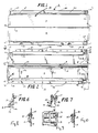
- the rupturable cover A includes two sections 2 and 4 which are connected to each other by an integrally molded rupturable seam or membrane 6.
- the cover A is generally rectangular in shape and is made from a thermoplastic polymeric material. Although sections 2 and 4 are connected about a horizontal line, it is well within the scope of this invention to include a rupturable cover for a vehicle air bag compartment in which sections 2 and 4 are connected about a vertical line.
- the tear pattern selected will depend on whether the cover is mounted on the passenger side of the vehicle or on the steering wheel. The pattern is not critical so long as, on opening, the bag is deployed uniformly.
- each section 2 and 4 includes a uniform groove 8, 10, respectively, which extends substantially the length of rupturable membrane 6.
- the grooves 8 and 10 are disposed on the interior surface 12 of cover A on each of sections 2 and 4.
- Grooves 8 and 10 are of substantial width being much wider than rupturable membrane 6.
- interior surface 12 of cover A faces the interior space 16 of a vehicle air bag compartment 18 and the exterior surface 14 thereof faces the interior of the vehicle.
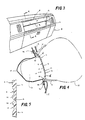
- the compartment 18 is provided to house an air bag 20 therein in an undeployed state. ( Figure 4 shows the air bag 20 in the deployed state).
- Grooves 8 and 10 include edges 22 and 24, respectively, which are disposed immediately adjacent the rupturable membrane 6 and are generally of a bead configuration.
- the beads 22 and 24 are provided so that sections 2 and 4 open along a predetermined path, thereby assuring proper exodus of air bag 20 upon its deployment.
- Grooves 8 and 10 cooperate with beads 22 and 24 in rupturing membrane 6.
- the grooves provide a more flexible area near membrane 6 thereby allowing maximum stress to be placed on the membrane when air bag 20 is inflated.
- Beads 22 and 24 act as a fulcrum placing additional stress on membrane 6 when bag 20 is inflating. (Devices necessary for deploying air bag 20 have been omitted for the sake of clarity).
- the patents cited above may be referred to for details of such devices.
- sections 2 and 4 are provided with generally S-shaped flexible hinges 26 and 28, respectively, which allow the sections 2 and 4 to pivot outwardly from each other when the rupturable membrane 6 is ruptured, as shown in broken lines in Figure 4.
- the thickness of the rupturable cover A is greater generally in the hinges 26 and 28 area and substantially lesser in the area of rupturable membrane 6.
- the rupturable cover A includes top and bottom flange portions 30 and 32, respectively, which remain hidden from view on the vehicle when rupturable cover A is mounted therein.
- the rupturable cover A is provided with a number of stake members 34 on the interior surface 12 on top and bottom flange portions 30 and 32.
- stake members 34 protrude through holes 36 in the compartment 18 of the vehicle, and are flattened (shown by solid lines in Figure 4) by applying heat or the like to thereby permanently mount the rupturable cover A on vehicle dashboard B.
- Rupturable cover A may be mounted directly on an air bag module which can be assembled as a unit in the dashboard of the vehicle.
- rupturable cover A may be mounted on the dashboard B by screws 35 or the like, instead of stakes 34, shown in Figure 8-10.
- the top and bottom flange portions 30 and 32 are provided with holes 38 through which screws 35 or the like may extend to be fastened with the compartment 18 of the vehicle.
- top and bottom flange portions 30 and 32 include laterally extending tabs 40 and 41, respectively, which extend past the hinges 26 and 28 and facilitate mounting of rupturable cover A on the vehicle.
- the side portions 42 and 44 of sections 2 and 4 have generally inwardly curved top and bottom edges 46 and 48, respectively, and are further rounded in configuration. Therefore, when the rupturable cover A is mounted on the dashboard B, side portions 42 and 44 hide the corresponding portions (not shown) of compartment 18.
- the grooves 50 and 52 generally extend the length of hinges 26 and 28 and accommodate corresponding portions of vehicle dashboard B in order to securely hold cover A thereon.
- grooves 50 and 52 disposed adjacent top portion 30 have substantially lesser depth ( Figure 6) than the grooves 50 and 52 disposed adjacent bottoms portion 32 ( Figure 7).
- the cover A further includes upper and lower furrows 51 and 53 disposed on the interior surface 12 thereof adjacent the area of top and bottom flange portion 30 and 32, respectively. Furrows 51 and 53, like grooves 50 and 52, also extend the length of hinges 26 and 28 and facilitate flush mounting of the cover A on dashboard B.
- tabs 41 extending from bottom flange portion 32 include an inwardly inclined bottom surface 43 to further facilitate secure mounting of cover A on the dashboard B.
- bottom surface 45 of tabs 40 extending from upper flange portion 30, are shown to be generally flat, it is well within the scope of this invention to make it inclined as surfaces 43 of tabs 41.
- the bottom flange portion 32 is further provided with recesses 54 (Figure 1) on the exterior surface 14 along the length thereof, which to receive a lower portion C of vehicle dashboard B therein for securely mounting the cover A on dashboard B.
- the top flange portion 30 may also likewise be provided with recesses 54 or the like for receiving an upper portion D of the vehicle dashboard B.
- the cover A as best shown in Figures 4, 6, and 7 may preferably be made so as to have a certain depth E, except in the top and bottom portions 30 and 32. This depth E is provided to flush-mount the cover A with the entire dashboard B of the vehicle.
- the rupturable cover of the present invention may preferably be made from a moldable thermoplastic polymeric material.
- a moldable thermoplastic polymeric material is Du Pont's "Hytrel” copolyether ester elastomer of the type disclosed in U.S. Patent 3,651,014. (Hytrel is a registered trademark of E. I. du Pont de Nemours and Company, Wilmington, Delaware).
- materials which may be used to make the present rupturable cover include polycarbonates, polyolefins, thermoplastic polyolefin alloys, polyurethanes, polyamides, polyacetals, thermoplastic polyester elastomers, polybutylene terephthalate, polyethylene terephthalate, acrylonitrile/butylene/styrene polymers and polystyrene.
- Air bag 20 is then extruded from its compartment 18 and expands in the shape of a large balloon which prevents the passenger from leaning forwardly.
Landscapes
- Engineering & Computer Science (AREA)
- Mechanical Engineering (AREA)
- Air Bags (AREA)
Claims (8)
Applications Claiming Priority (2)
| Application Number | Priority Date | Filing Date | Title |
|---|---|---|---|
| US238697 | 1988-08-31 | ||
| US07/238,697 US4895389A (en) | 1988-08-31 | 1988-08-31 | Rupturable cover for a vehicle air bag compartment |
Publications (2)
| Publication Number | Publication Date |
|---|---|
| EP0357356A1 EP0357356A1 (fr) | 1990-03-07 |
| EP0357356B1 true EP0357356B1 (fr) | 1992-06-17 |
Family
ID=22898950
Family Applications (1)
| Application Number | Title | Priority Date | Filing Date |
|---|---|---|---|
| EP89308667A Expired - Lifetime EP0357356B1 (fr) | 1988-08-31 | 1989-08-25 | Couvercle rompable pour compartiment de sac à air de véhicule |
Country Status (5)
| Country | Link |
|---|---|
| US (1) | US4895389A (fr) |
| EP (1) | EP0357356B1 (fr) |
| JP (1) | JPH02147452A (fr) |
| DE (1) | DE68901832T2 (fr) |
| ES (1) | ES2033528T3 (fr) |
Families Citing this family (49)
| Publication number | Priority date | Publication date | Assignee | Title |
|---|---|---|---|---|
| US4989896A (en) * | 1988-10-17 | 1991-02-05 | Tip Engineering Group, Inc. | Double door closure for an air bag deployment opening |
| DE3837085A1 (de) * | 1988-11-01 | 1990-05-03 | Kolbenschmidt Ag | Gassack-aufprallschutzvorrichtung |
| US5110647A (en) * | 1988-12-26 | 1992-05-05 | Takata Corporation | Cover for a vehicle air bag |
| DE3942694C3 (de) * | 1988-12-26 | 2003-05-15 | Takata Corp | Abdeckung für einen gefalteten Gassack einer Aufprallschutzvorrichtung in Kraftfahrzeugen |
| US5217244A (en) * | 1989-07-14 | 1993-06-08 | Tip Engineering Group | Arrangement for forming an air bag deployment opening |
| US5180187A (en) * | 1989-02-18 | 1993-01-19 | Daimler-Benz Ag | Cover for an airbag unit and the process for producing it |
| JPH0694266B2 (ja) * | 1989-02-20 | 1994-11-24 | タカタ株式会社 | エアバッグ収納用カバー |
| US5135253A (en) * | 1989-05-24 | 1992-08-04 | Mazda Motor Corporation | Air bag system for vehicle |
| EP0432766A3 (en) * | 1989-12-13 | 1992-03-18 | Union Carbide Chemicals And Plastics Company, Inc. | Air bag deployment door |
| JP2961780B2 (ja) * | 1989-12-18 | 1999-10-12 | タカタ株式会社 | エアーバッグ収納用カバー |
| JPH03279055A (ja) * | 1990-03-28 | 1991-12-10 | Mazda Motor Corp | 自動車のエアバッグ装置 |
| US5195776A (en) * | 1990-03-27 | 1993-03-23 | Mazda Motor Corporation | Air bag installation |
| GB2250295B (en) * | 1990-11-29 | 1994-02-02 | Asahi Chemical Ind | Cover for accommodating air bag in air bag system |
| US5121942A (en) * | 1991-01-22 | 1992-06-16 | Davidson Textron Inc. | Airbag cover assembly and method of forming same |
| WO1992014632A1 (fr) * | 1991-02-13 | 1992-09-03 | Allied-Signal Inc. | Couvercle pour airbag avec joint a dechirure |
| JPH05162607A (ja) * | 1991-12-17 | 1993-06-29 | Takata Kk | 助手席用エアバッグ装置のリッド |
| JPH05270338A (ja) * | 1992-03-25 | 1993-10-19 | Takata Kk | 助手席用エアバッグ装置のモジュールカバー取付構造 |
| JPH05319197A (ja) * | 1992-05-21 | 1993-12-03 | Takata Kk | 助手席用エアバッグ装置 |
| US5335935A (en) * | 1992-08-31 | 1994-08-09 | Plastic Mold Technology Incorporated | Air bag cover/molded article with integral cover layer of leather |
| DE69322337T2 (de) * | 1992-09-16 | 1999-07-15 | Toyoda Gosei Co., Ltd., Aichi | Abdeckung für einen Airbag |
| US5256354A (en) * | 1992-11-12 | 1993-10-26 | Davidson Textron Inc. | Method for forming an invisible tear seam |
| US5378014A (en) * | 1992-11-13 | 1995-01-03 | Davidson Textron Inc. | Dual door arrangement for air bag deployment |
| US5498026A (en) * | 1992-12-02 | 1996-03-12 | Larry J. Winget | Air bag cover having a hidden break seam |
| US5306040A (en) * | 1993-03-17 | 1994-04-26 | Morton International, Inc. | Cover for airbag |
| US5393089A (en) * | 1993-09-01 | 1995-02-28 | Chrysler Corporation | Vehicle air bag cover |
| US5445410A (en) * | 1994-06-13 | 1995-08-29 | Chrysler Corporation | Instrument panel assembly having hidden air bag door disposed laterally between vents |
| EP0783469B1 (fr) * | 1994-09-29 | 1998-07-01 | E.I. Du Pont De Nemours And Company | Dispositif permettant d'abaisser la teneur en monoxyde de carbone dans les coussins gonflables |
| US5460402A (en) * | 1995-01-27 | 1995-10-24 | Davidson Textron Inc. | Air bag cover door having a predetermined opening characteristic |
| US5533749A (en) * | 1995-09-07 | 1996-07-09 | Morton International, Inc. | Apparatus for improved detachment of the deployment door of an airbag assembly |
| GB9519847D0 (en) * | 1995-09-29 | 1995-11-29 | United Technologies Automotive | Crash protection device |
| DE19546585A1 (de) * | 1995-12-13 | 1997-06-19 | Trw Repa Gmbh | Gassack-Abdeckung für ein Fahrzeuginsassen-Rückhaltesystem sowie Verfahren zu deren Herstellung |
| US5741024A (en) * | 1996-05-31 | 1998-04-21 | Morton International, Inc. | Airbag module cover attachment and method of attaching a module cover to an airbag module |
| JP3321531B2 (ja) * | 1996-08-26 | 2002-09-03 | 株式会社イノアックコーポレーション | エアバッグドアを有するインストルメントパネル |
| DE69840821D1 (de) | 1997-03-26 | 2009-06-25 | Toyota Motor Co Ltd | Innenfahrzeugteile mit einer airbagaustrittsklappe und giessmethode dafür |
| US5863064A (en) * | 1997-08-14 | 1999-01-26 | Textron Autmotive Company Inc. | Skin for automotive air bag cover panel formed by casting different plastic materials |
| US6260875B1 (en) * | 1998-06-19 | 2001-07-17 | Textron Automotive Company | Seamless/integral DSIR or PSIR door configuration in hard plastic trim application facilitated by gas |
| DE19828001C1 (de) * | 1998-06-24 | 1999-07-15 | Daimler Chrysler Ag | Instrumententafel für ein Kraftfahrzeug |
| US6042140A (en) * | 1998-07-10 | 2000-03-28 | Larry J. Winget | Air bag cover having a visually perceptible tear seam |
| US6345837B1 (en) | 1998-11-05 | 2002-02-12 | Chrysler Corporation | Passenger side air bag module |
| EP1106445A1 (fr) * | 1999-12-10 | 2001-06-13 | ACTS-Advanced Car Technology Systems GmbH & Co.KG | Coussin de sécurité intégré dans une garniture de l'habitacle d'un véhicule automobile |
| US6431585B1 (en) | 2000-10-05 | 2002-08-13 | Lear Corporation | Dual stage fastener |
| US20060012153A1 (en) * | 2000-12-08 | 2006-01-19 | Acts Advanced Car Technology Systems Gmbh & Co. Kg | Airbag system for motor vehicle integrated in an inner trim piece |
| US6692019B2 (en) | 2001-03-13 | 2004-02-17 | Delphi Technologies, Inc. | Method to create invisible air bag deployment panel |
| US6644685B2 (en) | 2001-09-07 | 2003-11-11 | Visteon Global Technologies, Inc. | Seamless passenger side airbag door |
| US6565115B2 (en) | 2001-09-07 | 2003-05-20 | Visteon Global Technologies, Inc. | Invisible airbag door |
| US6623029B2 (en) * | 2001-09-07 | 2003-09-23 | Visteon Global Technologies, Inc. | Seamless passenger side airbag door on hard instrument panel |
| US7261314B2 (en) * | 2004-10-04 | 2007-08-28 | Autoliv Asp, Inc. | Airbag cover attachment and opening assembly |
| KR100646654B1 (ko) * | 2005-03-09 | 2006-11-23 | 주식회사 코오롱 | 굴곡특성이 우수한 열가소성 폴리에테르에스테르 엘라스토머 수지조성물 및 이로부터 제조된 차량용 에어백 장치용커버 |
| US7717916B2 (en) * | 2007-08-16 | 2010-05-18 | Nutek Orthopaedics, Inc. | External fixation apparatus with adjustable pin clamping means |
Family Cites Families (26)
| Publication number | Priority date | Publication date | Assignee | Title |
|---|---|---|---|---|
| US3539200A (en) * | 1967-10-12 | 1970-11-10 | Eaton Yale & Towne | Vehicle safety device |
| US3632135A (en) * | 1969-09-15 | 1972-01-04 | Eaton Yale & Towne | Reservoir in the steering column |
| US3640546A (en) * | 1969-09-15 | 1972-02-08 | Eaton Yale & Towne | Safety apparatus |
| US3756617A (en) * | 1969-09-15 | 1973-09-04 | Eaton Corp | Safety apparatus |
| US3622176A (en) * | 1970-02-05 | 1971-11-23 | Ford Motor Co | Motor vehicle instrument panel element |
| US3708179A (en) * | 1970-08-07 | 1973-01-02 | Mccord Corp | Door assembly |
| US3643971A (en) * | 1970-08-11 | 1972-02-22 | Allied Chem | Self-inflating impact-absorbing bag for vehicles |
| DE2109463C2 (de) * | 1971-02-27 | 1972-12-07 | Ford Werke Ag | Lenkrad mit Sicherheits-luftkissen insbesondere für Kraftfahrzeuge |
| US3778085A (en) * | 1971-10-06 | 1973-12-11 | M Lipkin | Concealed pneumatic safety system |
| GB1358364A (en) * | 1971-12-03 | 1974-07-03 | Daimler Benz Ag | Vehicle with automatically inflatable protective gas cushion |
| US3794349A (en) * | 1972-05-19 | 1974-02-26 | Gen Motors Corp | Occupant restraint system |
| US3819205A (en) * | 1972-09-25 | 1974-06-25 | Gen Motors Corp | Modular occupant restraint system |
| US3904222A (en) * | 1973-12-03 | 1975-09-09 | Gen Motors Corp | Occupant restraint system |
| US3966227A (en) * | 1974-10-24 | 1976-06-29 | General Motors Corporation | Cover assembly for an occupant restraint system |
| JPS5243233A (en) * | 1975-09-30 | 1977-04-05 | Nissan Motor Co Ltd | Cushion cover for air cushion device |
| US4120516A (en) * | 1975-12-05 | 1978-10-17 | Nissan Motor Company, Limited | Cover member for a safety air-cushion device and a method of producing the same |
| JPS52116537A (en) * | 1976-03-26 | 1977-09-30 | Toyota Motor Corp | Expansion type passenger restricting device for automobile or the like |
| DE2848547A1 (de) * | 1978-11-09 | 1980-05-22 | Daimler Benz Ag | Nach unten aufklappbare abdeckung fuer ein gefaltet angeordnetes gaskissen |
| DE2905618A1 (de) * | 1979-02-14 | 1980-08-21 | Daimler Benz Ag | Auf eine grundplatte aufklipsbare kappenartige abdeckung |
| DE3011463A1 (de) * | 1980-03-25 | 1981-10-08 | Repa Feinstanzwerk Gmbh, 7071 Alfdorf | Vorrichtung in kraftfahrzeugen fuer die halterung von zum schutze der fahrzeuginsassen angeordneten luftsaecken |
| US4332398A (en) * | 1980-07-11 | 1982-06-01 | General Motors Corporation | Inflatable restraint system |
| US4325568A (en) * | 1980-07-28 | 1982-04-20 | General Motors Corporation | Modular occupant restraint system |
| DE3116538A1 (de) * | 1981-04-25 | 1982-11-11 | Petri Ag, 8750 Aschaffenburg | Gehaeuse fuer gassack-aufprall-schutzeinrichtungen |
| DE3315535A1 (de) * | 1983-04-29 | 1984-03-22 | Daimler-Benz Ag, 7000 Stuttgart | Abdeckung fuer ein aufblasbares gaskissen |
| DE3544704A1 (de) * | 1985-12-18 | 1987-06-25 | Daimler Benz Ag | Aufprallschutzeinrichtung fuer die insassen eines kraftfahrzeuges |
| DE3811373A1 (de) * | 1987-04-06 | 1988-10-27 | Toyoda Gosei Kk | Polster fuer eine einen luftsack enthaltende vorrichtung |
-
1988
- 1988-08-31 US US07/238,697 patent/US4895389A/en not_active Expired - Fee Related
-
1989
- 1989-08-25 DE DE8989308667T patent/DE68901832T2/de not_active Expired - Lifetime
- 1989-08-25 EP EP89308667A patent/EP0357356B1/fr not_active Expired - Lifetime
- 1989-08-25 ES ES198989308667T patent/ES2033528T3/es not_active Expired - Lifetime
- 1989-08-31 JP JP1223359A patent/JPH02147452A/ja active Pending
Also Published As
| Publication number | Publication date |
|---|---|
| DE68901832T2 (de) | 1992-12-17 |
| US4895389A (en) | 1990-01-23 |
| DE68901832D1 (de) | 1992-07-23 |
| ES2033528T3 (es) | 1993-03-16 |
| JPH02147452A (ja) | 1990-06-06 |
| EP0357356A1 (fr) | 1990-03-07 |
Similar Documents
| Publication | Publication Date | Title |
|---|---|---|
| US4895389A (en) | Rupturable cover for a vehicle air bag compartment | |
| US4989896A (en) | Double door closure for an air bag deployment opening | |
| EP0573145B1 (fr) | Couvercle pour installation de sac gonflable | |
| EP0582443B1 (fr) | Couvercle pour loger un coussin pneumatique destiné à un générateur de gaz à haute puissance et charnière pour celui-ci | |
| US6672611B2 (en) | Air bag deployment chute and panel assembly | |
| US5524922A (en) | Energy dissipation features in air bag clousures | |
| EP0640514B1 (fr) | Rabat de retenue de sac gonflable déchirable | |
| US20030209888A1 (en) | Air bag assembly | |
| US5306040A (en) | Cover for airbag | |
| JP3039857U (ja) | エアバッグ展開用開口のための閉鎖要素 | |
| JPH06107102A (ja) | エアバッグ装置のパッド | |
| EP0714816B1 (fr) | Couvercle de déploiement pour utilisation dans un dispositif de retenue d'un occupant de véhicule | |
| US5722684A (en) | Hinged module cover | |
| EP0881129B1 (fr) | Moyen de fixation d'un couvercle de sac de sécurité gonflable | |
| JP2948849B2 (ja) | ガスバッグのカバー体 | |
| EP0754597B1 (fr) | Interrupteurs de fonction incorporés dans le couvercle d'un coussin d'air côté conducteur | |
| US6517101B1 (en) | Release assembly and method for deploying a supplemental restraint system | |
| KR100496690B1 (ko) | 조수석 에어백 전개를 위한 리액션플레이트 힌지 구조 | |
| JP3792297B2 (ja) | エアバッグ組立体のための閉鎖組立体 | |
| JPH1191474A (ja) | エアバッグカバー | |
| JP2002037000A (ja) | 助手席用エアバッグ装置 | |
| KR100499946B1 (ko) | 조수석 에어백 전개를 위한 도어플레이트 및리액션플레이트 힌지 구조 | |
| JP2025129640A (ja) | エアバッグ装置のカバー体 |
Legal Events
| Date | Code | Title | Description |
|---|---|---|---|
| PUAI | Public reference made under article 153(3) epc to a published international application that has entered the european phase |
Free format text: ORIGINAL CODE: 0009012 |
|
| AK | Designated contracting states |
Kind code of ref document: A1 Designated state(s): DE ES FR GB IT SE |
|
| 17P | Request for examination filed |
Effective date: 19900822 |
|
| 17Q | First examination report despatched |
Effective date: 19910402 |
|
| GRAA | (expected) grant |
Free format text: ORIGINAL CODE: 0009210 |
|
| AK | Designated contracting states |
Kind code of ref document: B1 Designated state(s): DE ES FR GB IT SE |
|
| ITF | It: translation for a ep patent filed | ||
| REF | Corresponds to: |
Ref document number: 68901832 Country of ref document: DE Date of ref document: 19920723 |
|
| ET | Fr: translation filed | ||
| REG | Reference to a national code |
Ref country code: ES Ref legal event code: FG2A Ref document number: 2033528 Country of ref document: ES Kind code of ref document: T3 |
|
| PLBE | No opposition filed within time limit |
Free format text: ORIGINAL CODE: 0009261 |
|
| STAA | Information on the status of an ep patent application or granted ep patent |
Free format text: STATUS: NO OPPOSITION FILED WITHIN TIME LIMIT |
|
| 26N | No opposition filed | ||
| EAL | Se: european patent in force in sweden |
Ref document number: 89308667.8 |
|
| PGFP | Annual fee paid to national office [announced via postgrant information from national office to epo] |
Ref country code: FR Payment date: 19960528 Year of fee payment: 8 |
|
| PGFP | Annual fee paid to national office [announced via postgrant information from national office to epo] |
Ref country code: DE Payment date: 19960610 Year of fee payment: 8 |
|
| PGFP | Annual fee paid to national office [announced via postgrant information from national office to epo] |
Ref country code: SE Payment date: 19960614 Year of fee payment: 8 |
|
| PGFP | Annual fee paid to national office [announced via postgrant information from national office to epo] |
Ref country code: GB Payment date: 19960620 Year of fee payment: 8 |
|
| PGFP | Annual fee paid to national office [announced via postgrant information from national office to epo] |
Ref country code: ES Payment date: 19960807 Year of fee payment: 8 |
|
| PG25 | Lapsed in a contracting state [announced via postgrant information from national office to epo] |
Ref country code: GB Free format text: LAPSE BECAUSE OF NON-PAYMENT OF DUE FEES Effective date: 19970825 |
|
| PG25 | Lapsed in a contracting state [announced via postgrant information from national office to epo] |
Ref country code: SE Free format text: LAPSE BECAUSE OF NON-PAYMENT OF DUE FEES Effective date: 19970826 Ref country code: ES Free format text: LAPSE BECAUSE OF NON-PAYMENT OF DUE FEES Effective date: 19970826 |
|
| GBPC | Gb: european patent ceased through non-payment of renewal fee |
Effective date: 19970825 |
|
| PG25 | Lapsed in a contracting state [announced via postgrant information from national office to epo] |
Ref country code: FR Free format text: LAPSE BECAUSE OF NON-PAYMENT OF DUE FEES Effective date: 19980430 |
|
| PG25 | Lapsed in a contracting state [announced via postgrant information from national office to epo] |
Ref country code: DE Free format text: LAPSE BECAUSE OF NON-PAYMENT OF DUE FEES Effective date: 19980501 |
|
| EUG | Se: european patent has lapsed |
Ref document number: 89308667.8 |
|
| REG | Reference to a national code |
Ref country code: FR Ref legal event code: ST |
|
| REG | Reference to a national code |
Ref country code: ES Ref legal event code: FD2A Effective date: 19980910 |
|
| PG25 | Lapsed in a contracting state [announced via postgrant information from national office to epo] |
Ref country code: IT Free format text: LAPSE BECAUSE OF NON-PAYMENT OF DUE FEES Effective date: 20050825 |