EP0357358B1 - Canon à électrons à support de filament renforcé muni de moyens de positionnement - Google Patents
Canon à électrons à support de filament renforcé muni de moyens de positionnement Download PDFInfo
- Publication number
- EP0357358B1 EP0357358B1 EP89308676A EP89308676A EP0357358B1 EP 0357358 B1 EP0357358 B1 EP 0357358B1 EP 89308676 A EP89308676 A EP 89308676A EP 89308676 A EP89308676 A EP 89308676A EP 0357358 B1 EP0357358 B1 EP 0357358B1
- Authority
- EP
- European Patent Office
- Prior art keywords
- heater
- feet
- reinforced
- tabs
- tab
- Prior art date
- Legal status (The legal status is an assumption and is not a legal conclusion. Google has not performed a legal analysis and makes no representation as to the accuracy of the status listed.)
- Expired - Lifetime
Links
Images


Classifications
-
- H—ELECTRICITY
- H01—ELECTRIC ELEMENTS
- H01J—ELECTRIC DISCHARGE TUBES OR DISCHARGE LAMPS
- H01J1/00—Details of electrodes, of magnetic control means, of screens, or of the mounting or spacing thereof, common to two or more basic types of discharge tubes or lamps
- H01J1/88—Mounting, supporting, spacing, or insulating of electrodes or of electrode assemblies
-
- H—ELECTRICITY
- H01—ELECTRIC ELEMENTS
- H01J—ELECTRIC DISCHARGE TUBES OR DISCHARGE LAMPS
- H01J29/00—Details of cathode-ray tubes or of electron-beam tubes of the types covered by group H01J31/00
- H01J29/02—Electrodes; Screens; Mounting, supporting, spacing or insulating thereof
- H01J29/04—Cathodes
-
- H—ELECTRICITY
- H01—ELECTRIC ELEMENTS
- H01J—ELECTRIC DISCHARGE TUBES OR DISCHARGE LAMPS
- H01J1/00—Details of electrodes, of magnetic control means, of screens, or of the mounting or spacing thereof, common to two or more basic types of discharge tubes or lamps
- H01J1/02—Main electrodes
- H01J1/13—Solid thermionic cathodes
- H01J1/15—Cathodes heated directly by an electric current
- H01J1/18—Supports; Vibration-damping arrangements
-
- H—ELECTRICITY
- H01—ELECTRIC ELEMENTS
- H01J—ELECTRIC DISCHARGE TUBES OR DISCHARGE LAMPS
- H01J29/00—Details of cathode-ray tubes or of electron-beam tubes of the types covered by group H01J31/00
- H01J29/46—Arrangements of electrodes and associated parts for generating or controlling the ray or beam, e.g. electron-optical arrangement
- H01J29/48—Electron guns
Definitions
- This invention relates to an electron gun assembly having a pair of reinforced heater tabs, each of which includes locating means to minimize cathode-ray tube, CRT, failure caused by a shorted conformal heater tab and to provide more accurate positioning of the conformal heater tab between the pair of reinforced heater tabs.
- U.S. Patent No. 3,555,640 issued to Lundvall on January 19, 1971, discloses a method for mounting a heater within a tubular cathode.
- a U-shaped tab is welded to the legs of the heater, and a transverse portion of the tab is removed after the heater is positioned within the tubular cathode. The removal of the transition portion electrically isolates the arms of the tab so that the heater can be energized.
- the tab is shown as substantially flat.
- a step-like offset of the heater tab is shown in U.S. Patent No. 4,523,124, issued to Blanken et al. on June 11, 1985. The offset facilitates centering of the heater within the tubular cathode and permits thermal expansion of the tab structure during tube operation, but provides little structural strength.
- U.S. Patent No. 4,789,807 issued to Hale on December 6, 1988, discloses an inline electron gun assembly having at least one reinforced heater tab and, preferably, a pair of reinforced heater tabs which support and position the heaters for the outer cathodes of the inline electron gun.
- the reinforced heater tabs include each a main body portion, a pair of orthogonal legs extending from opposite sides of the main body portion, and a pair of feet directed outwardly from the legs. Triangular gussets are formed between the main body portion and the legs and between the legs and the feet.
- each of the reinforced heater tabs are attached to the distal ends of oppositely disposed heater bead straps, the proximal ends of which are embedded into insulative support beads of the electron gun.
- the reinforced heater tabs are mutually parallel and provide a box-like structure with the support beads.
- a conformal heater tab i.e., a heater tab without any reinforcing structure, is disposed perpendicularly to and attached between the reinforced heater tabs, preferably by welding.
- the feet of the conformal heater tab are attached each to one of the legs of both of the reinforced heater tabs, to properly position the heater for the center cathode within the tubular center cathode.
- a drawback of this structure is that the feet of the conventional heater tab can be positioned anywhere along the legs of the reinforced heater tabs, and occasionally on one or both of the reinforcing gussets connecting the main body portion and the legs. Such misalignment of the conformal heater tab can result in the cathode heater contacting the tubular cathode sleeve, heat-sinking the heater. If the feet of the conformal heater tab are on the reinforcing gussets, poor welding can occur, which may result either in an open heater circuit or in weld-generated particles (i.e., weld-splash) within the electron gun.
- an electron gun assembly for use in a color cathode-ray tube, said gun assembly including a pair of insulating support rods, three inline indirectly heated cathodes including a center cathode and two outer cathodes for generating three electron beams, attachment means for attaching said cathodes to said support rods, a heater for each of said cathodes, each said heater having a pair of heater legs, a pair of reinforced heater tabs associated with said outer cathode and a conformal heater tab associated with said center cathode, each of said heater tabs having a main body portion including a first and a second part, each of said parts being attached to a respective leg of one of said heaters, each of said heater tabs having a pair of outwardly directed feet, each of said feet being connected to a respective part of the parts of the main body portion by a pair of orthogonal legs extending therebetween, said reinforced heater tabs including a first reinforcing structure extending between said
- FIGURE 1 is a broken away, side elevational view of an electron gun assembly incorporating the present invention.
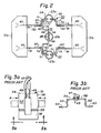
- FIGURE 2 is a bottom view, along section line 2-2, showing a first embodiment of nested heater tabs of the electron gun of FIGURE 1.
- FIGURES 3a and 3b are plan and bottom views, respectively, of a conventional conformal heater tab during electron gun construction.
- FIGURES 4a, 4b and 4c show a first embodiment of a reinforced heater tab according to the present invention, during electron gun construction.
- FIGURE 5 is a bottom view showing a second embodiment of nested heater tabs of the electron gun of FIGURE 1.
- FIGURE 1 shows structural details of an inline electron gun 11 mounted in a neck 13 of a color cathode-ray tube, CRT.
- the CRT includes an evacuated glass envelope having a rectangular faceplate panel (not shown) and a funnel (also not shown), with a neck 13 integrally attached to the funnel.
- a base 19 is attached to the stem 15 and serves to locate and support the leads 17.
- the inline electron gun 11 is centrally mounted within the neck 13 and is designed to generate and direct three electron beams along spaced, substantially co-planar, convergent paths towards a screen (not shown) on the faceplate panel.
- the gun assembly comprises two insulating glass support rods 21a and 21b from which various electrodes are supported to form a coherent unit, in a manner well known in the art.
- These electrodes include three substantially equally transversely-spaced co-planar indirectly heated cathodes 23 (one for producing each beam), a control grid electrode 25 (also referred to as G1), a screen grid electrode 27 (also referred to as G2), a first accelerating and focusing electrode 29 (also referred to as G3) and a second accelerating and focusing electrode 31 (also referred to as G4), longitudinally spaced, in the order named, along the support rods 21a and 21b.
- a shield cup 33 is attached to the G4 electrode 31.
- the various electrodes of the gun assembly 11, excluding the G4 electrode are electrically connected to the pins 17 either directly or through metal ribbons 35.
- the gun assembly 11 is centered within the neck 13 by snubbers 37 on the shield cup 33, which press on and make contact with an electrically conductive internal coating 39 on the inside surface of the neck 13.
- the internal coating 39 extends over the inner surface of the funnel and connects to an anode button (not shown).
- a getter assembly 41 comprises an elongated spring 43, which is attached at one end to the cup 33 and extends in cantilever fashion into the funnel of the envelope.
- a metal getter container 45 is attached to the other extended end of the spring 43.
- the three cathodes 23 are substantially identical and comprise a cylinder closed at one end by a cap with a suitable electron emissive coating thereon.
- a heater 47 having a pair of heater legs 49, is disposed within each of the cathodes 23.
- the heater legs are attached, for example by welding, to a plurality of heater tabs.
- a pair of reinforced heater tabs 50 are associated with the outer cathodes 23a and 23c, and a conventional, conformal heater tab 51 is associated with the center cathode 23b.
- the conformal tab 51 comprises a main body portion 52 including a first part 54 and a second part 56 which are temporarily connected, during electron gun construction, by a removal portion 58 located below a score line 59.
- the conformal tab 51 includes a pair of outwardly directed feet 60, each of which is connected to the parts 54 and 56 of the main body portion 52 by substantially orthogonal legs 62 extending therebetween.
- the pair of heater legs 49 for the heater 47 are attached, for example by welding, to the parts 54 and 56.
- the novel reinforced heater tab 50 is similar to the conformal heater tab 51 (FIGURES 3a and 3b), and corresponding elements of the reinforced tab 50 are designated by the same numbers as used for the conformal tab 51.
- the reinforced heater tab 50 is different from the conformal tab 51 in that the reinforced tab 50 includes a first reinforcing structure comprising a first pair of oppositely disposed substantially rectangular first depressions 71, formed between and comprising a segment of the two parts 54 and 56 of the main body portion 52 and the orthogonal legs 62; and a second reinforcing structure comprising a pair of oppositely disposed gussets 73 formed at about a 45° angle between and comprising a segment of the orthogonal legs 62 and the feet 60.
- the rectangular first depressions 71 include each a first endwall portion 75 and a second endwall portion 77.
- the first endwall portion 75 is substantially perpendicular to the orthogonal legs 62 and acts as a first locating means for the feet 60 of the conformal heater tab 51, as shown in FIGURE 2.
- the second endwall portion 77 is substantially perpendicular to the main body portion 52 and to the first endwall portion 75.
- the reinforced heater tab 50 is formed of 0.20 mm thick 304 stainless steel or nickel-iron.
- Each of the reinforcing structures 71 and 73 has a width of about 0.38 mm.
- the structures 71 and 73 reinforce the tab 50 by strengthening the interconnection between the parts 54 and 56 of the main body portion 52 and the orthogonal legs 62, and between the legs 62 and the attached feet 60.
- the reinforced tab 50 is more rigid and resistant to transverse motion in the direction A′-A′ than the conformal tab 51, and thus is less likely to permit a heater short resulting from contact between the parts 54 and 56.
- the reinforced heater tab 50 also includes a stamped portion 79, shown in FIGURES 4a and 4c, formed in one surface of each of the feet 60.
- the stamped portions 79 extend for a distance of about 0.08 mm into each of the feet 60 and flatten the feet, to provide mechanical stability to the tab 50 without creating a protuberance on the opposite surface of each of the feet 60.
- the flattening facilitates attachment of the feet 60 of the tab 50 to a plurality of heater bead straps 81, which are shown in FIGURE 2.
- a proximal end 83 of each of the heater bead straps 81 is embedded into one of the insulating support rods 21a and 21b.
- the reinforced heater tabs 50 extend between oppositely disposed pairs of heater bead straps 81.
- the stamped portions 79 provide flat surfaces on the feet 60 to permit planar-to-planar contact between the feet 60 and the distal ends of the heater bead straps 81 and splash-free welding of the contacting components.
- the reinforced (outer cathode) heater tabs 50 which are welded to the heater bead straps 81, provide a substantially rigid, box-like support structure (see FIGURE 2) for the attachment of the conformal (center cathode) heater tab 51.
- the conformal heater tab 51 associated with the center cathode 23b, is a compliant structure without the reinforcing structures present in heater tabs 50.
- the conformal heater tab 51 has one foot 60 attached to a leg 62 of one of the heater tabs 50 and the other foot 60 attached to a leg 62 of the other heater tab 50.
- the conformal heater tab 51 associated with the center cathode 23b, accommodates to the configuration of the reinforced heater tabs 50 without distorting the nested arrangement of the heater tabs 50 and 51.
- the feet 60 of the conformal heater tab are shortened to provide an overall tab width of about 8.64mm, compared to an overall tab width of about 10.41mm for the reinforced heater tabs 50.
- the removal portions 58 (FIGURES 3a, 4a and 4c) of the heater tabs are detached at the score lines 59.
- the orientation of the parts 54 and 56 of the conformal heater tab 51 in a plane substantially parallel to the planes of the support rods 21a and 21b minimizes the compression on the conformal tab 50 and decreases the probability that the two parts 54 and 56 will experience a transverse motion that will cause the parts to contact one another. Accordingly, there is little likelihood that the nested heater tab structure of FIGURE 2 will short-out.
- FIGURE 5 A second embodiment of a novel reinforced heater tab is shown in FIGURE 5.
- the second reinforced heater tab 150 is similar in all respects to the novel first reinforced heater tab 50, except that the second reinforcing structure, between the orthogonal legs 62 and the feet 60, comprises a substantially rectangular second depression 73′ which includes a third endwall portion 85 and a fourth endwall portion 87.
- the third endwall portion 85 is substantially perpendicular to the feet 60 and acts as a second locating means for positioning the feet on the heater beads straps 81 to facilitate the interconnection thereof.
- the fourth endwall portion 87 is perpendicular to the orthogonal legs 62 and to the third endwall portion 85.
- the size of the second depression 73′ is identical to that of the first depression 71.
Landscapes
- Electrodes For Cathode-Ray Tubes (AREA)
- Solid Thermionic Cathode (AREA)
- Vessels, Lead-In Wires, Accessory Apparatuses For Cathode-Ray Tubes (AREA)
Claims (6)
- Système de canons électroniques devant être utilisé dans un tube couleur à rayons cathodiques, ledit système de canons comprenant une paire de tiges de support isolantes, trois cathodes en ligne, indirectement chauffées comprenant une cathode centrale et deux cathodes extérieures pour générer trois faisceaux électroniques, des moyens de fixation pour fixer lesdites cathodes auxdites tiges de support, un moyen de chauffage pour chacune desdites cathodes, chacun desdits moyens de chauffage ayant une paire de pattes de système de chauffage, une paire d'attaches de système de chauffage renforcées, associées à ladite cathode extérieure et une attache de conformité de système de chauffage associée à ladite cathode centrale, chaque attache du système de chauffage présentant un corps principal ayant une première et une seconde parties, chacune desdites parties étant fixée à une patte respective de l'un desdits systèmes de chauffage, chacune desdites attaches du système de chauffage comportant une paire de pieds dirigés vers l'extérieur, chacun desdits pieds étant connecté à une partie respective des parties dudit corps principal à l'aide d'une paire de pattes orthogonales s'étendant entre eux, lesdites attaches renforcées du système de chauffage comprenant une première structure de renfort s'étendant entre lesdites parties dudit corps principal et lesdites pattes orthogonales et également une seconde structure de renfort s'étendant entre lesdites pattes orthogonales et lesdits pieds, afin de maintenir la rigidité de ladite attache renforcée de système de chauffage, des paires d'étriers de cordons de système de chauffage, disposées de façon opposée et fixées auxdites tiges de support, lesdits pieds desdites attaches renforcées du système de chauffage étant fixés à une paire différente desdites paires opposées d'étriers de cordons de système de chauffage afin d'obtenir une structure essentiellement rigide, du type boîte, lesdits pieds de l'attache de conformité du système de chauffage étant fixés à l'une desdites pattes orthogonales de chacune desdites attaches renforcées du système de chauffage et ladite attache de conformité du système de chauffage étant disposée entre lesdites attaches renforcées du système de chauffage ;
caractérisé en ce que ladite première structure de renfort comprend une première partie en dépression sensiblement rectangulaire (71), interconnectant chacune desdites première (54) et seconde (56) parties dudit corps principal (52) et lesdites pattes orthogonales (62), chaque première partie en dépression comprenant une première paroi d'extrémité (75) sensiblement perpendiculaire auxdites pattes orthogonales et constituant des premiers moyens de positionnement desdits pieds (60) de ladite attache de conformité (51) du système de chauffage sur lesdites pattes orthogonales de chaque attache renforcée (150, 50) du système de chauffage. - Système de canons électroniques selon la revendication 1, caractérisé en ce que ladite première partie en dépression rectangulaire (71) est réalisée dans un segment de chacune desdites première (54) et seconde (56) parties dudit corps principal (52) et desdites pattes orthogonales (62).
- Système de canons électroniques selon la revendication 1, caractérisé en ce que chaque première partie en dépression (71) comprend une seconde paroi d'extrémité (77) sensiblement perpendiculaire audit corps principal (52) et à ladite première paroi d'extrémité.
- Système de canons électroniques selon la revendication 1, caractérisé en ce que ladite seconde structure de renfort comprend : une seconde partie en dépression (73′) sensiblement rectangulaire, interconnectant chacune des pattes orthogonales (62) et lesdits pieds (60) desdites attaches renforcées de système de chauffage (150), chaque seconde partie en dépression comprenant des seconds moyens de positionnement (85) pour positionner lesdits pieds desdites attaches renforcées de système de chauffage par rapport auxdites paires d'étriers de cordons (81) du système de chauffage.
- Système de canons électroniques selon la revendication 4, caractérisé en ce que ladite seconde partie en dépression (73′) est formée dans un segment de chacune desdites pattes orthogonales (62) et desdits pieds (60) desdites attaches renforcées (150) du système de chauffage.
- Système de canons électroniques selon la revendication 4, caractérisé en ce que lesdits seconds moyens de positionnement comportent une troisième paroi d'extrémité (85) de ladite seconde partie en dépression (73′), sensiblement perpendiculaire auxdits pieds (60) desdites attaches renforcées (150) de système de chauffage.
Applications Claiming Priority (2)
| Application Number | Priority Date | Filing Date | Title |
|---|---|---|---|
| US07/238,079 US4931691A (en) | 1988-08-30 | 1988-08-30 | Electron gun assembly having a reinforced heater tab with locating means |
| US238079 | 1988-08-30 |
Publications (3)
| Publication Number | Publication Date |
|---|---|
| EP0357358A2 EP0357358A2 (fr) | 1990-03-07 |
| EP0357358A3 EP0357358A3 (fr) | 1991-07-03 |
| EP0357358B1 true EP0357358B1 (fr) | 1995-06-07 |
Family
ID=22896406
Family Applications (1)
| Application Number | Title | Priority Date | Filing Date |
|---|---|---|---|
| EP89308676A Expired - Lifetime EP0357358B1 (fr) | 1988-08-30 | 1989-08-25 | Canon à électrons à support de filament renforcé muni de moyens de positionnement |
Country Status (12)
| Country | Link |
|---|---|
| US (1) | US4931691A (fr) |
| EP (1) | EP0357358B1 (fr) |
| JP (1) | JPH0673281B2 (fr) |
| KR (1) | KR0144148B1 (fr) |
| CN (1) | CN1017482B (fr) |
| CA (1) | CA1312909C (fr) |
| DD (1) | DD287355A5 (fr) |
| DE (1) | DE68922943T2 (fr) |
| ES (1) | ES2072906T3 (fr) |
| PL (1) | PL161862B1 (fr) |
| RU (1) | RU2010387C1 (fr) |
| TR (1) | TR24558A (fr) |
Families Citing this family (7)
| Publication number | Priority date | Publication date | Assignee | Title |
|---|---|---|---|---|
| KR910005186Y1 (ko) * | 1989-06-05 | 1991-07-20 | 삼성전관 주식회사 | 음극선관용 전자총의 히이터 지지구조 |
| KR930005826Y1 (ko) * | 1991-04-04 | 1993-08-27 | 삼성전관 주식회사 | 전자총용 히이터 지지체 |
| KR940005498B1 (ko) * | 1991-12-30 | 1994-06-20 | 삼성전관 주식회사 | 음극선관용 전자총의 히이터 지지체 |
| KR100249574B1 (ko) * | 1992-03-27 | 2000-03-15 | 요트.게.아. 롤페즈 | 전자총을 구비한 칼라 표시관 |
| KR100506646B1 (ko) * | 2002-07-22 | 2005-08-03 | 현대모비스 주식회사 | 차량 라디에이터 상부 마운팅 구조 |
| RU2590891C1 (ru) * | 2015-02-26 | 2016-07-10 | Общество С Ограниченной Ответственностью "Твинн" | Электронная отпаянная пушка для вывода электронного потока из вакуумной области пушки в атмосферу или иную газовую среду |
| CN115529710B (zh) * | 2022-09-28 | 2024-02-20 | 中国原子能科学研究院 | 一种电子帘加速器 |
Family Cites Families (10)
| Publication number | Priority date | Publication date | Assignee | Title |
|---|---|---|---|---|
| US3555640A (en) * | 1968-09-24 | 1971-01-19 | Rca Corp | Method of mounting a heater in a tubular cathode |
| US3973163A (en) * | 1975-09-02 | 1976-08-03 | Gte Sylvania Incorporated | Heater support positioning in a CRT electron generating assembly |
| US4049991A (en) * | 1976-10-08 | 1977-09-20 | Gte Sylvania Incorporated | Longitudinal rib embossment in tri-apertured, substantially planar electrode |
| JPS54144170A (en) * | 1978-05-02 | 1979-11-10 | Hitachi Ltd | Cathode constituent of direct heating type |
| NL8002343A (nl) * | 1980-04-23 | 1981-11-16 | Philips Nv | Elektronenkanon en kathodestraalbuis bevattende een dergelijk elektronenkanon. |
| NL8103814A (nl) * | 1981-08-14 | 1983-03-01 | Philips Nv | Kathodestraalbuis. |
| US4484102A (en) * | 1982-03-02 | 1984-11-20 | Rca Corporation | Strengthening means for a deep-drawn in-line electron gun electrode |
| US4486685A (en) * | 1982-05-14 | 1984-12-04 | Rca Corporation | Electron gun assembly with bead strap having an angulated grasping member |
| US4595858A (en) * | 1984-12-03 | 1986-06-17 | Rca Corporation | Reinforcing means for a cup-shaped electron gun electrode |
| US4789807A (en) * | 1987-08-31 | 1988-12-06 | Rca Licensing Corp. | Electron gun assembly having a reinforced heater tab |
-
1988
- 1988-08-30 US US07/238,079 patent/US4931691A/en not_active Expired - Lifetime
-
1989
- 1989-07-20 CA CA000606261A patent/CA1312909C/fr not_active Expired - Lifetime
- 1989-08-25 EP EP89308676A patent/EP0357358B1/fr not_active Expired - Lifetime
- 1989-08-25 TR TR89/0678A patent/TR24558A/xx unknown
- 1989-08-25 DE DE68922943T patent/DE68922943T2/de not_active Expired - Lifetime
- 1989-08-25 ES ES89308676T patent/ES2072906T3/es not_active Expired - Lifetime
- 1989-08-29 CN CN89106926A patent/CN1017482B/zh not_active Expired
- 1989-08-29 PL PL89281193A patent/PL161862B1/pl unknown
- 1989-08-29 RU SU894614973A patent/RU2010387C1/ru active
- 1989-08-29 DD DD89332165A patent/DD287355A5/de not_active IP Right Cessation
- 1989-08-29 JP JP1224319A patent/JPH0673281B2/ja not_active Expired - Lifetime
- 1989-08-30 KR KR1019890012370A patent/KR0144148B1/ko not_active Expired - Fee Related
Also Published As
| Publication number | Publication date |
|---|---|
| HK1004028A1 (en) | 1998-11-13 |
| PL161862B1 (pl) | 1993-08-31 |
| KR0144148B1 (ko) | 1998-07-01 |
| JPH02106853A (ja) | 1990-04-18 |
| CA1312909C (fr) | 1993-01-19 |
| US4931691A (en) | 1990-06-05 |
| EP0357358A2 (fr) | 1990-03-07 |
| CN1040705A (zh) | 1990-03-21 |
| RU2010387C1 (ru) | 1994-03-30 |
| JPH0673281B2 (ja) | 1994-09-14 |
| EP0357358A3 (fr) | 1991-07-03 |
| KR900003944A (ko) | 1990-03-27 |
| DE68922943D1 (de) | 1995-07-13 |
| DE68922943T2 (de) | 1995-12-21 |
| ES2072906T3 (es) | 1995-08-01 |
| CN1017482B (zh) | 1992-07-15 |
| DD287355A5 (de) | 1991-02-21 |
| TR24558A (tr) | 1991-11-22 |
Similar Documents
| Publication | Publication Date | Title |
|---|---|---|
| US4931691A (en) | Electron gun assembly having a reinforced heater tab with locating means | |
| EP0019975A1 (fr) | Tube image de télévision en couleurs | |
| EP0306247B1 (fr) | Structure avec canon d'électrons ayant une pièce de jonction renforcée pour élément de chauffage | |
| US4484102A (en) | Strengthening means for a deep-drawn in-line electron gun electrode | |
| US4720654A (en) | Modular electron gun for a cathode-ray tube and method of making same | |
| JP3649744B2 (ja) | テンションマスクフレーム用ディテンションロッドアセンブリを有する陰極線管 | |
| HK1004028B (en) | Electron gun assembly having a reinforced heater tab with locating means | |
| US4595858A (en) | Reinforcing means for a cup-shaped electron gun electrode | |
| US4992698A (en) | Color picture tube including an electron gun with an electrode having an optimized attachment means | |
| CA1183572A (fr) | Appareil de sertissage en perles pour la fabrication de canons electroniques avec tiges de support isolantes a auto-positionnement | |
| KR0141594B1 (ko) | 음극선관용 전자총 기구 | |
| JPH0119798Y2 (fr) | ||
| JPH08129977A (ja) | ゲッタースプリング及びこれを使用した陰極線管 | |
| JPS585309Y2 (ja) | サツゾウカン | |
| HK1004029B (en) | Color picture tube including an electron gun with an electrode having an optimized attachment means | |
| JPS60182647A (ja) | カラ−ブラウン管用電子銃 | |
| KR980009638U (ko) | 전자총의 지지 조정부재 | |
| JP2003016965A (ja) | 管内用抵抗器並びにその製造方法及びカラー陰極線管 |
Legal Events
| Date | Code | Title | Description |
|---|---|---|---|
| PUAI | Public reference made under article 153(3) epc to a published international application that has entered the european phase |
Free format text: ORIGINAL CODE: 0009012 |
|
| AK | Designated contracting states |
Kind code of ref document: A2 Designated state(s): DE ES FR GB IT |
|
| PUAL | Search report despatched |
Free format text: ORIGINAL CODE: 0009013 |
|
| AK | Designated contracting states |
Kind code of ref document: A3 Designated state(s): DE ES FR GB IT |
|
| 17P | Request for examination filed |
Effective date: 19911216 |
|
| 17Q | First examination report despatched |
Effective date: 19931220 |
|
| GRAA | (expected) grant |
Free format text: ORIGINAL CODE: 0009210 |
|
| AK | Designated contracting states |
Kind code of ref document: B1 Designated state(s): DE ES FR GB IT |
|
| ITF | It: translation for a ep patent filed | ||
| ET | Fr: translation filed | ||
| REF | Corresponds to: |
Ref document number: 68922943 Country of ref document: DE Date of ref document: 19950713 |
|
| REG | Reference to a national code |
Ref country code: ES Ref legal event code: FG2A Ref document number: 2072906 Country of ref document: ES Kind code of ref document: T3 |
|
| PLBE | No opposition filed within time limit |
Free format text: ORIGINAL CODE: 0009261 |
|
| STAA | Information on the status of an ep patent application or granted ep patent |
Free format text: STATUS: NO OPPOSITION FILED WITHIN TIME LIMIT |
|
| 26N | No opposition filed | ||
| REG | Reference to a national code |
Ref country code: GB Ref legal event code: IF02 |
|
| PGFP | Annual fee paid to national office [announced via postgrant information from national office to epo] |
Ref country code: ES Payment date: 20080922 Year of fee payment: 20 Ref country code: DE Payment date: 20080825 Year of fee payment: 20 |
|
| PGFP | Annual fee paid to national office [announced via postgrant information from national office to epo] |
Ref country code: IT Payment date: 20080827 Year of fee payment: 20 Ref country code: FR Payment date: 20080822 Year of fee payment: 20 |
|
| PGFP | Annual fee paid to national office [announced via postgrant information from national office to epo] |
Ref country code: GB Payment date: 20080718 Year of fee payment: 20 |
|
| REG | Reference to a national code |
Ref country code: GB Ref legal event code: PE20 Expiry date: 20090824 |
|
| REG | Reference to a national code |
Ref country code: ES Ref legal event code: FD2A Effective date: 20090826 |
|
| PG25 | Lapsed in a contracting state [announced via postgrant information from national office to epo] |
Ref country code: GB Free format text: LAPSE BECAUSE OF EXPIRATION OF PROTECTION Effective date: 20090824 |
|
| PG25 | Lapsed in a contracting state [announced via postgrant information from national office to epo] |
Ref country code: ES Free format text: LAPSE BECAUSE OF EXPIRATION OF PROTECTION Effective date: 20090826 |