EP0357384B1 - An image forming apparatus - Google Patents
An image forming apparatus Download PDFInfo
- Publication number
- EP0357384B1 EP0357384B1 EP89308745A EP89308745A EP0357384B1 EP 0357384 B1 EP0357384 B1 EP 0357384B1 EP 89308745 A EP89308745 A EP 89308745A EP 89308745 A EP89308745 A EP 89308745A EP 0357384 B1 EP0357384 B1 EP 0357384B1
- Authority
- EP
- European Patent Office
- Prior art keywords
- developing device
- door
- opening
- main assembly
- image forming
- Prior art date
- Legal status (The legal status is an assumption and is not a legal conclusion. Google has not performed a legal analysis and makes no representation as to the accuracy of the status listed.)
- Expired - Lifetime
Links
- 230000008878 coupling Effects 0.000 claims description 7
- 238000010168 coupling process Methods 0.000 claims description 7
- 238000005859 coupling reaction Methods 0.000 claims description 7
- 230000009471 action Effects 0.000 claims description 6
- 230000005540 biological transmission Effects 0.000 claims 2
- 239000000463 material Substances 0.000 description 42
- 230000015572 biosynthetic process Effects 0.000 description 15
- 238000007599 discharging Methods 0.000 description 7
- 230000007246 mechanism Effects 0.000 description 4
- 238000005192 partition Methods 0.000 description 4
- 238000000034 method Methods 0.000 description 2
- 230000008569 process Effects 0.000 description 2
- 238000004140 cleaning Methods 0.000 description 1
- 239000011521 glass Substances 0.000 description 1
- 238000010438 heat treatment Methods 0.000 description 1
- 238000012986 modification Methods 0.000 description 1
- 230000004048 modification Effects 0.000 description 1
- 230000003287 optical effect Effects 0.000 description 1
- 238000000926 separation method Methods 0.000 description 1
Images


Classifications
-
- G—PHYSICS
- G03—PHOTOGRAPHY; CINEMATOGRAPHY; ANALOGOUS TECHNIQUES USING WAVES OTHER THAN OPTICAL WAVES; ELECTROGRAPHY; HOLOGRAPHY
- G03G—ELECTROGRAPHY; ELECTROPHOTOGRAPHY; MAGNETOGRAPHY
- G03G15/00—Apparatus for electrographic processes using a charge pattern
- G03G15/01—Apparatus for electrographic processes using a charge pattern for producing multicoloured copies
- G03G15/0105—Details of unit
- G03G15/0126—Details of unit using a solid developer
-
- G—PHYSICS
- G03—PHOTOGRAPHY; CINEMATOGRAPHY; ANALOGOUS TECHNIQUES USING WAVES OTHER THAN OPTICAL WAVES; ELECTROGRAPHY; HOLOGRAPHY
- G03G—ELECTROGRAPHY; ELECTROPHOTOGRAPHY; MAGNETOGRAPHY
- G03G15/00—Apparatus for electrographic processes using a charge pattern
- G03G15/06—Apparatus for electrographic processes using a charge pattern for developing
- G03G15/08—Apparatus for electrographic processes using a charge pattern for developing using a solid developer, e.g. powder developer
- G03G15/0896—Arrangements or disposition of the complete developer unit or parts thereof not provided for by groups G03G15/08 - G03G15/0894
Definitions
- the present invention relates to an image forming apparatus wherein a developing device for developing an electrostatic latent image is exchangeable.
- color image forming apparatus There is an increasing demand for color image forming apparatus. To meet this demand, various measures have been proposed.
- Several types of color image forming apparatus are known.
- a process cartridge containing a developing device alone or containing an image bearing member in the form of a photosensitive drum, cleaning device, charging device and a developing device as a unit is detachably mountable into an image forming apparatus.
- the image forming apparatus is equipped with two developing device containing different color developers, which are selectively usable.
- the image forming apparatus is equipped with a number of developing device containing different color developers (what is called full-color type), from which a desired developing device is selectable.
- Apparatus of the first type referred to above is disclosed in GB-A-2141949 and GB-A-2150863.
- Apparatus of the second type referred to above is disclosed in GB-A-2174930.
- Apparatus of the third type referred to above is disclosed in GB-A-2165776.
- Apparatus as shown in Figure 1 is disclosed in EP-A-0271209.
- an image forming apparatus wherein wherein a developing device for developing a latent image is exchangeable, comprising: an opening for permitting mounting and dismounting of the developing device relative to a main assembly of the image forming apparatus; a path along which the developing device is movable between the opening and a predetermined position in the main assembly; a movable door for opening and closing said opening; and means for mechanically coupling said door and developing device to move the developing device along the path in association with opening and closing action of said door, is characterized in that the apparatus further comprises movable manual operating means comprising a hook movable, in association with opening and closing action of said door, toward and away from a portion of the developing device which is engageable with the hook, and a grip for manually retracting the developing device to outside of said opening and for pushing it into the main assembly through said opening to a position where said coupling means engages with the developing device.
- movable manual operating means comprising a hook movable, in association with opening and closing action of said door, toward and away from a
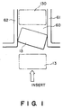
- Figure 1 illustrates the developing device stack by the wall.
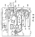
- Figure 2 is a sectional view of an image forming apparatus according to an embodiment of the present invention.
- Figure 3 is a perspective view of a major part of the image forming apparatus of Figure 2.
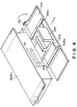
- Figure 4 is a perspective view of a major part of the image forming apparatus of Figure 2.
- Figure 5 is a sectional view of the image forming apparatus of Figure 2 to which plural developing device accommodating unit is attached.
- an image forming apparatus according to an embodiment of the present invention.
- an original 2 placed on an original supporting platen glass 1 is illuminated by a lamp 3.
- the reflected light image of the original is projected onto an electrophotographic photosensitive member (image bearing member) 11 through an optical system comprising reflection mirrors 4, 5, 6, 7, 8 and 9 and resume lens 10.
- the lamp 3, mirror 4, mirror 5 and mirror 6 are moved in the direction indicated by an arrow A at predetermined speeds to scan the original 2.
- the surface of the photosensitive drum 11 is uniformly charged by a primary charger 12 and is rotating in the direction indicated by an arrow B. Therefore, an electrostatic latent image corresponding to the original image is formed on the outer surface of the photosensitive drum 11.
- a chromatic developing device green developing device 13C
- color toner green, for example
- black developing device 14 containing black toner.
- Each of the developing devices 13C and 14 is movable in the direction indicated by an arrow C or C′ between a stand-by position and a developing position where it supplies the toner to the drum to develop the latent image.
- One of the developing devices selected in accordance with a desired color of the image is moved toward the photosensitive drum 11 to its developing position to develop the electrostatic latent image and photosensitive drum 11.
- the chromatic color developing device (green developing device 13C) is away, and the black developing device 14 is close to the photosensitive drum, therefore, a black image is formed on the photosensitive drum 11.
- the image is transferred onto a transfer material (transfer sheet) 17 by a transfer charger 15. Thereafter, the surface of the photosensitive drum 11 reaches a cleaner 16 by which the residual toner on the outer periphery of the photosensitive drum is removed, so that the photosensitive member is subjected to the next image forming operation.
- the transfer material 17 is accommodated in a cassette 18 or 24 and is fed out by a pick-up roller 19 or 25 to a pair of rollers 20 or 26.
- the pair of rollers 20 or 26 functions when two or more transfer sheets 17 are fed out, so that the topmost one of the transfer sheets 17 is separated out to be fed to the image forming means.
- the transfer sheet 17 after passing through the pair of rollers 20 or 26 reaches through a guide 21, a pair of conveying rollers 50 and a guide 51 to registration rollers 23.
- the registration rollers 23 start to rotate so that the image developed on the photosensitive drum 11 is in alignment with the transfer material 17, and feed the transfer material 17 through a guide 31 to the outer surface of the photosensitive drum 11.
- the image on the outer surface of the photosensitive drum 11 is transferred onto the transfer sheet 17 by the transfer charger 15.
- the transfer sheet 17 is separated from the outer surface of the drum 11 by a separation charger 13, and is fed through the conveyance passage 34 into an image fixing device 35 comprising a heating roller and a pressing roller.
- the transfer material 17 is heated and pressed by the fixing device 35, by which the image on the transfer material 17 is fixed as a permanent image.
- the transfer material 17 is conveyed to a first discharging roller 36, and is discharged to the outside of the apparatus through the flappers 37 and 38 by a second discharging roller 39.
- the flapper 38 blocks the transfer material passage.
- the flapper 38 is made of light material and is swingable in a direction D, so that when the transfer material 17 passes, it is raised by the leading edge of the transfer material 17 to be retracted. Therefore, it does not obstruct the passage of the transfer material 17.
- the description will be made as to the flow of the transfer material 17 during the operations in the duplex image formation mode (images are formed on both sides of the transfer material 17) and in a superimposing image formation mode (images are superposed on one side of a transfer material).
- the transfer material 17 is processed to have a transferred and fixed image of an original similarly to the simplex image formation mode (an image is formed on one side of a transfer material 17) discussed hereinbefore. Then, it is conveyed to the second discharging rollers 39 and is discharged onto an unshown tray outside the apparatus.
- the trailing edge of the transfer material 17 is detected by a transfer material detecting mechanism comprising a detecting lever 40 and a photosensor 41.
- the second discharging rollers 39 start reverse rotation to refeed the transfer material 17 into the apparatus.
- the transfer material 17 is moved back along the left inclined surfaces of the flappers 38 and 37 and along a guiding plate 42, and is further conveyed along the guiding plates 43 and 44, by which the transfer material is reversed in its facing orientation. Therefore, the transfer material is conveyed to the roller 45 with the second side facing up. Thereafter, the transfer material 17 is conveyed to a lateral registration roller 47 through a roller 46. At this time, the lateral registration roller 47 is not rotated.
- the pair of rollers 45 and 46 stop. By this, the transfer material 17 is waited for the image forming operation to the second side image formation.
- the lateral registration roller 47 starts to rotate to advance the transfer material 17 to the registration roller 23 along the guide plates 49 and 51.
- the lateral edge of the transfer material 17 is detected by a photosensor not shown, and the lateral registration roller 47 moves in the direction perpendicular to the direction of movement of the transfer material 17, that is, perpendicularly to the sheet of the drawing to correct the lateral position of the transfer material 17 so that the lateral edge is at the same position as in the first side image formation.
- the operations after the transfer material 17 reaches the registration roller 23 are the same as in the one side image formation described hereinbefore.
- the transfer material 17 now having the image on the second side is finally discharged onto the tray outside the apparatus by the second discharging rollers 39.
- the first image forming operation is similar to the case of the one side image formation.
- the flapper 37 takes the position indicated by broken lines. Therefore, the transfer material 17 is advanced by the first discharging roller 36 and is conveyed along the right inclined surface of the flapper 37 to the guides 42 and 43, and further to the roller 45 along the guides 43 and 45. Thereafter, the transfer material 17 reaches the lateral registration roller 47 through the rollers 46. The trailing edge of the transfer material 17 is detected by a detecting lever 40 and a photosensor 41. When a predetermined period of time elapses, the flapper 37 is reset to the position indicated by the solid line.
- the lateral registration roller 47 starts to rotate.
- the movement of the transfer material at this time is similar to the case of the second side image formation in the duplex image formation mode.
- the transfer material 17 having been subjected to the second image forming operation is finally discharged onto the tray outside the apparatus by the second discharging rollers 39.
- the two images are superposed, but the movement of the transfer material 17 is fundamentally the same when two or more images are superposed. It should be noted, however, that the resetting of the flapper 37 from the broken line position to the solid line position is effected prior to the final image formation.
- the image for the backside of the transfer material may be formed in a color different from that of the first side image. Also, in the superimposing mode, the image to be transferred secondly on the side of the transfer material can be developed with a color different from that of the firstly transferred developed image.
- the chromatic color developing device 13c is detachably mountable into the main assembly 100 of the image forming apparatus by the operator. Therefore, it is possible that the chromatic color developing device 13c is taken out of the main assembly 100, and then, a developing device containing different color toner can be set in the main assembly 100.
- an access opening 101 is formed in an outer casing 102.
- the opening 101 is provided with a door 200.
- the door 200 is hinged to the casing 102 by a shaft a at its bottom portion. Therefore, the door 200 is swingable about the shaft a in the direction indicated by an arrow B.
- the solid line shows the door 200 which closes the opening 101, while the chain line shows the door 200 opened.
- a passage 103 is formed by plates 104 and 105 to guide the developing device 13c inserted into the main assembly 100 through the opening 101 to the stand-by position and to guide the same from the sand-by position to the opening 101.
- the plate 105 guides it in the passage 103.
- a sector gear 201 is integrally formed with the door 200 adjacent to the rotational central shaft a .
- a gear 202 Adjacent to the door 200 and adjacent to the opening 101, a gear 202, a gear 203 meshed with the gear 202 and a gear 204 coaxial with the gear 203 are provided.
- the gear 204 is meshed with a lack 205 formed at a bottom of the color developing device 13.
- two elongated channels 200a and 200a are formed in parallel with each other, extending in the direction of the mounting and dismounting of the color developing device 13.
- a sliding member 206 in the form of a flat plate is engaged for sliding movement in the mounting and dismounting direction.
- the sliding member 206 is provided at its central position with a grip 207 and a hook 208 engageable with the developing device 13. The operation will be described when the operator retracts the color developing device 13 from the main assembly 100 to a position where it can be exchanged.
- the operator opens the door 200 manually in the direction shown in Figure 3, then the sector gear 201 formed in the door 200 rotates about the rotational axis a in the same direction, by which the gear 202 meshed with the sector gear 201 is rotated in the direction of the allow.
- the gear 202 By the rotation of the gear 202, the gear 203 meshed with the gear 202 and the gear 204 coaxial with the gear 203 are rotated in the direction indicated.
- the rotation of the gear 204 linearly moves the rack 205 meshed therewith in the direction indicated by an arrow in the Figure.
- the color developing device 13 having the rack 205 at its bottom portion is retracted out in the direction A in association with the opening operation of the door 200.
- a recess 131 is formed for engagement with the hook 208.
- the hook 208 moves integrally with the door 200 so as to be engaged with the recess 101.
- the hook 208 is engaged with the developing device at the recess 131.
- the developing device By pulling the grip 207, the developing device is completely retracted from the main assembly 100 and is placed on the door 200 opened.
- the developing device may be replenished with the toner, or it may be exchanged with another developing device.
- the reverse operations are performed. More particularly, the operator pushes the grip 207 to bring the rack 205 thereof into meshing engagement with the gear 204. Then, the door 200 is manually closed, by which the gears rotate the opposite directions, and the developing device moves to the stand-by position along the passage 103. Since the hook 208 moves integrally with the door 200, it is disengaged from the recess 131 at a certain point of time during the upward rotation of the door 200.
- the description will be made as to the image forming apparatus having the main assembly 100 externally equipped with an optional developing device accommodating unit 150 for accommodating a plurality of the developing devices.
- the developing device accommodating unit 150 is optionally attached to the main assembly of the image forming apparatus when a color formation is desired using one or more non-black color developing devices. From the accommodating unit 150, a desired color developing device is introduced into the main assembly 100 to the stand-by position in the neighborhood of the photosensitive drum 11.
- the accommodating unit 150 includes therein an accommodating case 151 having partitions 151a, 151b, 151c and 151d.
- the partitions 151a, 151b, 151c and 151d carry chromatic color developing devices containing different color toners, respectively; for example, a red developing device 13A containing red toner, a blue developing device 13B containing blue toner, a green developing device 13C containing green toner and a brown developing device 13C containing brown toner. They are movable toward the main assembly 100. In the state shown in Figure 5, the green developing device 13C is not in the accommodating case 151, and is placed in the neighborhood of the photosensitive drum 11 in the main assembly 100 and is prepared for developing the latent image.
- the accommodating case 151 is substantially vertically movable to bring vacant one of the partitions into alignment with the passage 103 for receiving the developing device set in the main assembly. Similarly, the accommodating case 151 is movable to bring one of the partitions carrying the developing device which is desired to be introduced into the main assembly, into alignment with the passage 103.
- the mechanism for the vertical movement of the case 151 and the mechanism for the horizontal movement of the developing devices may be as disclosed in U.S. Patent No. 4,941,081 (corresponding to EP-A-0266946), U.S. Patent No. 4,841,329, EP 266946A and EP 271209A.
- the accommodating case 151 moves up and down, and therefore, it is not practical to mount, on the accommodating unit 150, the door 200 provided on the main assembly 100 side ( Figure 2) and the gears 202, 203 and 204 which is also provided on the main assembly side to constitute a mechanism for mechanically coupling the developing device 13. Therefore, in this case, when the developing device is to be taken out of the accommodating unit 150, the color developing device 13 is moved by an electric motor to a position before the door 200 thus, and thereafter, the door 200' is opened, by which the hook 208 ( Figure 4) of the door 200' is engaged with the developing device 13. Then, the grip 207 of the door 200' is pulled. By doing so, the color developing device 13 is easily taken out of the apparatus with good operativity.
- the present invention is particularly suitable to an image forming apparatus which is optionally capable of being equipped with a developing device accommodating unit 150 for accommodating a plurality of developing devices automatically exchangeable with the developing device in the main assembly 100, and which, however, is not loaded with the accommodating unit 150.
Landscapes
- Physics & Mathematics (AREA)
- General Physics & Mathematics (AREA)
- Color Electrophotography (AREA)
- Electrophotography Configuration And Component (AREA)
- Dry Development In Electrophotography (AREA)
Applications Claiming Priority (2)
| Application Number | Priority Date | Filing Date | Title |
|---|---|---|---|
| JP63215053A JPH0264565A (ja) | 1988-08-31 | 1988-08-31 | 画像形成装置 |
| JP215053/88 | 1988-08-31 |
Publications (3)
| Publication Number | Publication Date |
|---|---|
| EP0357384A2 EP0357384A2 (en) | 1990-03-07 |
| EP0357384A3 EP0357384A3 (en) | 1991-07-10 |
| EP0357384B1 true EP0357384B1 (en) | 1994-05-04 |
Family
ID=16665982
Family Applications (1)
| Application Number | Title | Priority Date | Filing Date |
|---|---|---|---|
| EP89308745A Expired - Lifetime EP0357384B1 (en) | 1988-08-31 | 1989-08-30 | An image forming apparatus |
Country Status (6)
| Country | Link |
|---|---|
| US (1) | US5162852A (it) |
| EP (1) | EP0357384B1 (it) |
| JP (1) | JPH0264565A (it) |
| DE (1) | DE68915083T2 (it) |
| FR (1) | FR2636146B1 (it) |
| IT (1) | IT1232171B (it) |
Families Citing this family (7)
| Publication number | Priority date | Publication date | Assignee | Title |
|---|---|---|---|---|
| EP0547348B1 (en) * | 1991-12-17 | 1997-07-09 | Hewlett-Packard Company | Electrophotographic color printer and method |
| US5666599A (en) | 1994-04-06 | 1997-09-09 | Hitachi, Ltd. | Color electro-photographic printing apparatus |
| US5819139A (en) * | 1997-04-11 | 1998-10-06 | Xerox Corporation | Cooperating latch and handle for a copier subsystem |
| US6118962A (en) * | 1999-05-26 | 2000-09-12 | Xerox Corporation | Automatic camming of a developer module |
| US6560416B2 (en) * | 2001-01-18 | 2003-05-06 | Hewlett-Packard Company | Methods and apparatus for indicating low toner in a color laser imaging device |
| JP2007108657A (ja) * | 2005-09-16 | 2007-04-26 | Ricoh Co Ltd | 画像形成装置 |
| JP2025097844A (ja) * | 2023-12-19 | 2025-07-01 | キヤノン株式会社 | 画像形成装置 |
Family Cites Families (11)
| Publication number | Priority date | Publication date | Assignee | Title |
|---|---|---|---|---|
| US3466105A (en) * | 1967-12-21 | 1969-09-09 | Gen Electric | Door-operated rack extending and retracting means for a front-opening appliance cabinet |
| JPS5574989A (en) * | 1978-12-01 | 1980-06-05 | Ishikawajima Harima Heavy Ind | Rotary rope trolley crane |
| JPS57204567A (en) * | 1981-06-12 | 1982-12-15 | Fujiretsukusu Kk | Color electrographic developing device |
| JPS5969764A (ja) * | 1982-10-15 | 1984-04-20 | Canon Inc | 画像形成装置 |
| JPS60208779A (ja) * | 1984-04-03 | 1985-10-21 | Canon Inc | 回転現像装置を備える画像形成装置 |
| JPS6120068A (ja) * | 1984-07-06 | 1986-01-28 | Sharp Corp | 現像装置の位置決め装置 |
| US4916490A (en) * | 1984-12-01 | 1990-04-10 | Canon Kabushiki Kaisha | Image forming apparatus comprising a plurality of developing devices |
| JPS6318376A (ja) * | 1986-07-11 | 1988-01-26 | Canon Inc | 画像形成装置 |
| US4841329A (en) * | 1986-11-07 | 1989-06-20 | Canon Kabushiki Kaisha | Developing device accommodating apparatus and image forming apparatus and developing device |
| DE3750252T2 (de) * | 1986-11-07 | 1994-12-08 | Canon Kk | Entwicklungsvorrichtungs-Anpassungsgerät und Entwicklungsvorrichtung für ein elektrographisches Bilderzeugungsgerät. |
| JPS63149655A (ja) * | 1986-12-15 | 1988-06-22 | Mita Ind Co Ltd | 画像生成機 |
-
1988
- 1988-08-31 JP JP63215053A patent/JPH0264565A/ja active Pending
-
1989
- 1989-08-25 US US07/398,532 patent/US5162852A/en not_active Expired - Lifetime
- 1989-08-30 DE DE68915083T patent/DE68915083T2/de not_active Expired - Fee Related
- 1989-08-30 EP EP89308745A patent/EP0357384B1/en not_active Expired - Lifetime
- 1989-08-31 FR FR8911447A patent/FR2636146B1/fr not_active Expired - Fee Related
- 1989-08-31 IT IT8948316A patent/IT1232171B/it active
Also Published As
| Publication number | Publication date |
|---|---|
| FR2636146A1 (fr) | 1990-03-09 |
| US5162852A (en) | 1992-11-10 |
| IT1232171B (it) | 1992-01-25 |
| DE68915083T2 (de) | 1994-09-08 |
| IT8948316A0 (it) | 1989-08-31 |
| EP0357384A3 (en) | 1991-07-10 |
| EP0357384A2 (en) | 1990-03-07 |
| DE68915083D1 (de) | 1994-06-09 |
| FR2636146B1 (fr) | 1994-04-29 |
| JPH0264565A (ja) | 1990-03-05 |
Similar Documents
| Publication | Publication Date | Title |
|---|---|---|
| EP0331324B1 (en) | Image forming apparatus usable with process cartridge detachably mountable thereto | |
| US4888620A (en) | Process cartridge and image forming apparatus using the same | |
| EP0314536B1 (en) | Electrostatic image-forming apparatus | |
| US4985731A (en) | Image-forming apparatus | |
| US5126789A (en) | Image forming apparatus | |
| EP0468752B1 (en) | Image forming apparatus | |
| EP0357384B1 (en) | An image forming apparatus | |
| US4891672A (en) | Image forming apparatus with developing device accommodating apparatus | |
| EP0357432B1 (en) | A multi-color developing device for an image forming apparatus | |
| JP2001242762A (ja) | 画像形成装置 | |
| US6941097B2 (en) | Image forming apparatus having rotary unit for holding multiple developing devices | |
| JPH0495985A (ja) | 画像形成装置 | |
| JP3057238B2 (ja) | 画像形成装置 | |
| EP0271209B1 (en) | Developing device accommodating apparatus, and a developing device for an electrographic image-forming apparatus | |
| JPH04157477A (ja) | 画像形成装置 | |
| JP2961558B2 (ja) | 画像形成装置 | |
| JP3025895B2 (ja) | 画像形成装置 | |
| JP3084446B2 (ja) | 画像形成装置 | |
| JPH04147272A (ja) | 画像形成装置 | |
| JP3025896B2 (ja) | 画像形成装置 | |
| JPH01232376A (ja) | 定着装置 | |
| JPH04166953A (ja) | 画像形成装置 | |
| JP3084445B2 (ja) | 画像形成装置 | |
| JPH0484168A (ja) | 画像形成装置 | |
| JPH07228372A (ja) | 給紙装置 |
Legal Events
| Date | Code | Title | Description |
|---|---|---|---|
| PUAI | Public reference made under article 153(3) epc to a published international application that has entered the european phase |
Free format text: ORIGINAL CODE: 0009012 |
|
| AK | Designated contracting states |
Kind code of ref document: A2 Designated state(s): DE GB |
|
| 17P | Request for examination filed |
Effective date: 19901231 |
|
| PUAL | Search report despatched |
Free format text: ORIGINAL CODE: 0009013 |
|
| AK | Designated contracting states |
Kind code of ref document: A3 Designated state(s): DE GB |
|
| 17Q | First examination report despatched |
Effective date: 19921026 |
|
| GRAA | (expected) grant |
Free format text: ORIGINAL CODE: 0009210 |
|
| AK | Designated contracting states |
Kind code of ref document: B1 Designated state(s): DE GB |
|
| REF | Corresponds to: |
Ref document number: 68915083 Country of ref document: DE Date of ref document: 19940609 |
|
| PLBE | No opposition filed within time limit |
Free format text: ORIGINAL CODE: 0009261 |
|
| STAA | Information on the status of an ep patent application or granted ep patent |
Free format text: STATUS: NO OPPOSITION FILED WITHIN TIME LIMIT |
|
| 26N | No opposition filed | ||
| REG | Reference to a national code |
Ref country code: GB Ref legal event code: IF02 |
|
| PGFP | Annual fee paid to national office [announced via postgrant information from national office to epo] |
Ref country code: GB Payment date: 20060821 Year of fee payment: 18 |
|
| PGFP | Annual fee paid to national office [announced via postgrant information from national office to epo] |
Ref country code: DE Payment date: 20061018 Year of fee payment: 18 |
|
| GBPC | Gb: european patent ceased through non-payment of renewal fee |
Effective date: 20070830 |
|
| PG25 | Lapsed in a contracting state [announced via postgrant information from national office to epo] |
Ref country code: DE Free format text: LAPSE BECAUSE OF NON-PAYMENT OF DUE FEES Effective date: 20080301 |
|
| PG25 | Lapsed in a contracting state [announced via postgrant information from national office to epo] |
Ref country code: GB Free format text: LAPSE BECAUSE OF NON-PAYMENT OF DUE FEES Effective date: 20070830 |