EP0357871A2 - Machine à mouler - Google Patents
Machine à mouler Download PDFInfo
- Publication number
- EP0357871A2 EP0357871A2 EP89108368A EP89108368A EP0357871A2 EP 0357871 A2 EP0357871 A2 EP 0357871A2 EP 89108368 A EP89108368 A EP 89108368A EP 89108368 A EP89108368 A EP 89108368A EP 0357871 A2 EP0357871 A2 EP 0357871A2
- Authority
- EP
- European Patent Office
- Prior art keywords
- molding machine
- machine according
- lifting
- stand
- piston
- Prior art date
- Legal status (The legal status is an assumption and is not a legal conclusion. Google has not performed a legal analysis and makes no representation as to the accuracy of the status listed.)
- Granted
Links
- 238000000465 moulding Methods 0.000 title claims abstract description 85
- 238000007906 compression Methods 0.000 claims abstract description 28
- 230000006835 compression Effects 0.000 claims abstract description 26
- 230000008878 coupling Effects 0.000 claims description 12
- 238000010168 coupling process Methods 0.000 claims description 12
- 238000005859 coupling reaction Methods 0.000 claims description 12
- 238000000034 method Methods 0.000 abstract description 16
- 238000000748 compression moulding Methods 0.000 abstract description 3
- 239000003110 molding sand Substances 0.000 description 10
- 239000004576 sand Substances 0.000 description 5
- 238000011161 development Methods 0.000 description 4
- 238000004519 manufacturing process Methods 0.000 description 4
- 238000005056 compaction Methods 0.000 description 3
- 230000002349 favourable effect Effects 0.000 description 3
- 239000012778 molding material Substances 0.000 description 3
- 238000005266 casting Methods 0.000 description 2
- 239000012530 fluid Substances 0.000 description 2
- 238000012986 modification Methods 0.000 description 2
- 230000004048 modification Effects 0.000 description 2
- 230000006978 adaptation Effects 0.000 description 1
- 238000013459 approach Methods 0.000 description 1
- 239000000969 carrier Substances 0.000 description 1
- 238000010276 construction Methods 0.000 description 1
- 238000013461 design Methods 0.000 description 1
- 230000000694 effects Effects 0.000 description 1
- 239000010720 hydraulic oil Substances 0.000 description 1
- 238000003825 pressing Methods 0.000 description 1
- 238000007789 sealing Methods 0.000 description 1
Images

Classifications
-
- B—PERFORMING OPERATIONS; TRANSPORTING
- B22—CASTING; POWDER METALLURGY
- B22C—FOUNDRY MOULDING
- B22C11/00—Moulding machines characterised by the relative arrangement of the parts of same
- B22C11/02—Machines in which the moulds are moved during a cycle of successive operations
- B22C11/04—Machines in which the moulds are moved during a cycle of successive operations by a horizontal rotary table or carrier
Definitions
- the invention relates to a molding machine with a stand, a compression device and at least one lifting device.
- the work steps required to produce a mold include placing a molding box on a model plate and placing a sand filling frame on the molding box. These two operations are usually carried out by hand. Subsequently, sand is filled into the molding box through the filling frame, this usually being done by means of a manually operated conveyor. After sufficient sand filling, the sand is pre-compacted in the mold, usually using vibrators. After swiveling in a counterpressure plate, the molding sand is post-processed in a pressing process seals.
- the known molding machines also prove to be disadvantageous with regard to the compression methods used, since, in particular in the case of smaller molding machines, the mold is precompressed by shaking, which on the one hand leads to high noise emissions and on the other hand to high wear on both the molding machines and the molding boxes and Models leads.
- the invention has for its object to provide a molding machine of the type mentioned, which allows a rational and time-saving manufacture of a castable mold with a simple structure and simple, reliable handling.
- a rotating table unit comprising at least two tables is mounted on the stand, which has an ab in the area of each table has lifting device, and that the compression device is formed on the stand.
- the molding machine according to the invention is characterized by a number of considerable advantages.
- the rotary table unit comprising several tables makes it possible to carry out predetermined work steps independently of one another on each of the tables. For example, the molding sand can be compacted on one of the tables, while molding sand is filled in on the other table or a finished mold is lifted off.
- two tables it is also possible to produce an upper box shape or a lower box shape on each table, so that a complete castable mold can be produced on a molding machine.
- Another advantage of the molding machine according to the invention is that the operator can carry out his work without any time interruption, since, in contrast to the molding machines known from the prior art, the further work processes can be carried out on the other table during the sealing process.
- Another advantage of the molding machine according to the invention results from the fact that it is independent of the method used to compact the molding sand or molding material is, so that it is possible to compact the molding sand in a conventional manner by shaking, as well as by means of an air flow press molding process.
- the turntable unit comprises a support device for a molding box in the area of the tables.
- the support device transfers the forces applied when compacting the molding sand or molding material directly to the stand; the turntable unit itself is not loaded. This leads to the possibility of dimensioning the turntable unit much smaller.
- the support unit preferably has a support piston, which is mounted below the table and can be brought into abutment against the stand, and a lifting piston which moves the table against the compression device arranged in the upper region of the stand.
- the compression process thus includes both supporting the molding box or the table on the stand and lifting the molding box or the table against the compression device arranged in the upper region of the stand.
- This configuration enables, in addition to the already mentioned support, which avoids the application of force to the turntable unit, a space-saving configuration of the molding machine and, in particular in the area in which the table or the turntable unit is pivoted relative to the stand, to provide sufficient free space.
- by lifting the table it is not necessary to lower the compression device itself or to approach the molding box. Rather, the compression device can be attached essentially stationary to the upper area of the stand.
- the support piston comprises a tubular, movable to the table lifting cylinder, in which the piston, which is designed in the form of a double-acting piston, arranged is, wherein the piston rod of the reciprocating piston is connected to the table.
- the piston which is designed in the form of a double-acting piston, arranged is, wherein the piston rod of the reciprocating piston is connected to the table.
- the table is connected to a table guide rod which can be displaced in a recess in the rotary table unit.
- the lifting device is preferably designed such that a lifting cylinder is mounted on the turntable unit in the region of the table, the piston rod of which is connected to lifting pins by means of a lifting cross-piece connected to this.
- a lifting cylinder is mounted on the turntable unit in the region of the table, the piston rod of which is connected to lifting pins by means of a lifting cross-piece connected to this.
- Lifting guide rods are preferably mounted on the lifting crossmember, at the free ends of which a carrier is fastened, which carries the lifting pin.
- the stand in the region of the working position of the table assigned to the compacting device comprises a support device for a molding box.
- the turntable unit is interposed, or independently of it, with appropriate support of the table.
- the support device comprises at least one piston mounted on the stand, the piston rod of which can be brought into contact with the table.
- a movable table guide rod which can be connected to the table and the piston rod, is mounted on the rotary table unit.
- the invention provides that the reciprocating piston can be coupled to the table. This can be done in that the piston rod is provided at its upper end with a coupling body which can be brought into engagement with the table guide rod.
- a lifting device is arranged on a working position of the table assigned to the filling side of the frame.
- this can be designed in such a way that a universally displaceable piston rod is provided which can be coupled to a lifting traverse which is displaceably mounted on the turntable unit and at the free ends of which a carrier is fastened which carries a lifting pin.
- the upper end of the piston rod has a coupling body which can be brought into engagement with the lifting traverse.
- the coupling body can be positively inserted into a groove in the lifting crossmember or the table guide rod is.
- the coupling body can be designed, for example, in the form of a thickened extension, which can be introduced into a dovetail-shaped or U-shaped groove.
- the stand is essentially C-shaped in the side view.
- the turntable unit can be pivoted about a vertical axis, the pivot axis being arranged on the outer region of the C-shaped stand, so that in each case one table of the turntable unit can be pivoted into the free space of the stand.
- both a compact design of the molding machine is possible, as is a construction of particular strength, since the C-shaped stand is additionally supported via the vertical axis of the turntable unit.
- a filling station, a lifting station and / or an auxiliary compaction station can also be arranged on the outer area of the stand in order to place a new molding box on the table, which is not under the compacting device arranged on the stand, to place a new molding box on this, a filling frame to arrange, add sand and pre-compact.
- the compression device is designed such that it comprises a press plate which is arranged displaceably in the interior of a press box which can be pressurized with compressed air. It is thus possible to use an airflow press molding method in which the molding box does not have to be shaken.
- the press plate is connected to a double-acting plunger and a guide rod guided in the stand. This embodiment ensures both exact guidance of the press plate and simple hydraulic controllability.
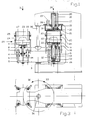
- the molding machine according to the invention has a stand 1 which has a substantially C-shaped cross section in the side view.
- the free ends of the C-shaped stand 1 are connected via a vertical axis 35 which is fixedly mounted on the stand 1 and which carries a turntable unit 3 which can be pivoted about the axis 36.
- the turntable unit 3 has two tables 9, which are each mounted on the top of the turntable unit 3.
- a model plate 22 can be placed on each of the tables 9, which is provided in the usual way with a model 23. As shown in FIG. 1, a molding box 24, which forms a molding cavity 27, can be placed on the model plate 22. A filling frame 25 is usually placed on the molding box 24, which facilitates the filling of the molding sand.
- a lifting and supporting device is arranged on the turntable unit 3 below the table 9.
- This comprises a reciprocating piston 12 which is connected to a piston rod 11, which in turn is attached to the table 9.
- the lifting piston 12 is designed in the form of a double-acting piston and can be moved in a lifting cylinder 10, the lower region of which has a supporting piston 13.
- the supporting piston 13 of the lifting cylinder 10 which is mounted on the rotary table unit 3 and is displaceable relative to it, is first moved downwards until it is in contact with a supporting plate 26 of the stand 1.
- this pressurization causes the reciprocating piston 12 and thus also the table 9 to be moved upward, so that the filling frame 25 is pressed against a compression device which is formed on the upper region of the stand 1.
- the compression device is described in detail below.
- the table 9 In order to prevent the table 9 from rotating, it has at least one table guide rod 14 which can be displaced in a recess in the rotary table unit 3.
- the compression device comprises a press box 15, which is provided with a recess in which a press plate 16 is arranged.
- the recess of the press box 15 is adapted to the size of the filling frame 25 or the molding box 24.
- a press frame 20 can also be arranged on the underside of the press box, as shown in FIG. 1.
- the bottom of the press frame 20 is with provided with a press seal 21, which ensures an airtight seal when the filling frame 25 bears against the press frame 20.
- the press frame 15 is fixedly connected to the stand 1 and has an air inlet 19 through which compressed air can be pressed into the interior 28 of the press box 15 and thus into the mold cavity 27.
- the press plate 16 is connected via a piston rod to a press piston 35 which is movable in a press cylinder 17 and is in the form of a double-acting piston. It is thus possible to lower or raise the press plate.
- a guide rod 18 which is guided displaceably in a recess in the stand or the press box 15.
- the compression device described above thus allows the use of an air flow compression molding process.
- a lifting device is also provided in the area under each table 9, which comprises a lifting cylinder 4, a lifting crossbar 5 connected to this and lifting guide rods 6, which are connected to the lifting crossbar 5.
- a lifting cylinder 4 By actuating the lifting cylinder 4, it is thus possible to lower or raise the lifting crossbeam 5 and thus the guide rods 6.
- a carrier 7 At the upper ends of the guide rods 6, a carrier 7 is releasably attached, on which a lifting pin 8 is mounted. By adjusting the position of the carriers 7, it is possible to adapt the lifting device to the respective shape and configuration of the molding boxes 24 or the filling frames 25.
- the piston connected to the lifting crossbar 5 via the piston rod 34 enables a precisely controllable lifting of the finished form or of the molding box 24 from the model plate 22.
- the pivoting of the turntable unit 3 can be done manually in smaller molding machines, but it is also possible to provide an auxiliary drive for pivoting the turntable unit 3. Furthermore, locking devices can be provided in order to ensure an exact positioning of the tables 9. Since the piston 12 is in the form of a double-acting piston, it is ensured in the position ready for pivoting shown in FIG. 1 that the supporting piston 13 does not bear against the supporting plate 26, so that the rotary table unit 3 can pivot freely.
- molding machine By means of the molding machine according to the invention, it is now possible to lift a filled molding box 24 in the region of a lifting station marked 31 and to replace it with an empty molding box. Furthermore, molding sand can be fed into this lifting station, for example from the operating side 29. While these operations are taking place, it is possible to compress the molding sand accordingly in the area of the compression side 30.
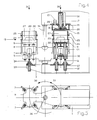
- FIG. 2 shows an end view of the molding machine shown in FIG. 1, but the illustration of the molding box and the filling frame has been omitted.
- FIG. 3 shows a top view of the molding machine according to the invention, which is also not equipped with a molding box or a filling frame.
- the arrows 32 and 33 indicate the pivotability of the turntable unit 3.
- the mold cavity and thus the molding sand located therein is formed by introducing compressed air through the air inlet 19 pre-compressed. Subsequently, a compression is carried out by means of the pressure plate 16. The pressure box cavity 28 is then vented via the air inlet 19, whereupon the pressure plate 16 is withdrawn by the piston 35.
- the second exemplary embodiment differs from the first described exemplary embodiment in that below the filling side and the compaction side the respective lifting and supporting devices are not arranged on the turntable unit but on the frame.
- a number of reciprocating pistons 12 are mounted in cylinders 37 on the compression side on the frame below the turntable unit.
- the lifting pistons 12 each have a coupling at their upper end, which enables a connection to the table guide rods 14, which are mounted on the turntable unit 3 so as to be vertically displaceable.
- the turntable unit 3 has a bearing bush arrangement 38.
- a vertically displaceable piston rod 34 with an associated piston is mounted in a cylinder 39 on the lower part of the frame 1.
- the upper end of the piston rod 34 can be coupled to an extension of a push-off crossbar 5, which in turn has free ends, as shown in particular in FIG. Has carrier 7, which are connected to lifting pins 8.
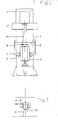
- the piston rod 34 or 11 Since not only a vertical upward movement but also a return movement is to be carried out by means of the piston rod 34 or the reciprocating piston 12, the piston rod 34 or 11 has at its upper end a coupling body 26 which is in the form of a thickened head region is and can be inserted into a groove 39 of the element to be coupled, for example the table guide rod 14.
- the groove 39 extends transversely through the respective element, so that when the turntable unit 3 rotates, the coupling body 26 can be inserted into the groove 39. It is therefore not necessary to take additional clutch measures and / or to manually disengage or engage a clutch.
Landscapes
- Engineering & Computer Science (AREA)
- Mechanical Engineering (AREA)
- Casting Devices For Molds (AREA)
- Casting Or Compression Moulding Of Plastics Or The Like (AREA)
- Presses And Accessory Devices Thereof (AREA)
- Injection Moulding Of Plastics Or The Like (AREA)
- Permanent Magnet Type Synchronous Machine (AREA)
Applications Claiming Priority (2)
| Application Number | Priority Date | Filing Date | Title |
|---|---|---|---|
| DE3830331A DE3830331A1 (de) | 1988-09-07 | 1988-09-07 | Formmaschine |
| DE3830331 | 1988-09-07 |
Publications (3)
| Publication Number | Publication Date |
|---|---|
| EP0357871A2 true EP0357871A2 (fr) | 1990-03-14 |
| EP0357871A3 EP0357871A3 (fr) | 1991-07-31 |
| EP0357871B1 EP0357871B1 (fr) | 1995-03-01 |
Family
ID=6362416
Family Applications (1)
| Application Number | Title | Priority Date | Filing Date |
|---|---|---|---|
| EP89108368A Expired - Lifetime EP0357871B1 (fr) | 1988-09-07 | 1989-05-10 | Machine à mouler |
Country Status (5)
| Country | Link |
|---|---|
| US (1) | US5127816A (fr) |
| EP (1) | EP0357871B1 (fr) |
| AT (1) | ATE119089T1 (fr) |
| DE (3) | DE8817014U1 (fr) |
| ES (1) | ES2072274T3 (fr) |
Cited By (1)
| Publication number | Priority date | Publication date | Assignee | Title |
|---|---|---|---|---|
| WO1995015826A1 (fr) * | 1993-12-11 | 1995-06-15 | Adolf Hottinger Maschinenbau Gmbh | Dispositif de tirage des noyaux ou des moules de fonderie |
Families Citing this family (7)
| Publication number | Priority date | Publication date | Assignee | Title |
|---|---|---|---|---|
| DE4305128A1 (de) * | 1993-02-19 | 1994-08-25 | Wagner Heinrich Sinto Masch | Formmaschine |
| DE4305129A1 (de) * | 1993-02-19 | 1994-08-25 | Wagner Heinrich Sinto Masch | Formmaschine |
| CN101687250A (zh) | 2007-06-01 | 2010-03-31 | 新东工业株式会社 | 附有铸造砂箱的铸型的造型设备及方法 |
| JP5829912B2 (ja) * | 2008-07-21 | 2015-12-09 | ティン ウォング,テック | ホルムアルデヒドを含まない成形品及び関連部品の製造方法 |
| JP5626639B2 (ja) * | 2010-08-09 | 2014-11-19 | 新東工業株式会社 | 鋳型造型方法 |
| CN110842141B (zh) * | 2019-11-29 | 2020-11-17 | 安庆海威尔机械有限公司 | 活塞环砂型成型模具 |
| CN110947919B (zh) * | 2019-12-12 | 2020-11-17 | 安庆海威尔机械有限公司 | 一种脱模机构 |
Family Cites Families (17)
| Publication number | Priority date | Publication date | Assignee | Title |
|---|---|---|---|---|
| DE548756C (de) * | 1930-03-04 | 1932-04-18 | Alfred Baillot | Drehtischformpresse |
| DE820186C (de) * | 1949-08-30 | 1951-11-08 | Badische Maschinenfabrik A G | Formmaschine mit einem in waagerechter Ebene schwenkbaren Drehtisch |
| DE1058701B (de) * | 1955-08-24 | 1959-06-04 | Badische Maschinenfabrik A G S | Vorrichtung zum selbsttaetigen Abheben des Formkastens von der Modellplatte und zum selbsttaetigen Ausfahren des Formkastens bei selbsttaetig arbeitenden Drehtisch-Formmaschinen |
| DE1752932U (de) * | 1957-07-22 | 1957-09-26 | Kabel Vogel & Schemmann Ag | Maschinen zur herstellung von giessereiformen. |
| US3577610A (en) * | 1968-04-16 | 1971-05-04 | Little Inc A | Apparatus for manufacturing prestressed concrete members |
| DE1801314A1 (de) * | 1968-10-04 | 1970-05-06 | Marker Hannes | Spitzenhaltevorrichtung fuer Sicherheits-Skibindungen |
| CH529587A (de) * | 1970-10-22 | 1972-10-31 | Von Roll Ag | Vorrichtung zur Herstellung von Blöcken |
| CH550748A (de) * | 1971-04-28 | 1974-06-28 | Alusuisse | Apparatur zum herstellen von gruenen probekoerpern aus kunstkohle. |
| US3868209A (en) * | 1973-02-22 | 1975-02-25 | Koehring Co | Twin sheet thermoformer |
| IT1010613B (it) * | 1974-04-04 | 1977-01-20 | Longinotti Spa | Dosatore per materiale semi asciut to per la fabbricazione di mat tonelle di cemento a due strati per piastrelle di ceramica ed al tro |
| DE2721874C2 (de) * | 1977-05-14 | 1983-09-29 | Michael 8900 Augsburg Achinger | Gießereiformmaschine |
| US4184533A (en) * | 1978-05-30 | 1980-01-22 | Esco Corporation | Machine for shaping sand into cores or molds |
| JPS5670920A (en) * | 1979-11-14 | 1981-06-13 | Asahi Chem Ind Co Ltd | Apparatus for manufacturing synthetic resin product |
| DE3010652C2 (de) * | 1980-03-20 | 1983-10-20 | Buderus Ag, 6330 Wetzlar | Formanlage zur Herstellung von Gießformen |
| SU1158362A2 (ru) * | 1983-09-14 | 1985-05-30 | Проектно-Технологический Трест Организации И Технологии Шахтного Строительства "Оргтехшахтострой" | Станок дл изготовлени железобетонных зат жек |
| DE3422687C1 (de) * | 1984-06-19 | 1985-06-13 | Adolf Hottinger, Gießerei und Maschinenbau GmbH, 6800 Mannheim | Kern- und Maskenschiessmaschine |
| JPS6268712A (ja) * | 1985-09-20 | 1987-03-28 | Toyoda Gosei Co Ltd | 成形機の型開閉装置 |
-
1988
- 1988-09-07 DE DE8817014U patent/DE8817014U1/de not_active Expired - Lifetime
- 1988-09-07 DE DE3830331A patent/DE3830331A1/de active Granted
-
1989
- 1989-05-10 DE DE58909051T patent/DE58909051D1/de not_active Expired - Fee Related
- 1989-05-10 EP EP89108368A patent/EP0357871B1/fr not_active Expired - Lifetime
- 1989-05-10 ES ES89108368T patent/ES2072274T3/es not_active Expired - Lifetime
- 1989-05-10 AT AT89108368T patent/ATE119089T1/de not_active IP Right Cessation
-
1990
- 1990-07-06 US US07/549,315 patent/US5127816A/en not_active Expired - Lifetime
Cited By (2)
| Publication number | Priority date | Publication date | Assignee | Title |
|---|---|---|---|---|
| WO1995015826A1 (fr) * | 1993-12-11 | 1995-06-15 | Adolf Hottinger Maschinenbau Gmbh | Dispositif de tirage des noyaux ou des moules de fonderie |
| US5701946A (en) * | 1993-12-11 | 1997-12-30 | Adolf Hottinger Maschinenbau Gmbh | Apparatus for shooting foundry cores or molds |
Also Published As
| Publication number | Publication date |
|---|---|
| DE58909051D1 (de) | 1995-04-06 |
| EP0357871B1 (fr) | 1995-03-01 |
| DE8817014U1 (de) | 1991-11-21 |
| US5127816A (en) | 1992-07-07 |
| EP0357871A3 (fr) | 1991-07-31 |
| ES2072274T3 (es) | 1995-07-16 |
| DE3830331C2 (fr) | 1992-07-02 |
| ATE119089T1 (de) | 1995-03-15 |
| DE3830331A1 (de) | 1990-03-08 |
Similar Documents
| Publication | Publication Date | Title |
|---|---|---|
| DE2930874C2 (de) | Formmaschine | |
| DE1265348B (de) | Verfahren und Vorrichtung zum Herstellen von kastenlosen Giessformen | |
| EP4076881A1 (fr) | Dispositif pour la fabrication de blocs de béton | |
| EP0496077B1 (fr) | Dispositif pour la fabrication de pierres | |
| EP0357871B1 (fr) | Machine à mouler | |
| DE2939409A1 (de) | Giessapparat | |
| DE2144388C3 (de) | Preßformmaschine | |
| DE19912829B4 (de) | Anlage zum Herstellen von napfförmigen Betonformkörpern | |
| DE1297818B (de) | Giessereiformmaschine | |
| DE1234940B (de) | Pressformmaschine | |
| DE3622951A1 (de) | Verfahren und formwerkzeug zum herstellen von mit textilen ueberzuegen versehenen polstern aus schaumstoff | |
| EP0327825B1 (fr) | Machine à mouler | |
| DE2344044C2 (de) | Preßvorrichtung zum Formen von Fleisch oder ähnlichen Nahrungsmittelprodukten | |
| DE1241047B (de) | Verfahren und Maschine zum Herstellen von Giessformen | |
| DE19805067B4 (de) | Verfahren zum Herstellen von Betonteilen | |
| CH440568A (de) | Verfahren und Formmaschine zur Herstellung kastenloser Formen | |
| DE1210517B (de) | Verfahren und Vorrichtung zum Loesen einer Giessereiform mit Ballen aus dem Ballenmodell | |
| DE1409550C (de) | Presse zum Herstellen von Hohlziegeln | |
| DD139799B1 (de) | Formmaschine zur herstellung von kastenlosen sandformen | |
| DE2317425C3 (de) | Isostatische Pulverpresse mit mehreren Formteilen | |
| DE1058225B (de) | Drehkreuzformmaschine zur selbsttaetigen Herstellung von Formmasken | |
| DE1577267C3 (de) | Schrottpaketierpresse | |
| CH654765A5 (en) | Core-blowing machine | |
| DE2417198B2 (de) | Vorrichtung zum herstellen kastenloser sandformen | |
| DE1508661B1 (de) | Vorrichtung zum herstellen von kastenlosen giessformen |
Legal Events
| Date | Code | Title | Description |
|---|---|---|---|
| PUAI | Public reference made under article 153(3) epc to a published international application that has entered the european phase |
Free format text: ORIGINAL CODE: 0009012 |
|
| AK | Designated contracting states |
Kind code of ref document: A2 Designated state(s): AT BE CH DE ES FR GB GR IT LI LU NL SE |
|
| PUAL | Search report despatched |
Free format text: ORIGINAL CODE: 0009013 |
|
| AK | Designated contracting states |
Kind code of ref document: A3 Designated state(s): AT BE CH DE ES FR GB GR IT LI LU NL SE |
|
| 17P | Request for examination filed |
Effective date: 19910823 |
|
| 17Q | First examination report despatched |
Effective date: 19920810 |
|
| GRAA | (expected) grant |
Free format text: ORIGINAL CODE: 0009210 |
|
| ITF | It: translation for a ep patent filed | ||
| AK | Designated contracting states |
Kind code of ref document: B1 Designated state(s): AT BE CH DE ES FR GB GR IT LI LU NL SE |
|
| PG25 | Lapsed in a contracting state [announced via postgrant information from national office to epo] |
Ref country code: NL Free format text: LAPSE BECAUSE OF FAILURE TO SUBMIT A TRANSLATION OF THE DESCRIPTION OR TO PAY THE FEE WITHIN THE PRESCRIBED TIME-LIMIT Effective date: 19950301 Ref country code: GR Free format text: LAPSE BECAUSE OF FAILURE TO SUBMIT A TRANSLATION OF THE DESCRIPTION OR TO PAY THE FEE WITHIN THE PRESCRIBED TIME-LIMIT Effective date: 19950301 Ref country code: BE Effective date: 19950301 |
|
| REF | Corresponds to: |
Ref document number: 119089 Country of ref document: AT Date of ref document: 19950315 Kind code of ref document: T |
|
| REF | Corresponds to: |
Ref document number: 58909051 Country of ref document: DE Date of ref document: 19950406 |
|
| GBT | Gb: translation of ep patent filed (gb section 77(6)(a)/1977) |
Effective date: 19950309 |
|
| PG25 | Lapsed in a contracting state [announced via postgrant information from national office to epo] |
Ref country code: LU Free format text: LAPSE BECAUSE OF NON-PAYMENT OF DUE FEES Effective date: 19950531 |
|
| ET | Fr: translation filed | ||
| REG | Reference to a national code |
Ref country code: ES Ref legal event code: FG2A Ref document number: 2072274 Country of ref document: ES Kind code of ref document: T3 |
|
| NLV1 | Nl: lapsed or annulled due to failure to fulfill the requirements of art. 29p and 29m of the patents act | ||
| PLBE | No opposition filed within time limit |
Free format text: ORIGINAL CODE: 0009261 |
|
| STAA | Information on the status of an ep patent application or granted ep patent |
Free format text: STATUS: NO OPPOSITION FILED WITHIN TIME LIMIT |
|
| 26N | No opposition filed | ||
| REG | Reference to a national code |
Ref country code: GB Ref legal event code: IF02 |
|
| PGFP | Annual fee paid to national office [announced via postgrant information from national office to epo] |
Ref country code: FR Payment date: 20020426 Year of fee payment: 14 |
|
| PGFP | Annual fee paid to national office [announced via postgrant information from national office to epo] |
Ref country code: SE Payment date: 20020506 Year of fee payment: 14 |
|
| PGFP | Annual fee paid to national office [announced via postgrant information from national office to epo] |
Ref country code: GB Payment date: 20020508 Year of fee payment: 14 |
|
| PGFP | Annual fee paid to national office [announced via postgrant information from national office to epo] |
Ref country code: AT Payment date: 20020524 Year of fee payment: 14 |
|
| PGFP | Annual fee paid to national office [announced via postgrant information from national office to epo] |
Ref country code: CH Payment date: 20020528 Year of fee payment: 14 |
|
| PGFP | Annual fee paid to national office [announced via postgrant information from national office to epo] |
Ref country code: ES Payment date: 20020529 Year of fee payment: 14 |
|
| PGFP | Annual fee paid to national office [announced via postgrant information from national office to epo] |
Ref country code: DE Payment date: 20020722 Year of fee payment: 14 |
|
| PG25 | Lapsed in a contracting state [announced via postgrant information from national office to epo] |
Ref country code: GB Free format text: LAPSE BECAUSE OF NON-PAYMENT OF DUE FEES Effective date: 20030510 Ref country code: AT Free format text: LAPSE BECAUSE OF NON-PAYMENT OF DUE FEES Effective date: 20030510 |
|
| PG25 | Lapsed in a contracting state [announced via postgrant information from national office to epo] |
Ref country code: SE Free format text: LAPSE BECAUSE OF NON-PAYMENT OF DUE FEES Effective date: 20030511 |
|
| PG25 | Lapsed in a contracting state [announced via postgrant information from national office to epo] |
Ref country code: ES Free format text: LAPSE BECAUSE OF NON-PAYMENT OF DUE FEES Effective date: 20030512 |
|
| PG25 | Lapsed in a contracting state [announced via postgrant information from national office to epo] |
Ref country code: LI Free format text: LAPSE BECAUSE OF NON-PAYMENT OF DUE FEES Effective date: 20030531 Ref country code: CH Free format text: LAPSE BECAUSE OF NON-PAYMENT OF DUE FEES Effective date: 20030531 |
|
| PG25 | Lapsed in a contracting state [announced via postgrant information from national office to epo] |
Ref country code: DE Free format text: LAPSE BECAUSE OF NON-PAYMENT OF DUE FEES Effective date: 20031202 |
|
| GBPC | Gb: european patent ceased through non-payment of renewal fee |
Effective date: 20030510 |
|
| EUG | Se: european patent has lapsed | ||
| REG | Reference to a national code |
Ref country code: CH Ref legal event code: PL |
|
| PG25 | Lapsed in a contracting state [announced via postgrant information from national office to epo] |
Ref country code: FR Free format text: LAPSE BECAUSE OF NON-PAYMENT OF DUE FEES Effective date: 20040130 |
|
| REG | Reference to a national code |
Ref country code: FR Ref legal event code: ST |
|
| REG | Reference to a national code |
Ref country code: ES Ref legal event code: FD2A Effective date: 20030512 |
|
| PG25 | Lapsed in a contracting state [announced via postgrant information from national office to epo] |
Ref country code: IT Free format text: LAPSE BECAUSE OF NON-PAYMENT OF DUE FEES;WARNING: LAPSES OF ITALIAN PATENTS WITH EFFECTIVE DATE BEFORE 2007 MAY HAVE OCCURRED AT ANY TIME BEFORE 2007. THE CORRECT EFFECTIVE DATE MAY BE DIFFERENT FROM THE ONE RECORDED. Effective date: 20050510 |