EP0358065A2 - Agencement pour avancer le traitement des tabloids - Google Patents
Agencement pour avancer le traitement des tabloids Download PDFInfo
- Publication number
- EP0358065A2 EP0358065A2 EP89115750A EP89115750A EP0358065A2 EP 0358065 A2 EP0358065 A2 EP 0358065A2 EP 89115750 A EP89115750 A EP 89115750A EP 89115750 A EP89115750 A EP 89115750A EP 0358065 A2 EP0358065 A2 EP 0358065A2
- Authority
- EP
- European Patent Office
- Prior art keywords
- products
- cluster
- conveyor
- printed products
- tabloids
- Prior art date
- Legal status (The legal status is an assumption and is not a legal conclusion. Google has not performed a legal analysis and makes no representation as to the accuracy of the status listed.)
- Granted
Links
- 238000012545 processing Methods 0.000 title claims abstract description 80
- 238000000034 method Methods 0.000 claims abstract description 48
- 238000006243 chemical reaction Methods 0.000 claims abstract description 20
- 238000010079 rubber tapping Methods 0.000 claims abstract description 8
- 230000008569 process Effects 0.000 claims description 19
- 238000007639 printing Methods 0.000 claims description 11
- 238000012546 transfer Methods 0.000 claims description 11
- 238000009966 trimming Methods 0.000 claims description 3
- 238000011144 upstream manufacturing Methods 0.000 claims description 2
- 239000000047 product Substances 0.000 description 110
- 239000007795 chemical reaction product Substances 0.000 description 12
- 238000007645 offset printing Methods 0.000 description 5
- WYWHKKSPHMUBEB-UHFFFAOYSA-N 6-Mercaptoguanine Natural products N1C(N)=NC(=S)C2=C1N=CN2 WYWHKKSPHMUBEB-UHFFFAOYSA-N 0.000 description 3
- 230000003139 buffering effect Effects 0.000 description 3
- 229940095374 tabloid Drugs 0.000 description 3
- 230000008901 benefit Effects 0.000 description 2
- 230000008859 change Effects 0.000 description 2
- 238000005516 engineering process Methods 0.000 description 2
- 238000004519 manufacturing process Methods 0.000 description 2
- 230000002411 adverse Effects 0.000 description 1
- 230000004888 barrier function Effects 0.000 description 1
- 230000015572 biosynthetic process Effects 0.000 description 1
- 239000000969 carrier Substances 0.000 description 1
- 230000001419 dependent effect Effects 0.000 description 1
- 238000013461 design Methods 0.000 description 1
- 238000007646 gravure printing Methods 0.000 description 1
- 238000003780 insertion Methods 0.000 description 1
- 230000037431 insertion Effects 0.000 description 1
- REQCZEXYDRLIBE-UHFFFAOYSA-N procainamide Chemical compound CCN(CC)CCNC(=O)C1=CC=C(N)C=C1 REQCZEXYDRLIBE-UHFFFAOYSA-N 0.000 description 1
- 230000000717 retained effect Effects 0.000 description 1
- 238000000926 separation method Methods 0.000 description 1
- 238000004804 winding Methods 0.000 description 1
Images




Classifications
-
- B—PERFORMING OPERATIONS; TRANSPORTING
- B65—CONVEYING; PACKING; STORING; HANDLING THIN OR FILAMENTARY MATERIAL
- B65H—HANDLING THIN OR FILAMENTARY MATERIAL, e.g. SHEETS, WEBS, CABLES
- B65H29/00—Delivering or advancing articles from machines; Advancing articles to or into piles
- B65H29/003—Delivering or advancing articles from machines; Advancing articles to or into piles by grippers
- B65H29/005—Delivering or advancing articles from machines; Advancing articles to or into piles by grippers by chains or bands having mechanical grippers engaging the side edges of articles, e.g. newspaper conveyors
-
- B—PERFORMING OPERATIONS; TRANSPORTING
- B42—BOOKBINDING; ALBUMS; FILES; SPECIAL PRINTED MATTER
- B42C—BOOKBINDING
- B42C1/00—Collating or gathering sheets combined with processes for permanently attaching together sheets or signatures or for interposing inserts
- B42C1/12—Machines for both collating or gathering and permanently attaching together the sheets or signatures
-
- B—PERFORMING OPERATIONS; TRANSPORTING
- B42—BOOKBINDING; ALBUMS; FILES; SPECIAL PRINTED MATTER
- B42C—BOOKBINDING
- B42C19/00—Multi-step processes for making books
- B42C19/08—Conveying between operating stations in machines
-
- B—PERFORMING OPERATIONS; TRANSPORTING
- B65—CONVEYING; PACKING; STORING; HANDLING THIN OR FILAMENTARY MATERIAL
- B65H—HANDLING THIN OR FILAMENTARY MATERIAL, e.g. SHEETS, WEBS, CABLES
- B65H2301/00—Handling processes for sheets or webs
- B65H2301/40—Type of handling process
- B65H2301/44—Moving, forwarding, guiding material
- B65H2301/447—Moving, forwarding, guiding material transferring material between transport devices
- B65H2301/4471—Grippers, e.g. moved in paths enclosing an area
- B65H2301/44712—Grippers, e.g. moved in paths enclosing an area carried by chains or bands
-
- B—PERFORMING OPERATIONS; TRANSPORTING
- B65—CONVEYING; PACKING; STORING; HANDLING THIN OR FILAMENTARY MATERIAL
- B65H—HANDLING THIN OR FILAMENTARY MATERIAL, e.g. SHEETS, WEBS, CABLES
- B65H2301/00—Handling processes for sheets or webs
- B65H2301/40—Type of handling process
- B65H2301/44—Moving, forwarding, guiding material
- B65H2301/447—Moving, forwarding, guiding material transferring material between transport devices
- B65H2301/4478—Transport device acting on edge of material
Definitions
- the invention lies in the field of printing technology and relates to a method and an arrangement according to the preamble of patent claims 1 and 14, respectively.
- the print products produced by the rotary press are often converted into the form of tabloids, i.e. single or several printed sheets folded once, transferred and thus fed to further work steps.
- the systems set up for such processing processes are therefore specially adapted to these processing formats.
- end product is to be understood here to mean printed products as they exist after the method according to the invention has been carried out, ie at the exit of a processing system, a forwarding state generally being reached at this exit.
- starting product is to be understood to mean all printed products as they are fed to a device according to the invention, in order then to be converted into end products. ie generally tabloids. It goes without saying that, for example, two-folds or, if need be, also multiple folds can be supplied as starting products. However, it must then generally be accepted that the deformations mentioned at the beginning of the collar or the second fold already occur.
- end products as the term is understood here, can also be added to further work steps.
- tabloids are fed in by a conventional rotation at a certain speed v, this means that they basically have to be further processed at the same speed v.
- the desired end products generally have a relatively large volume of, for example, 300 pages. This further processing, especially in the case of such extensive end products, sometimes requires relatively slow work steps, so that the required processing capacity cannot be achieved by a long way.
- Complex measures make it possible to increase the capacity within certain limits, for example by providing buffering after the rotation or by dividing the product stream into several individual streams. However, these measures require a relatively large amount of effort and lead to extensive adjustments to the overall system.
- the large processing capacity makes it possible to fold the tabloids into smaller formats only in the course of the last working steps, especially after the tabloids have been cut open, and to economically produce small-format print product formats in offset printing. It must be noted that the method according to the invention solves the problem of very different processing capacities of the individual system components at the same time.
- the basic sequence of the method according to the invention is shown in FIG. It must be emphasized that for the sake of clarity, essential elements of the invention have been left out of this overview.
- the process within and immediately after the printing press is not shown in detail here, but it is assumed that starting products 8, here tabloids, are conveyed with funding or in a conveyor system 1 with a specific cycle T.
- the starting products 8 can in particular be converted into the formats of the end products 9 mentioned in the figure using the method according to the invention. These formats are made possible by the method of cutting open 11, stapling 12, folding 13 and 2 or 3-sided trimming 14, 15.
- An essential element of the method is also the conveyor conversion 10, which will be discussed in more detail with reference to FIG. 2.
- the starting products are fed continuously, preferably clocked, via a conveyor device, here a cycle conveyor 21, to a conveyor conversion device 20.
- This conversion device 20 is used to convert the starting products, which are serially fed here in a conventional manner, into printed product clusters.
- a print product clunster is to be understood here to mean a group of at least two individual print products which are processed in parallel in at least a partial route or a partial process. It should be emphasized that parallel processing is understood to mean functional parallelism , ie the individual printed products of such a cluster are simultaneously subject to identical or functionally related work steps. The mutual arrangement of the printed products of a cluster can vary.
- the printed products are preferably arranged next to one another and parallel to one another in one plane.
- the processing of the printed products of each cluster is thus carried out depending on the work cycle T '. This is in contrast to the division of a conveyor line into two or more parallel lines in printing plant conveyor technology, which may have a geometric parallel guidance, but which alone have the function of reducing the conveyor speed of the feed line.
- the simultaneous processing of a cluster is no consideration that a functionally related unit of printed products.
- This further processing is also to be distinguished from processes which combine several printed products, for example an insertion process, in order to subsequently promote or process them together as a unit work.
- each individual printed product is processed in parallel in a cluster, but each starting product is processed "on its own", nota bene in each case in a functionally dependent manner together with the other printed products of the cluster .
- the function of this conveying conversion device can also be understood as the conversion of, for example, a clocked and serially conveyed scale stream into a cluster stream, which is conveyed at most with a changed clock.
- the work steps described above are applied simultaneously to the entire cluster, ie the products contained in a cluster are processed in parallel.
- Conventional workstations can be used to carry out the individual work steps, with the only requirement that they can process the printed products of an entire cluster at the same time.
- the size of a cluster can vary depending on the application. The size of a cluster is preferably also selected as a function of the cycle or conveying speed T ′ desired for cluster processing.
- the cycle T ' can be increased or the conveying speed of the printed product clusters can be reduced, so that the subsequent steps can be carried out at the required speed. It is a great advantage of the method according to the invention that the individual work steps, depending on the size of the clusters, can take place relatively slowly. This makes it possible, even in very fast overall processes, inexpensive, slow-moving inputs to use individual components. In addition, interface problems that arise due to different processing speeds of the individual components are largely avoided. As can be seen from FIG.
- the starting products, after they have been converted into a cluster of 4 are cut by a device 22 for cutting the tabloids, then by an envelope feeder 23, a stapling device 24, a folding device 25 and finally by a side trimming device 26 out.
- the respective work steps can take place in any sequence or can also be suppressed or omitted, so that depending on the function selected, different types of end products are available at the exit 27 for parceling and forwarding.
- further functions can be provided or the end products can also be fed to a further conveyor device, which allow a subsequent, remote processing process.
- FIG. 3 now shows a schematic representation of an embodiment of the device according to the invention.
- a buffer as it emerges from the CH patent application 580 / 88-6, or an investor, output products are fed via a conveyor 1 to two processing systems 30 ', 30'.
- the device is explained on the basis of a system with a clocked feed, the printed products can of course be transported continuously in an analogous manner by means of other conveying means and only gripped individually for conversion into printed product clusters and converted into clocked processing.
- the conveying cycle of the printed products is denoted by T.
- the printed products are each fed to a conveyor conversion device 20 ', 20 ⁇ .
- printed products are removed from a linear feed at two different locations per printing product, for example by picking out individual starting products with a gripping device.
- the feed can also be divided into two conveyor sections in a conventional manner by means of a switch, the latter each supplying a conversion device 20 ′, 20 ⁇ .
- the individual printed product clusters 2, indicated here with four printed products, for example, are shown in their various transport or processing positions.
- the individual processing options are not specifically emphasized here and reference can be made to FIG. 2 in this regard.
- further sub-products can also be supplied, possibly via additional feeds, and merged with the printed products of the clusters in any manner, for example by inserting them. It is therefore possible to combine entire print product clusters, ie several print products at the same time, which leads to very high work capacities.
- the clusters are inside the processing systems 30 ', 30 ⁇ transported and / or processed with a cycle T' or T ⁇ . In many cases the clocks T 'and T ⁇ will be the same size. On the other hand, if the processing systems 30 'and 30 30 do not carry out identical work steps, for example, it may be desirable to promote the clusters within the two systems with a different cycle.
- devices 31', 31 ⁇ for converting the clusters may be present.
- a new serial promotion is possible in a simple manner.
- the cluster-wise processing of the printed products with a cycle T ′ or T ⁇ enables, for example, a simple return to the original cycle T.
- a processing system 30, which requires relatively slow work steps, such as stapling extensive printed products, can be easily integrated into an overall process will.
- the method according to the invention is particularly suitable in an overall system with a system clock T. It is then easily possible to link the cluster clock T ′ or T ⁇ with the system clock T.
- a central control then makes it possible, for example, to control the conveyor conversion devices in a simple manner and to convert the serial to parallel, group-wise processing, or to convert the clusters back into serial conveying or serial processing with isolated print products or a stream of shingles . For example, it is also easily possible to carry out buffering in this way.
- FIG. 4a now shows the conversion of starting products serially conveyed by means of a clock conveyor into clusters of three printed products each.
- every third copy is taken from three different removal points 19 ', 19 ⁇ , 19 ′′′.
- three starting products are taken from each of these tapping points and conveyed or processed next to each other as a common cluster.
- the individual printed products are shaded differently for the sake of clarity, the initial products fed in this way are identical products.
- the removed printed products are preferably arranged next to one another and parallel to one another within a cluster. Using conventional switches, it is easily possible to combine the printed products combined in the individual tapping points into clusters on a common conveyor line in order to obtain a single cluster stream.
- FIG. 4b shows a further example of a conveyor conversion device which converts the serial scale stream 3 into clusters to four starting products.
- every second and a total of four printed products are removed at a first removal point 19 '.
- At the second removal point 19 ⁇ is the same removal process.
- the individual starting products are removed at the removal points, for example, using a gripping device according to CH patent application 01 756 / 86-8 or a device according to the CH patent applications of the same applicant dated October 23, 1987 and August 28, 1987 [application numbers not yet known].
- a gripping device according to CH patent application 01 756 / 86-8 or a device according to the CH patent applications of the same applicant dated October 23, 1987 and August 28, 1987 [application numbers not yet known].
- an entire cluster is either put together simultaneously with four grippers at the respective tapping point, or four starting products are removed in succession with a single gripper.
- the processing systems 30 ', 30 ⁇ or their funding 36-46, 50, 51 are preferably arranged transversely to the conveyor system 1, so that a plurality of processing systems or conveyor conversion devices 20', 20 ⁇ are arranged side by side can. Although a mutually perpendicular arrangement of the processing systems and the conveyor system 1 is usually preferable, the conveying means 36-46, 50, 51 can run at any angle to the conveyor system 1.
- the transport of the clusters in this exemplary embodiment runs on at least one section 32 ′, 32 ⁇ at right angles to the original transport direction after the conversion devices 20 ′, 20 ⁇ .
- Such a deflection of the direction of transport Cluster is required, for example, if this is necessary due to the accessibility of a processing device.
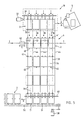
- FIG. 5 now shows schematically an exemplary embodiment for the conveyance of printed product clusters 2 with four printed products.
- the printed products fed to the latter are separated by means of a feeder 5, which is shown only schematically in this figure. It must be noted that investor 5 has been shown in a greatly reduced form for the sake of clarity.
- the printed products are fed to it via a conveyor, not shown here, for example a clamp conveyor.
- Such a feeder 5 and the type of separation can be configured in a conventional manner.
- the printed products separated in this way are then conveyed in the direction of arrow A to a removal point 19 by means of a conveying means 1, for example also a clamp conveyor.
- the clusters 2, which are assembled by means of the removal station 19 are fed to the workstations downstream of the removal station by means of a plurality of chain strands 36, the latter being indicated here by dash-dotted lines.
- a common drive shaft 39 is driven by a first motor 37.
- the circulating chain strands 36 are guided over deflection wheels of the drive shaft and a second shaft 40.
- the drive of these chain strands 36 is not continuous, but with a cycle T '.
- Conveying cams 41 are arranged on the chain strands 36 at regular intervals (only two of these conveying cams 41 are designated in the figure).
- eight such chain strands 36 are provided here to promote a cluster with four printed products each. Each individual printed product is transported in the direction of arrows B by two feed cams 41. Since the chain strands 36 in this Embodiment are driven together, the printed products are necessarily transported synchronously.
- the printed products are preferably on conveyor plates, which can be designed in a conventional manner.
- the conveying cams 41 ensure the parallel alignment of the printed products in the transport direction.
- a lifting cylinder 42 By means of a lifting cylinder 42, vertical guide plates 43 are moved back and forth transversely to the transport direction in the direction of arrow C.
- the individual printed products of a cluster are pushed against guide rails or plates 44 and thus correctly positioned laterally.
- counter cams 45 are provided at the individual work stations for positioning the clusters in the transport direction. The timed promotion and processing of the clusters enables the individual print products of a cluster to be fine-tuned at the individual workstations.
- the deflection by 90 ° is achieved by transfer to a rotating gripper chain 50, for example a grip chain according to DE patent 2151583.
- a rotating gripper chain 50 for example a grip chain according to DE patent 2151583.
- eight grippers 51 two for each printed product, the printed products of a cluster are gripped synchronously.
- This gripper chain 50 is driven by a second motor 38.
- the clusters are transported further in the direction of arrow D by means of this gripper chain.
- FIGS. 6a and 6b illustrate the transfer of the clusters from the transport chain strands 36 to the gripper chain 50.
- a conveyor chain 36 with an associated deflection wheel 46 can be seen on the shaft 40.
- a single conveyor cam 41, 41 ' is shown in two positions.
- the conveyor cam is in position 41 during transport.
- By means of a control link the cam is pivoted during the transfer into the transfer position 41 '.
- the gripper chain is preferably guided over a chain guide 53 in the area of the transfer point.
- the grippers 51 of the gripper chain 50 are in an open standby position for taking over a cluster in each case. As soon as a cluster engages in the corresponding gripper 51, a locking device is actuated.
- the grippers 51 preferably have stops 54, against which the printed products are brought into abutment during the transfer. As can be seen from the drawing, the grippers 51 have a certain spring travel in the direction of the arrow E, so that small linear movements of the clusters in the transport direction can be absorbed during the transfer.
- Figure 6b shows two grippers 51 and the stops 54 with a gripped printed product in a view from above. The direction of conveyance is shown by arrow D.
- the transfer of the printed products 4 is preferably monitored and controlled by a photo cell.
- FIGS. 7a to 7c show the positioning of the printed products at a work station in different stages.
- the positioning device 49 has at least one counter-cam 45 and / or a pre-positioning cam 47.
- Pre-positioning cams and counter-cams basically perform the same task and are generally of the same design.
- the opposing cam of a work station can also take over the function of the pre-positioning cams of the subsequent work station or be identical to them.
- FIG. 7b shows two printed products 4, which are on the one hand on the counter cam 45, on the other hand on the prepositioning cam 47 in the stop.
- the printed products are aligned before they are brought into the actual workstation, which allows fast cycle cycles in clocked operation.
- These two print products are thus correctly positioned or prepositioned in the transport direction for processing.
- the printed product 4 'already processed in this work station which can perform any function such as, for example, slicing, is conveyed to the left into a further work station.
- FIG. 7c shows the printed products in the transport phase.
- a guide rail 44 can be seen, which serves the printed products 4, 4 'as a guide.
- FIG. 8 shows a section through the positioning device 49 transverse to the conveying direction to illustrate this lateral alignment.
- a cluster with printed products 4 is transported forward perpendicular to the plane of the drawing and is brought into abutment with one counter cam 45 each.
- a lifting cylinder 42 By means of a lifting cylinder 42, four guide plates 43 coupled by one or more carriers 34 can be moved back and forth transversely to the conveying direction in the direction of arrow C for the purpose of the lateral direction of the printed products 4.
- the printed products 4 are pushed against the guide rails 44 and are then exactly aligned for processing both in the transport direction and transversely thereto.
- FIG. 9 shows a further exemplary embodiment for the actuation of the counter-cams 45.
- the counter-cam By means of an eccentric 57, the counter-cam is moved into the positioning or conveying position depending on the conveying cycle brought.
- the counter cam 45 is at the top, ie in the positioning position, and is used to align a printed product 4 in the transport direction B.
- the invention is preferably used in the field of offset printing, but can also be used for gravure printing processes or other printing processes.
- a further embodiment of the invention provides that the conveyor conversion devices take over the starting products from several investors and combine them into clusters.
- the conveyor conversion devices take over the starting products from several investors and combine them into clusters.
- clusters can also be composed of starting products from two or more rotary presses or winding stations.
- this removal device has a number of gripping devices corresponding to the number of conveyor systems (1), so that a starting product can be removed from each conveyor system at the same time, which are then combined into a cluster.
- Drag chain drives and, in particular, an articulated chain, as described in Swiss Patent 538,965 are generally suitable for clocked feeding of the clusters into the individual work stations.
- the processing of the clusters can also be clocked, i.e. done continuously in the run.
Landscapes
- Mechanical Engineering (AREA)
- Engineering & Computer Science (AREA)
- Discharge By Other Means (AREA)
- Soil Working Implements (AREA)
- Separation, Sorting, Adjustment, Or Bending Of Sheets To Be Conveyed (AREA)
- Electrical Discharge Machining, Electrochemical Machining, And Combined Machining (AREA)
- Harvester Elements (AREA)
- Threshing Machine Elements (AREA)
- Auxiliary Devices For Music (AREA)
- Saccharide Compounds (AREA)
- Paper (AREA)
- Drying Of Semiconductors (AREA)
- Structure Of Transmissions (AREA)
Priority Applications (1)
| Application Number | Priority Date | Filing Date | Title |
|---|---|---|---|
| AT89115750T ATE98604T1 (de) | 1988-09-09 | 1989-08-26 | Anordnung zur tabloid-weiterverarbeitung. |
Applications Claiming Priority (2)
| Application Number | Priority Date | Filing Date | Title |
|---|---|---|---|
| CH338288 | 1988-09-09 | ||
| CH3382/88 | 1988-09-09 |
Publications (3)
| Publication Number | Publication Date |
|---|---|
| EP0358065A2 true EP0358065A2 (fr) | 1990-03-14 |
| EP0358065A3 EP0358065A3 (en) | 1990-08-29 |
| EP0358065B1 EP0358065B1 (fr) | 1993-12-15 |
Family
ID=4254751
Family Applications (1)
| Application Number | Title | Priority Date | Filing Date |
|---|---|---|---|
| EP89115750A Expired - Lifetime EP0358065B1 (fr) | 1988-09-09 | 1989-08-26 | Agencement pour avancer le traitement des tabloids |
Country Status (8)
| Country | Link |
|---|---|
| US (1) | US5067697A (fr) |
| EP (1) | EP0358065B1 (fr) |
| JP (1) | JP2857425B2 (fr) |
| AT (1) | ATE98604T1 (fr) |
| AU (1) | AU626314B2 (fr) |
| CA (1) | CA1324158C (fr) |
| DE (1) | DE58906425D1 (fr) |
| FI (1) | FI98450C (fr) |
Cited By (2)
| Publication number | Priority date | Publication date | Assignee | Title |
|---|---|---|---|---|
| DE4223524A1 (de) * | 1992-07-17 | 1994-01-20 | Roland Man Druckmasch | Falzapparat |
| WO2011109916A1 (fr) * | 2010-03-11 | 2011-09-15 | Ferag Ag | Dispositif de commande et procédé pour réguler la vitesse d'un convoyeur |
Families Citing this family (8)
| Publication number | Priority date | Publication date | Assignee | Title |
|---|---|---|---|---|
| CH687872A5 (de) * | 1994-08-17 | 1997-03-14 | Ferag Ag | Verfahren zur kontinuierlichen Herstellung von verschiedenartigen Druckprodukten aus verschiedenen, bedruckten Druckprodukteteilen. |
| US5499803A (en) * | 1994-11-23 | 1996-03-19 | Am International, Inc. | Collator without a main line drive shaft |
| DE59705036D1 (de) * | 1996-06-19 | 2001-11-29 | Ferag Ag | Verfahren zur Herstellung von mehrblättrigen Druckprodukten die aus gefalzten Bogen bestehen |
| CZ298144B6 (cs) * | 1997-11-27 | 2007-07-04 | Lonza Ag | Zpusob výroby (1S,4R)- nebo (1R,4S)-4-(2-amino-6-chlor-9-H-purin-9-yl)-2-cyklopenten-1-methanolu |
| US7588239B2 (en) * | 2005-12-14 | 2009-09-15 | Pitney Bowes Inc. | Transport and alignment system |
| EP2200828A4 (fr) * | 2007-10-26 | 2012-04-04 | Goss Int Americas Inc | Presse sectionnée d'impression de tabloïdes et méthode associée |
| US7857297B2 (en) * | 2007-11-30 | 2010-12-28 | Pitney Bowes Inc. | Electrodynamic propulsion system for conveying sheet material |
| US8388299B2 (en) * | 2008-04-18 | 2013-03-05 | R. R. Donnelley & Sons Company | Systems and methods to produce and sequence a plurality of different books |
Family Cites Families (17)
| Publication number | Priority date | Publication date | Assignee | Title |
|---|---|---|---|---|
| FR1012155A (fr) * | 1949-06-20 | 1952-07-07 | Manuf De Machines Modernes | Machine automatique pour la production de blocs imprimés tels que les blocs ou calendriers éphémérides |
| CH584153A5 (fr) * | 1973-10-10 | 1977-01-31 | Ferag Ag | |
| US3982453A (en) * | 1974-07-15 | 1976-09-28 | American Bank Note Company | Method of assembling numbered documents in order |
| US4179107A (en) * | 1975-10-20 | 1979-12-18 | Amprint Corp. | Printing and collating method |
| DE2741332A1 (de) * | 1977-09-14 | 1979-03-22 | Mohn Gmbh Reinhard | Verfahren zur herstellung eines buchblocks sowie vorrichtung zur durchfuehrung des verfahrens |
| CH637091A5 (de) * | 1979-01-29 | 1983-07-15 | Ferag Ag | Vorrichtung zum zufuehren von in einem schuppenstrom anfallenden flaechigen erzeugnissen, insbesondere druckprodukten, zu einem transporteur. |
| DE3018987C2 (de) * | 1980-05-17 | 1983-10-27 | Bielomatik Leuze Gmbh + Co, 7442 Neuffen | Vorrichtung zur Herstellung von Blattstapeln |
| AU544938B2 (en) * | 1981-08-10 | 1985-06-20 | De La Rue Giori S.A. | Processing sheet piles |
| CH663750A5 (de) * | 1982-04-08 | 1988-01-15 | De La Rue Giori Sa | Verfahren und vorrichtung zur herstellung druckfrischer, numerierter und auf format geschnittener wertscheine. |
| SE8206468L (sv) * | 1982-11-12 | 1984-05-13 | Wamac Ab | Anordning for sammankorning av tva eller flera tidningsstrommar |
| GB8318465D0 (en) * | 1983-07-07 | 1983-08-10 | Drg Uk Ltd | Book making apparatus |
| US4585220A (en) * | 1983-08-23 | 1986-04-29 | Bell & Howell Company | Method of operating insertion machine and printer with control signals stored on searchable medium |
| JPS60159119A (ja) * | 1984-01-30 | 1985-08-20 | Toyota Motor Corp | 等速ジヨイント外筒の製造方法 |
| US4519599A (en) * | 1984-05-11 | 1985-05-28 | R. R. Donnelley & Sons Company | Method and apparatus for tandem stitching of books in a bindery line |
| CH670619A5 (fr) * | 1986-04-29 | 1989-06-30 | Sft Ag Spontanfoerdertechnik | |
| DE3883019D1 (de) * | 1987-02-11 | 1993-09-16 | Ferag Ag | Einrichtung zum sammeln von gefalteten druckbogen. |
| US4795143A (en) * | 1987-07-21 | 1989-01-03 | Tsai Chein M | Circulating multi-forming continuous printing machine |
-
1989
- 1989-08-16 AU AU39971/89A patent/AU626314B2/en not_active Ceased
- 1989-08-17 US US07/394,879 patent/US5067697A/en not_active Expired - Lifetime
- 1989-08-24 CA CA000609274A patent/CA1324158C/fr not_active Expired - Fee Related
- 1989-08-26 EP EP89115750A patent/EP0358065B1/fr not_active Expired - Lifetime
- 1989-08-26 DE DE89115750T patent/DE58906425D1/de not_active Expired - Lifetime
- 1989-08-26 AT AT89115750T patent/ATE98604T1/de not_active IP Right Cessation
- 1989-09-01 FI FI894118A patent/FI98450C/fi not_active IP Right Cessation
- 1989-09-08 JP JP1234525A patent/JP2857425B2/ja not_active Expired - Lifetime
Cited By (4)
| Publication number | Priority date | Publication date | Assignee | Title |
|---|---|---|---|---|
| DE4223524A1 (de) * | 1992-07-17 | 1994-01-20 | Roland Man Druckmasch | Falzapparat |
| US5437442A (en) * | 1992-07-17 | 1995-08-01 | Man Roland Druckmaschinen Ag | Single or plural sheet folding apparatus for use with rotary printing presses |
| WO2011109916A1 (fr) * | 2010-03-11 | 2011-09-15 | Ferag Ag | Dispositif de commande et procédé pour réguler la vitesse d'un convoyeur |
| US9008834B2 (en) | 2010-03-11 | 2015-04-14 | Ferag Ag | Control device and method for controlling the speed of a conveyor |
Also Published As
| Publication number | Publication date |
|---|---|
| ATE98604T1 (de) | 1994-01-15 |
| JPH02261762A (ja) | 1990-10-24 |
| AU3997189A (en) | 1990-03-15 |
| FI894118A0 (fi) | 1989-09-01 |
| EP0358065B1 (fr) | 1993-12-15 |
| EP0358065A3 (en) | 1990-08-29 |
| FI98450B (fi) | 1997-03-14 |
| FI894118A7 (fi) | 1990-03-10 |
| JP2857425B2 (ja) | 1999-02-17 |
| CA1324158C (fr) | 1993-11-09 |
| AU626314B2 (en) | 1992-07-30 |
| DE58906425D1 (de) | 1994-01-27 |
| US5067697A (en) | 1991-11-26 |
| FI98450C (fi) | 1997-06-25 |
Similar Documents
| Publication | Publication Date | Title |
|---|---|---|
| EP0911291B1 (fr) | Dispositif de pliage dans une machine plieuse à grande vitesse | |
| EP1209000B1 (fr) | Méthode et dispositif pour fabriquer un journal | |
| EP0257390A1 (fr) | Appareil à plier | |
| EP2263956A1 (fr) | Dispositif de transport pour le transport de produits d'impression et installation dotée d'un tel dispositif de transport | |
| EP0358065B1 (fr) | Agencement pour avancer le traitement des tabloids | |
| EP0342490A2 (fr) | Machine à plier | |
| EP0250758A1 (fr) | Dispositif de pliage et de convoyage | |
| EP0344102A2 (fr) | Dispositif d'assemblage de produits imprimés | |
| DE2911350A1 (de) | Vorrichtung zum aufteilen eines kontinuierlichen stromes, insbesondere eines schuppenstromes, von flaechigen erzeugnissen in einzelne gruppen | |
| EP0358066B1 (fr) | Procédé et disposition pour la transformation de produits imprimés | |
| EP1055626B1 (fr) | Méthode et dispositif pour dévier des feuilles imprimées | |
| DE3427570C2 (fr) | ||
| EP0482399B1 (fr) | Dispositif pour ouvrir et délivrer en position ouverte des produits pliés | |
| EP1222132B1 (fr) | Procede et dispositif pour la formation de groupes de feuilles a partir de plusieurs feuilles | |
| EP2452904B1 (fr) | Dispositif de transport de piles de documents, notamment de documents de sécurité, vers des stations de reliure | |
| DE102020108483A1 (de) | Buchfertigungsstrasse und Verfahren sowohl zur Herstellung von Einzelbüchern als auch von Kleinst- oder Kleinauflagen von Büchern | |
| DE2729222A1 (de) | Vorrichtung zum umwenden und ansammeln einer vorgegebenen anzahl von buechern | |
| EP1312568B1 (fr) | Assembleuse pour former des livres non reliés | |
| WO2001014234A1 (fr) | Procede et dispositif pour receptionner au moins deux feuilles placees a la maniere d'ecailles dans une machine de manipulation de feuilles | |
| EP0976673B1 (fr) | Dispositif d'alimentation pour produits plats | |
| DE102007002090B4 (de) | Verfahren und Vorrichtung zum Nähen von Dokumenten | |
| EP1954615B1 (fr) | Procédé et dispositif pour le traitement au choix de produits imprimés | |
| DE1761377A1 (de) | Papierbogenfalzmaschine | |
| DE10131777A1 (de) | Verfahren und Vorrichtung zur Herstellung von Druckerzeugnissen | |
| DE3312931A1 (de) | Verfahren zur herstellung von wenigstens sechzehn seiten aufweisenden broschueren aus einem bogen |
Legal Events
| Date | Code | Title | Description |
|---|---|---|---|
| PUAI | Public reference made under article 153(3) epc to a published international application that has entered the european phase |
Free format text: ORIGINAL CODE: 0009012 |
|
| AK | Designated contracting states |
Kind code of ref document: A2 Designated state(s): AT CH DE FR GB IT LI SE |
|
| PUAL | Search report despatched |
Free format text: ORIGINAL CODE: 0009013 |
|
| AK | Designated contracting states |
Kind code of ref document: A3 Designated state(s): AT CH DE FR GB IT LI SE |
|
| 17P | Request for examination filed |
Effective date: 19901213 |
|
| 17Q | First examination report despatched |
Effective date: 19920821 |
|
| ITF | It: translation for a ep patent filed | ||
| GRAA | (expected) grant |
Free format text: ORIGINAL CODE: 0009210 |
|
| AK | Designated contracting states |
Kind code of ref document: B1 Designated state(s): AT CH DE FR GB IT LI SE |
|
| REF | Corresponds to: |
Ref document number: 98604 Country of ref document: AT Date of ref document: 19940115 Kind code of ref document: T |
|
| GBT | Gb: translation of ep patent filed (gb section 77(6)(a)/1977) |
Effective date: 19931220 |
|
| REF | Corresponds to: |
Ref document number: 58906425 Country of ref document: DE Date of ref document: 19940127 |
|
| ET | Fr: translation filed | ||
| PLBE | No opposition filed within time limit |
Free format text: ORIGINAL CODE: 0009261 |
|
| STAA | Information on the status of an ep patent application or granted ep patent |
Free format text: STATUS: NO OPPOSITION FILED WITHIN TIME LIMIT |
|
| 26N | No opposition filed | ||
| EAL | Se: european patent in force in sweden |
Ref document number: 89115750.5 |
|
| PGFP | Annual fee paid to national office [announced via postgrant information from national office to epo] |
Ref country code: AT Payment date: 19970813 Year of fee payment: 9 |
|
| PG25 | Lapsed in a contracting state [announced via postgrant information from national office to epo] |
Ref country code: AT Free format text: LAPSE BECAUSE OF NON-PAYMENT OF DUE FEES Effective date: 19980826 |
|
| REG | Reference to a national code |
Ref country code: GB Ref legal event code: IF02 |
|
| REG | Reference to a national code |
Ref country code: CH Ref legal event code: PFA Owner name: FERAG AG Free format text: FERAG AG#ZUERICHSTRASSE 74#8340 HINWIL (CH) -TRANSFER TO- FERAG AG#PATENTABTEILUNG Z. H. MARKUS FELIX ZUERICHSTRASSE 74#8340 HINWIL (CH) |
|
| PGFP | Annual fee paid to national office [announced via postgrant information from national office to epo] |
Ref country code: GB Payment date: 20070823 Year of fee payment: 19 |
|
| PGFP | Annual fee paid to national office [announced via postgrant information from national office to epo] |
Ref country code: IT Payment date: 20070824 Year of fee payment: 19 Ref country code: SE Payment date: 20070815 Year of fee payment: 19 |
|
| PGFP | Annual fee paid to national office [announced via postgrant information from national office to epo] |
Ref country code: FR Payment date: 20070812 Year of fee payment: 19 |
|
| PGFP | Annual fee paid to national office [announced via postgrant information from national office to epo] |
Ref country code: DE Payment date: 20080822 Year of fee payment: 20 Ref country code: CH Payment date: 20080820 Year of fee payment: 20 |
|
| EUG | Se: european patent has lapsed | ||
| GBPC | Gb: european patent ceased through non-payment of renewal fee |
Effective date: 20080826 |
|
| REG | Reference to a national code |
Ref country code: FR Ref legal event code: ST Effective date: 20090430 |
|
| PG25 | Lapsed in a contracting state [announced via postgrant information from national office to epo] |
Ref country code: IT Free format text: LAPSE BECAUSE OF NON-PAYMENT OF DUE FEES Effective date: 20080826 Ref country code: FR Free format text: LAPSE BECAUSE OF NON-PAYMENT OF DUE FEES Effective date: 20080901 |
|
| REG | Reference to a national code |
Ref country code: CH Ref legal event code: PL |
|
| PG25 | Lapsed in a contracting state [announced via postgrant information from national office to epo] |
Ref country code: GB Free format text: LAPSE BECAUSE OF NON-PAYMENT OF DUE FEES Effective date: 20080826 |
|
| PG25 | Lapsed in a contracting state [announced via postgrant information from national office to epo] |
Ref country code: SE Free format text: LAPSE BECAUSE OF NON-PAYMENT OF DUE FEES Effective date: 20080827 |