EP0358509A1 - Drahttaster - Google Patents
Drahttaster Download PDFInfo
- Publication number
- EP0358509A1 EP0358509A1 EP89309090A EP89309090A EP0358509A1 EP 0358509 A1 EP0358509 A1 EP 0358509A1 EP 89309090 A EP89309090 A EP 89309090A EP 89309090 A EP89309090 A EP 89309090A EP 0358509 A1 EP0358509 A1 EP 0358509A1
- Authority
- EP
- European Patent Office
- Prior art keywords
- housing
- sensor target
- air
- wire
- wall
- Prior art date
- Legal status (The legal status is an assumption and is not a legal conclusion. Google has not performed a legal analysis and makes no representation as to the accuracy of the status listed.)
- Ceased
Links
- 238000009413 insulation Methods 0.000 abstract description 28
- 238000002788 crimping Methods 0.000 abstract description 9
- 230000000903 blocking effect Effects 0.000 abstract description 3
- 210000002445 nipple Anatomy 0.000 description 12
- 239000004020 conductor Substances 0.000 description 4
- 238000010276 construction Methods 0.000 description 3
- 238000003780 insertion Methods 0.000 description 3
- 230000037431 insertion Effects 0.000 description 3
- 230000001105 regulatory effect Effects 0.000 description 3
- 208000036366 Sensation of pressure Diseases 0.000 description 2
- 230000000712 assembly Effects 0.000 description 2
- 238000000429 assembly Methods 0.000 description 2
- 230000000694 effects Effects 0.000 description 2
- 230000001276 controlling effect Effects 0.000 description 1
- 230000005484 gravity Effects 0.000 description 1
- 230000000977 initiatory effect Effects 0.000 description 1
- 238000004519 manufacturing process Methods 0.000 description 1
- 238000003908 quality control method Methods 0.000 description 1
- 230000035945 sensitivity Effects 0.000 description 1
Images


Classifications
-
- H—ELECTRICITY
- H01—ELECTRIC ELEMENTS
- H01R—ELECTRICALLY-CONDUCTIVE CONNECTIONS; STRUCTURAL ASSOCIATIONS OF A PLURALITY OF MUTUALLY-INSULATED ELECTRICAL CONNECTING ELEMENTS; COUPLING DEVICES; CURRENT COLLECTORS
- H01R43/00—Apparatus or processes specially adapted for manufacturing, assembling, maintaining, or repairing of line connectors or current collectors or for joining electric conductors
- H01R43/28—Apparatus or processes specially adapted for manufacturing, assembling, maintaining, or repairing of line connectors or current collectors or for joining electric conductors for wire processing before connecting to contact members, not provided for in groups H01R43/02 - H01R43/26
-
- H—ELECTRICITY
- H01—ELECTRIC ELEMENTS
- H01H—ELECTRIC SWITCHES; RELAYS; SELECTORS; EMERGENCY PROTECTIVE DEVICES
- H01H3/00—Mechanisms for operating contacts
- H01H3/22—Power arrangements internal to the switch for operating the driving mechanism
- H01H3/24—Power arrangements internal to the switch for operating the driving mechanism using pneumatic or hydraulic actuator
-
- H—ELECTRICITY
- H02—GENERATION; CONVERSION OR DISTRIBUTION OF ELECTRIC POWER
- H02G—INSTALLATION OF ELECTRIC CABLES OR LINES, OR OF COMBINED OPTICAL AND ELECTRIC CABLES OR LINES
- H02G1/00—Methods or apparatus specially adapted for installing, maintaining, repairing or dismantling electric cables or lines
- H02G1/12—Methods or apparatus specially adapted for installing, maintaining, repairing or dismantling electric cables or lines for removing insulation or armouring from cables, e.g. from the end thereof
- H02G1/1202—Methods or apparatus specially adapted for installing, maintaining, repairing or dismantling electric cables or lines for removing insulation or armouring from cables, e.g. from the end thereof by cutting and withdrawing insulation
- H02G1/1248—Machines
Definitions
- Prior art insulation stripping devices of this type typically operate by inserting the insulated end of a wire into an apparatus. Upon insertion of the wire a specified distance into the apparatus, the wire is clamped to prevent further insertion or withdrawal, and a specified amount of insulation is stripped from the end. The stripping typically is carried out by opposed blades, at least one of which is movable generally orthogonal to the axis of the wire a sufficient amount to sever the insulation. The clamping means and/or the insulation cutting means then are appropriately moved to strip the insulation from the end of the wire. The same device or a similar device may then be employed to mechanically crimp or otherwise engage a terminal onto the exposed conductors at the stripped end of the wire.
- the insertion of the wire into the prior art insulation stripper and/or terminal crimper and the removal of the stripped and/or terminated wire from the apparatus typically will be carried out automatically and very quickly.
- the stripper/crimper devices must achieve a high degree of accuracy and repeatability to meet the quality control standards established by the manufacturers of electrical components and equipment.
- a critical component for the accurate and reliable operation of an insulation stripper and/or terminal crimper is the actuation means which triggers the other parts of the device, such as the clamping members, blades and/or crimpers.
- An actuator that does not initiate movement of the other operative components of the stripper/crimper could easily lead to excessive wire being inserted into the prior art apparatus prior to actuation of the clamping means. This could result in stripping too much insulation from the wire, thereby creating the possibility for short circuits when the terminated wire is placed in an electrical apparatus.
- the presence of too much wire within the prior art insulation stripping and/or terminal crimping apparatus could urge the wire to a position relative to the blades where at least portions of the conductors would be severed.
- U.S. Patent No. 4,601,093 An example of a known actuating means for an insulation stripper or terminal crimper is described in U.S. Patent No. 4,601,093 which issued to Cope on July 22, 1986.
- the apparatus described in U.S. Patent No. 4,601,093 includes an orifice into which the wire is directed. A sensor pad is spaced in line with the orifice and a selected distance therefrom.
- the sensor pad of the apparatus shown in U.S. Patent No. 4,601,093 is attached to a piston which is generally axially aligned with the orifice and the wire passing therethrough, but which extends from the opposite side of the sensor pad.
- the piston to which the sensor pad shown in U.S. Patent No. 4,601,093 is attached extends into a pneumatic cylinder.
- a coil spring within the cylinder is operative to urge the piston ring and the sensor pad outwardly from the cylinder.
- a wire directed through the orifice of the apparatus shown in U.S. Patent No. 4,601,093 will be urged into the sensor pad, and is intended to exert an axial force on the sensor pad and the piston extending therefrom sufficiently great to overcome the opposing forces exerted by the coil spring.
- the piston of U.S. Patent No. 4,601,093 is intended to move into the cylinder and against the force of the spring to open the seal around the piston, thereby causing an escape of air from the piston.
- the lowered pressure in the cylinder is intended to effect operation of a valve via a suitable actuator.
- An additional object of the subject invention is to provide an actuator that is responsive to a broad range of wire gauges.
- a further object of the subject invention is to provide an actuator for an insulation stripper and/or terminal crimper that is of simple construction.
- Yet another object of the subject invention is to provide an actuator for an insulation stripper and/or terminal crimper that avoids the use of piston and cylinder actuator assemblies.
- the subject invention is directed to a pneumatic sensor apparatus that is operative to sense the presence of the end of a wire in a specified location.
- the subject apparatus can be incorporated into an apparatus for stripping insulation from a wire and/or for crimping or otherwise mechanically engaging an electrically conductive terminal onto the stripped end of the wire.
- the sensor apparatus may comprise a housing having a sensor target pivotally mounted thereto.
- the housing may further comprise means for directing a flow of air toward the sensor target while the target is in a first pivotal position relative to the housing.
- the positioning of the sensor target in this first pivotal position relative to the housing may be achieved by gravity, or by the flow of air or both.
- the sensor target and the housing may be mounted in an insulation stripper and/or terminal crimper apparatus, such that the end of a wire is urged into contact with the sensor target.
- the force exerted by the end of the wire against the sensor target is sufficient to pivot the sensor target toward the flow of air being directed through the housing.
- the signal generated by the electric pressure regulated switch or pneumatic pilot operated valve indicates the presence of the end of the wire at a specified position, and thus may be operative to initiate one or more of the various components of an apparatus for stripping insulation from the wire and/or crimping a terminal thereto.
- the subject sensor apparatus has been found to offer substantially greater reliability than systems that employ piston/cylinder assemblies for actuation. Furthermore, the apparatus described above and in greater detail below has been found to be much more sensitive which allows sensing a wider range of wire gauges without adjustments to the actuator or the associated stripper/crimper apparatus.
- the pneumatic sensor apparatus of the subject invention is indicated generally by the numeral 10 in FIG. 1.
- the sensor apparatus 10 is used in combination with an apparatus (not shown) for stripping insulation from a wire 12 or for crimping a terminal onto the exposed conductors of the wire 12.
- the stripper or crimper comprises a guide 14 having an aperture 16 extending therethrough for receiving and guiding the wire 12 toward the sensor apparatus 10.
- the distance between the guide 14 and the sensor apparatus 10 typically is very small and may be adjustable in accordance with the required length of insulation to be removed from the wire and/or the specific construction of the terminal being crimped onto the stripped end of the wire 12.
- the sensor system 10 further comprises a sensor target assembly identified generally by the numeral 26.
- the sensor target assembly 26 is described and illustrated in much greater detail below. However, for the purposes of describing the overall system, it is noted that the sensor target assembly 26 is in communication with the valve 22 to permit a flow of forced air to be directed to the target assembly 26.
- the sensor target assembly 26 comprises a sensor target 28 pivotally mounted thereto. The sensor target 28 is disposed at a location on the sensor target assembly 26 such that the pivotal movement of the sensor target 28 is operative to block the flow of air traveling to the sensor target assembly 26.
- the sensor system 10 further comprises a pressure sensing means 30 which is operative to sense changes in pressure between the target assembly 26 and the valve 22.
- the pressure sensing means 30 may be an electric pressure regulated switch or a pneumatic pilot operated valve.
- the pressure sensing means 30 is specifically operative to sense the back pressure created when the target 28 is pivoted into a position for blocking the flow of air to the target assembly 26.
- the pressure sensing means 30 is operative to generate an appropriate electrical or pneumatic signal in response to a sensed back pressure indicative of the pivotal movement of the target 28.
- the pressure sensing means is operatively connected to other parts of the wire stripper and/or terminal crimper such that the signal generated by the pressure sensing means 30 will initiate one or more selected operations by the wire stripper or crimper.
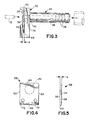
- the rear wall 33 of the housing 32 includes an aperture 40 which extends entirely through the housing 32 and communicates with the through aperture 36 in the nipple 34.
- air flowing through the nipple 34 is able to pass entirely through the rear wall 33 of the housing 32.
- the sensor target housing 32 further comprises a bottom wall 44 extending generally orthogonally from the planar front face 42 of the rear wall 33, and a front wall 46 disposed in generally spaced parallel relationship to the front face 42.
- the spaced relationship of the front wall 46 from the planar front face 42 defines a target mounting groove 48 of width "a" in the housing 32.
- the front wall 46 is further characterized by a pair of apertures 52 extending therethrough and into the area defined by the mounting groove 48.
- the apertures 52 are reamed dowel pin holes which permit the apertures 52 to receive hinge pins for laterally aligning the sensor target 28 in the mounting groove 48 and thereby preventing the sensor target 28 from "walking" out of the mounting groove 48 after repeated use.
- the side of the front wall 46 facing the mounting groove 48 defines a step 54, the dimensions of which are selected in accordance with the amount of angular pivoting preferred for the sensor target 28.
- the sensor target 28 is illustrated in greater detail in FIGS. 4 and 5. More particularly, the sensor target 28 is of generally planar rectangular configuration with opposed front and rear faces 56 and 58, opposed side edges 60 and 62, a top edge 64 and a bottom edge 66. The target 28 defines a thickness "b" between the front and rear surfaces 56 and 58 thereof which is less than the width "a" of the groove 48 in the housing 32. The width of the sensor target 28, as measured between the side edges 60 and 62, and the height thereof as measured between the top and bottom edges 64 and 66 substantially corresponds to the dimensions of the front face 42 on the rear wall 33 of housing 32.
- the edge of the target 28 extending along the intersection of the bottom 66 and the rear surface 58 thereof is generally arcuate to facilitate a pivotal movement of the sensor target 28 within the mounting groove 48 of the housing 32.
- the sensor target 28 is further characterized by apertures 72 which align with the apertures 62 in the front wall 46 of the housing 32, to receive hinge pins and enable positive lateral alignment of the sensor target 28.
- the rear face 58 of the sensor target 28 is unsmooth and nonplanar, and in particular is characterized by a generally circular recessed portion 74 which is disposed for alignment with the aperture 40 in the rear wall 33 of the housing 32.
- the recessed portion 74 functions as an air flow control means which substantially localizes the forces exerted by the flow of air through aperture 40 for keeping the sensor target 28 in a predetermined pivotal position, without requiring a large volume of air flow or a high speed of air flow through the aperture 40.
- the rear face 58 of the sensor target 28 is planar and smooth, the flow of air has the opposite of the anticipated effect, and causes the target 28 to pivot toward the rear wall 33 of the housing 32.
- the unsmooth and nonplanar construction afforded by the recessed portion 74 in the rear face 58 causes the air flow to urge the sensor target 28 away from the rear wall 33 of the housing 32.
- the force exerted by the air pressure to keep the sensor target 28 in a pivoted position away from the front face 42 of the rear wall 33 of housing 32 can be very low, with a 3.0 p.s.i. typically being sufficient in view of the gravitational orientation of front face 42 of the housing 32.
- the force required by the wire 12 to cause the sensor target 28 to pivot back toward the housing 32 is very low, both in view of the low air pressure exerted against the sensor target 28, and in view of the small range of angular movement from the gravitational orientation that is permitted.
- a very small gauge wire will be sufficient to pivot the sensor target 28 into face-to-face relationship with the front face 42 of the rear wall 33 of housing 32, to thereby create the back pressure that will be sensed by the apparatus depicted in FIG. 1.
- FIG. 6 An alternate embodiment of the sensor target assembly of the subject invention is depicted in FIG. 6. More particularly, the sensor target assembly 76 com strictlyprises a sensor target 78 hingedly connected to a housing 82 for pivotal movement relative thereto.
- a nipple 84 extends from the housing 82 and includes a through aperture 86 extending therethrough for delivering a flow of air to the housing 82. The flow of air may be delivered by a tube mounted over an array of external ribs 88 disposed on a portion of the nipple 84 spaced from the housing 82.
- the housing 82 further comprises a rear wall 83 having an aperture 90 extending entirely therethrough to intersect a planar front face 92 thereof.
- the housing 82 and nipple 84 depicted in FIG. 6 are substantially similar to the housing 32 and nipple 34 described above.
- the housing 82 includes no front wall adjacent the bottom of the sensor target 78 for controlling the range of pivotal movement.
- the housing 82 is characterized by a top wall 94 and a short front wall 96 extending therefrom in generally spaced parallel relationship to the front face 92 of the rear wall 83.
- the target 78 is disposed intermediate the front face 92 of the rear wall 83 and the front wall 96, such that the rotational limits of the target 78 are clearly defined.
- the sensor target assembly 76 depicted in FIG. 6 operates substantially identically to the sensor target assembly 26 described and illustrated above.
- the flow of air through the aperture 90 urges the sensor target 78 into a rotational movement away from the front face 92.
- the range of rotational movement is positively limited to a small angular amount by the front wall 96.
- the flow of air passing through the aperture 90 in the housing 82 can be maintained very low, as defined above, in view of the initial generally gravitational orientation of the front face 92 of the rear wall 83 of housing 82.
- a sensor target assembly for use with a wire stripper or terminal crimper apparatus to positively signal the presence of a small gauge wire in a position to have the insulation stripped therefrom or to have a terminal crimped thereon.
- the apparatus comprises a housing having means for delivering a low pressure flow of air therethrough.
- a sensor target is pivotally mounted to the housing such that in a first pivotal position the target permits the flow of air through the housing, while in a second pivotal position the target at least partially blocks the flow of air through the housing.
- the housing is gravitationally oriented to ensure very low forces for pivoting the sensor target throughout its range of movement. In operation the flow of air will urge the target to one extreme in its ranges of pivotal movement.
Landscapes
- Engineering & Computer Science (AREA)
- Manufacturing & Machinery (AREA)
- Measuring Arrangements Characterized By The Use Of Fluids (AREA)
- Measuring Fluid Pressure (AREA)
- Manufacturing Of Electrical Connectors (AREA)
Applications Claiming Priority (2)
| Application Number | Priority Date | Filing Date | Title |
|---|---|---|---|
| US07/243,567 US4850221A (en) | 1988-09-12 | 1988-09-12 | Wire sensing apparatus |
| US243567 | 1988-09-12 |
Publications (1)
| Publication Number | Publication Date |
|---|---|
| EP0358509A1 true EP0358509A1 (de) | 1990-03-14 |
Family
ID=22919250
Family Applications (1)
| Application Number | Title | Priority Date | Filing Date |
|---|---|---|---|
| EP89309090A Ceased EP0358509A1 (de) | 1988-09-09 | 1989-09-07 | Drahttaster |
Country Status (3)
| Country | Link |
|---|---|
| US (1) | US4850221A (de) |
| EP (1) | EP0358509A1 (de) |
| JP (1) | JPH0682048B2 (de) |
Cited By (3)
| Publication number | Priority date | Publication date | Assignee | Title |
|---|---|---|---|---|
| EP0673099A3 (de) * | 1994-03-16 | 1998-03-18 | Komax Holding Ag | Verfahren zum Abtrennen und/oder Abisolieren sowie eine Vorrichtung zur Durchführung dieses Verfahrens |
| EP1355388A3 (de) * | 2002-04-19 | 2004-10-13 | Tyco Electronics Corporation | Drahtpositioniereinrichtung, Vorrichtung, Verfahren und Herstellungsgegenstände |
| CN104167655A (zh) * | 2014-07-26 | 2014-11-26 | 昆山立讯精密模具有限公司 | 精密去皮机 |
Families Citing this family (4)
| Publication number | Priority date | Publication date | Assignee | Title |
|---|---|---|---|---|
| WO1992022781A1 (en) * | 1991-06-10 | 1992-12-23 | Inter-City Products Corporation (Usa) | Condensing unit using cross-flow blower |
| NL2003874C2 (nl) * | 2009-11-26 | 2011-05-30 | Vmi Holland Bv | Bandenbouwtrommel met opslagmechanisme. |
| JP6045241B2 (ja) * | 2012-08-01 | 2016-12-14 | Mcm Cosmic株式会社 | 電線被覆材剥離装置 |
| US11143778B2 (en) | 2019-10-18 | 2021-10-12 | TE Connectivity Services Gmbh | Cable end sensing apparatus and method |
Citations (3)
| Publication number | Priority date | Publication date | Assignee | Title |
|---|---|---|---|---|
| EP0037083A2 (de) * | 1980-04-02 | 1981-10-07 | Grote & Hartmann GmbH & Co. KG | Kontaktfahnenanordnung für eine Abisoliervorrichtung |
| US4322590A (en) * | 1979-10-22 | 1982-03-30 | Martin Sobel | Pneumatic remote sensing apparatus |
| US4601093A (en) * | 1984-09-21 | 1986-07-22 | Eubanks Engineering Co. | Wire insulation stripping apparatus |
Family Cites Families (1)
| Publication number | Priority date | Publication date | Assignee | Title |
|---|---|---|---|---|
| US3407505A (en) * | 1965-06-25 | 1968-10-29 | Moore Products Co | Pneumatic dimension gages |
-
1988
- 1988-09-12 US US07/243,567 patent/US4850221A/en not_active Expired - Fee Related
-
1989
- 1989-09-07 EP EP89309090A patent/EP0358509A1/de not_active Ceased
- 1989-09-08 JP JP1234560A patent/JPH0682048B2/ja not_active Expired - Lifetime
Patent Citations (3)
| Publication number | Priority date | Publication date | Assignee | Title |
|---|---|---|---|---|
| US4322590A (en) * | 1979-10-22 | 1982-03-30 | Martin Sobel | Pneumatic remote sensing apparatus |
| EP0037083A2 (de) * | 1980-04-02 | 1981-10-07 | Grote & Hartmann GmbH & Co. KG | Kontaktfahnenanordnung für eine Abisoliervorrichtung |
| US4601093A (en) * | 1984-09-21 | 1986-07-22 | Eubanks Engineering Co. | Wire insulation stripping apparatus |
Cited By (4)
| Publication number | Priority date | Publication date | Assignee | Title |
|---|---|---|---|---|
| EP0673099A3 (de) * | 1994-03-16 | 1998-03-18 | Komax Holding Ag | Verfahren zum Abtrennen und/oder Abisolieren sowie eine Vorrichtung zur Durchführung dieses Verfahrens |
| EP1355388A3 (de) * | 2002-04-19 | 2004-10-13 | Tyco Electronics Corporation | Drahtpositioniereinrichtung, Vorrichtung, Verfahren und Herstellungsgegenstände |
| CN104167655A (zh) * | 2014-07-26 | 2014-11-26 | 昆山立讯精密模具有限公司 | 精密去皮机 |
| CN104167655B (zh) * | 2014-07-26 | 2016-03-02 | 昆山立讯精密模具有限公司 | 精密去皮机 |
Also Published As
| Publication number | Publication date |
|---|---|
| JPH0682048B2 (ja) | 1994-10-19 |
| JPH02176412A (ja) | 1990-07-09 |
| US4850221A (en) | 1989-07-25 |
Similar Documents
| Publication | Publication Date | Title |
|---|---|---|
| US4871330A (en) | Electrical connector construction | |
| US3805214A (en) | Resilient electrical contact | |
| US7338293B2 (en) | Circuit contact to test apparatus | |
| US4988311A (en) | Terminal blocks | |
| US4625386A (en) | Combination tool | |
| US4897040A (en) | Cutting and clamp sleeve contact and method of connecting insulated electrical wire conductors | |
| US4850221A (en) | Wire sensing apparatus | |
| EP0419849A1 (de) | Verfahren und Vorrichtung zum Verschmelzen von Läufer und Ständerdrähten | |
| TW201112510A (en) | Plug connector | |
| EP0251736A2 (de) | Drahthaltevorrichtung in einem elektrischen Steckverbinder | |
| WO1986006559A1 (en) | Apparatus for slitting the shield of a flat cable | |
| EP0002111A1 (de) | Drahtverbindungsvorrichtung sowie Kombination der Vorrichtung und eines elektrischen Verbinders | |
| US4677702A (en) | Wire insulation stripper guide | |
| US4888864A (en) | Apparatus for mounting cable on a connector | |
| US5903971A (en) | Wire termination apparatus for making wire harnesses | |
| US5020216A (en) | Apparatus for loading cable on connector | |
| US4611874A (en) | Device for making LSA-PLUS contact with conductor wires of different types and sizes | |
| EP4718643A1 (de) | Vorrichtung und verfahren zum schneiden und einfügen eines aussenleiters | |
| US5390410A (en) | Terminal crimping apparatus | |
| EP4285449B1 (de) | Crimpvorrichtung für elektrische anschlussklemmen zur verhinderung der entfernung von fehlerhaften crimps | |
| JP2007151289A (ja) | 導通式ストリップ刃設定方法および装置 | |
| JP4337103B2 (ja) | 電線装着装置、及び挿入構造 | |
| JPH10178299A (ja) | 端子挿入装置 | |
| US5124644A (en) | System for positioning a semiconductor chip package with respect to a testing device | |
| US5363549A (en) | Cable laminating and terminating system |
Legal Events
| Date | Code | Title | Description |
|---|---|---|---|
| PUAI | Public reference made under article 153(3) epc to a published international application that has entered the european phase |
Free format text: ORIGINAL CODE: 0009012 |
|
| AK | Designated contracting states |
Kind code of ref document: A1 Designated state(s): DE FR GB |
|
| 17P | Request for examination filed |
Effective date: 19900822 |
|
| 17Q | First examination report despatched |
Effective date: 19920611 |
|
| STAA | Information on the status of an ep patent application or granted ep patent |
Free format text: STATUS: THE APPLICATION HAS BEEN REFUSED |
|
| 18R | Application refused |
Effective date: 19931209 |