EP3885233A1 - Schienendetektor mit mechanischer zeitschaltuhr - Google Patents
Schienendetektor mit mechanischer zeitschaltuhr Download PDFInfo
- Publication number
- EP3885233A1 EP3885233A1 EP21154543.9A EP21154543A EP3885233A1 EP 3885233 A1 EP3885233 A1 EP 3885233A1 EP 21154543 A EP21154543 A EP 21154543A EP 3885233 A1 EP3885233 A1 EP 3885233A1
- Authority
- EP
- European Patent Office
- Prior art keywords
- wheel
- detector according
- timing
- rotation
- railroad
- Prior art date
- Legal status (The legal status is an assumption and is not a legal conclusion. Google has not performed a legal analysis and makes no representation as to the accuracy of the status listed.)
- Pending
Links
- 230000009471 action Effects 0.000 claims abstract description 25
- 230000003111 delayed effect Effects 0.000 claims description 3
- 239000007788 liquid Substances 0.000 description 5
- 230000000284 resting effect Effects 0.000 description 5
- 230000004913 activation Effects 0.000 description 4
- 230000003213 activating effect Effects 0.000 description 3
- 238000009434 installation Methods 0.000 description 3
- 230000008901 benefit Effects 0.000 description 2
- 230000008859 change Effects 0.000 description 2
- 238000013016 damping Methods 0.000 description 2
- 238000010586 diagram Methods 0.000 description 2
- BASFCYQUMIYNBI-UHFFFAOYSA-N platinum Chemical compound [Pt] BASFCYQUMIYNBI-UHFFFAOYSA-N 0.000 description 2
- 229920003229 poly(methyl methacrylate) Polymers 0.000 description 2
- 239000004926 polymethyl methacrylate Substances 0.000 description 2
- 230000009467 reduction Effects 0.000 description 2
- 230000001960 triggered effect Effects 0.000 description 2
- 241000037488 Coccoloba pubescens Species 0.000 description 1
- 240000008042 Zea mays Species 0.000 description 1
- 230000000712 assembly Effects 0.000 description 1
- 238000000429 assembly Methods 0.000 description 1
- 230000004888 barrier function Effects 0.000 description 1
- 239000003638 chemical reducing agent Substances 0.000 description 1
- 230000001934 delay Effects 0.000 description 1
- 238000001514 detection method Methods 0.000 description 1
- 230000000694 effects Effects 0.000 description 1
- 238000009429 electrical wiring Methods 0.000 description 1
- 238000004519 manufacturing process Methods 0.000 description 1
- 230000007246 mechanism Effects 0.000 description 1
- 239000004033 plastic Substances 0.000 description 1
- 229920003023 plastic Polymers 0.000 description 1
- 230000002028 premature Effects 0.000 description 1
- 238000009877 rendering Methods 0.000 description 1
- 239000007787 solid Substances 0.000 description 1
- 230000003313 weakening effect Effects 0.000 description 1
Images



Classifications
-
- B—PERFORMING OPERATIONS; TRANSPORTING
- B61—RAILWAYS
- B61L—GUIDING RAILWAY TRAFFIC; ENSURING THE SAFETY OF RAILWAY TRAFFIC
- B61L23/00—Control, warning or like safety means along the route or between vehicles or trains
- B61L23/04—Control, warning or like safety means along the route or between vehicles or trains for monitoring the mechanical state of the route
- B61L23/042—Track changes detection
- B61L23/047—Track or rail movements
-
- B—PERFORMING OPERATIONS; TRANSPORTING
- B61—RAILWAYS
- B61L—GUIDING RAILWAY TRAFFIC; ENSURING THE SAFETY OF RAILWAY TRAFFIC
- B61L13/00—Operation of signals from the vehicle or by the passage of the vehicle
- B61L13/002—Operation of signals from the vehicle or by the passage of the vehicle actuated by the passage of the vehicle
-
- B—PERFORMING OPERATIONS; TRANSPORTING
- B61—RAILWAYS
- B61L—GUIDING RAILWAY TRAFFIC; ENSURING THE SAFETY OF RAILWAY TRAFFIC
- B61L29/00—Safety means for rail/road crossing traffic
- B61L29/08—Operation of gates; Combined operation of gates and signals
- B61L29/18—Operation by approaching rail vehicle or train
Definitions
- the invention relates to railway detectors placed on railway tracks so that, during the passage of trains, these detectors are actuated by the first wheel of the train and generate a control signal, following which an operator can, for example, control passage barriers. level, traffic lights, announcements, ... etc.
- These detectors therefore include one or more arms, arranged to be rotated and driven in by the wheels.
- the arm acting as a crank will, by its rotation, actuate a device which will create an electrical contact. This will be maintained by a time delay.
- crank does not return to the rest state until after a certain time so as not to be driven again by the wheels of the trains following the first ones in order to avoid premature wear of the arms (crank). in contact with the wheels.
- the existing time delay on mechanical detectors systematically uses a hydraulic time delay.
- the hydraulic devices of railway detectors which are damping devices, comprise, in a cylinder mounted inside a housing, a piston that a lever, fixed to the crank, moves very quickly in one direction, which, by suction, opens a valve mounted in end of the cylinder and through which a liquid, usually oil, enters the cylinder.
- the piston is driven by the lever, in the direction of filling the cylinder, against the action of return means, generally a large leaf spring.
- the liquid in the cylinder, pushed by the piston is evacuated in a leakage current in a drain member, in this case a needle screw cooperating with a conical seat of the drain valve.
- the liquid then returns to the housing of the timing device for the next cycle. It is when the piston is at the end of its suction stroke, and therefore at the start of its delivery or discharge stroke, that the time delay begins, but it is as soon as it is moved by the lever that the electrical contact is established.
- the needle screw of leakage current hydraulic devices is mounted at the end of a rod positioned relative to the seat of the drain valve as a function of the delay time, to vary the duration by adjusting the annular space around the valve. needle screw and therefore the flow speed of the liquid.
- the time delay is therefore a function of the flow rate defined by the needle screw, in other words of the closure of the seat.
- the time delay setting is particularly delicate.
- the range of variation of the time delay which extends, in theory, from 0 to 25 seconds, corresponds to a rotation of the needle screw at the end of the rod by a single turn. Going from 10 to 15 seconds means that you can only turn the needle screw a fifth of a turn. Such precision is risky.
- the detection of the orientation of the passage of the train is done in all known systems by a selection V.
- a rod (operated by a lever), or directly the arm, moves on one of the ramps of a V depending on whether the train is coming from the right or from the left.
- the invention of the present application aims to eliminate the problems posed by the leakage current railway detectors of the prior art.
- the advantage of the invention lies in the fact that the violence of the impact of the train wheel on the crank arm is avoided.
- a rotary mechanical timer arranged to be driven in rotation only during the return to the rest position of the rod for establishing the electrical contact.
- a freewheel mounted on the arm designed to trigger the time delay when the rod for establishing the electrical contact is returned to the rest position.
- the freewheel is integral in rotation with a toothed wheel engaged on a gear wheel of a gear train of the rotary timer.
- the mechanical timer can be a timer with adjustable friction brake, insensitive to temperature variations.
- it is the freewheel which is arranged to secure in rotation the gear train and the rotary arm.
- the timing wheel is mounted in a timing module arranged to secure it to the gear train and means are provided for causing the timing to end.
- the timing module includes a braking pendulum and that the timing wheel and the braking pendulum are arranged so that the pendulum can slow down the rotation of the timing wheel.
- the means of the invention have the advantage of being independent of the temperature, the influence of which is almost zero in the operating range of a railway detector, of the order of - 30 ° C to + 70 ° C.
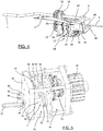
- the detector as shown, comprises a rotating crank arm 1, on which a train wheel 50 can strike.
- a lever 2 is integral in rotation with the arm 1, against the action of a leaf spring 3.
- the lever 2 is arranged to move a selection rod 4 against the action of a spring return rod 41.
- the selection rod can act on two switches 9, 10 arranged to actuate two groups of switches 12, 13.
- the selection rod is therefore a rod for establishing an electrical contact which generates a control signal 101.
- the return of the selection rod 4 to the rest position is timed by a chain of exclusively mechanical means 100, referred to as a rotary mechanical timer, and comprising a freewheel 39, a gear train 33, 34 and the means specific time delays described below.
- a chain of exclusively mechanical means 100 referred to as a rotary mechanical timer, and comprising a freewheel 39, a gear train 33, 34 and the means specific time delays described below.
- the detector comprises, for each direction, a crank arm 1, 1 'rotatably mounted in bearings of the frame 100 of the detector.
- a lever 2, 2 ' Solid with each rotary arm, a lever 2, 2 ', therefore arranged to be driven in rotation in one direction and in the other with the arm, is subjected to the action of a leaf spring 3, 3' - it can there are several associated with each lever - to recall it in the opposite direction of rotation to that caused by the passage of a train wheel on the crank arm 1, 1 '.
- the lever 2, 2 ' is shaped to drive in movement a single rod 4, called a selection rod, introduced into a single selection slot 5 of a plate 26 of the detector frame.
- the rod 4 is common to both directions.
- the slot 5 is a slot with two V-shaped ramps 6, 7, for the two directions of passage of the trains, respectively, serving to guide the rod 4 during its movement by the lever 2, 2 'along one of the two ramps 6, 7.
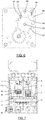
- this electrical assembly comprises two contactors 9, 10, of which the switch 9 is associated with the arm 1 and the lever 2.
- the end of the rod 4 protrudes out of the ramp 7 from the slot 5 on the figure 9 . It was engaged there by the passage of a train on arm 1.
- the rod 4 will be referred to as the selection rod. Indeed, as regards the arm 1, the lever 2 can only push the rod 4 along the ramp 7 of the slot 5.
- the contactors 9, 10 are mounted to pivot about an axis 30 mounted on the plate 26. Still associated with the arms 1, 1 'are arranged on the plate 26, for safety, two groups of switches 12, 13, identical, shown. to the figure 4 in their resting position and operating in parallel. Each of these four switches comprises a rest pad 14 and a pad 15 for activating the electrical contact and, between the two, a pad 16 for establishing the electrical contact carried by a leaf spring 17 naturally biased towards the activation pad. 15.
- Each contactor 9, 10 here comprises an arm 18, mounted on the shaft 30, extended by a plate 19 forming an elbow with the arm 18 and shaped and arranged to cooperate with the switches 12, 13 and the rod 4.
- the plates 19 carry two teeth 20, 21 projecting and cooperating with the leaf springs 17 of the switches.
- the contactor 10 is free to pivot about its axis 30, the teeth 20, 21 of the contactor 10 have then been pushed by their leaf springs 17 under the action of their spring function which thus drives the contactor, and here the contactor 10, in clockwise rotation on the figure 9 , while the leaf springs 17 of the switches 13 turn, so to speak, counterclockwise.
- the plates 19 have a rear edge 22 with which the rod 4 can cooperate, an edge which extends, during the cooperation, substantially parallel to the ramp in which the rod 4 is located.
- One freewheel 39 ( figures 2 and 4 ) is mounted on each arm 1, 1 ', which it is therefore integral in rotation in one direction. During the impact of a train wheel on an arm, the rotation of the arm takes place in the free direction of the wheel 39, therefore without effort on the mechanical elements downstream of the free wheel 39.
- the freewheel 39 is rotatably attached to a toothed wheel 32 engaged on a gear wheel 33 at the input of a gear train 34.
- the chain 100 which begins with the freewheel 39, ends with the rotary mechanical timer which will now be described.
- Gear train 34 comes out on an adjustable friction brake 35, here resting against the shaft 36 of the gear train.
- Freewheel 39 ( figure 2 ) is mounted on a sleeve 31 broached on each arm 1, 1 ', which it is therefore integral in rotation in one direction.
- Chain 100 which begins with freewheel 39, ends with brake 35.
- the gear train is preferably a commercial multi-stage planetary multiplier reducer allowing high reduction in a small space.
- the wheel 33 is therefore the input wheel of the gear train 34 which is in fact a reduction gear to reduce the low rotation of the wheel 33 driven by the arm 1 via the wheel 32 when it is secured to the arm.
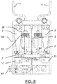
- the output shaft 70 of the train 34 extends to the interior of a timing module 75 by carrying at its end, inside the module, the first disc 76 of a clutch therefore with discs 77
- the clutch 77 comprises a second disc 78 mounted on a clutch shaft 79 carrying, inside the timing module 75, a first idler gear 80 meshing with a second idler gear 81 mounted at the end of a timing tree 82.
- the disks 76, 78 of the clutch 77 are formed here to cooperate by friction.
- the timing shaft 82 carries a timing toothed wheel 83, the teeth 84 of which are angularly relatively spaced from each other, here about 45 °.
- a braking pendulum 85 is mounted to pivot freely on an axis 86, here between the timing wheel 83 and the second return pinion 81.
- the braking pendulum 85 here in the shape of a crescent, carries in perpendicular projection, therefore parallel to the shafts 79, 82 and to the axis 86, two pins 87, 88 which extend, towards the train 34, beyond the teeth 84 of the timing wheel 83.
- timing wheel 83 when the timing wheel 83 is rotated, here counterclockwise on the figure 6 , by the toothed wheel 33, driven by the wheel 32 then secured to the arm 1 and to the lever 2 when the selection rod 4 returns to the rest position, the timing wheel 83 is thwarted in its rotation by the pendulum 85 and its pins 87, 88.
- the tooth 89 then causes the pendulum 85 to tilt clockwise before the pin 88 strikes the tooth 84 of the wheel 83, i.e. here the second tooth before the tooth 89, and the pendulum 85 switches back. counterclockwise.
- the pendulum 85 becomes animated with a reciprocating pivoting movement, around its axis 86 to brake the timing wheel 83 until the end of the timing which will be explained below.
- the timing wheel 83 in its slowed down rotational movement, also drives the arm 1 in a slow manner via the shaft 82, the idler gears 81, 80, the shaft 79, the clutch 77 , the gear train 34 and the wheels 33, 32 until the clutch 77 has become inoperative.
- timing module 75 constitute the set of means arranged to secure in rotation the gear train 34 and the timing wheel 83.
- the pendulum 85 constitutes the means controlling the speed of rotation of the timing wheel 83.
- Means are also provided for causing the termination of the time delay.
- timing switch finger 91 On the outside of the external flange 90 of the timing module 75 is mounted a timing switch finger 91.
- This finger which is bent, is pivotally mounted around a rod 92 anchored in a bracket 93 fixed to the outside of the flange, and against the action of a spring 94, here of torsion, which recalls the portion of the finger away from the caliper in the rest position perpendicular to the flange 90.
- Clutch shaft 79 extends through flange 90 to protrude slightly from the flange.
- the shaft 79 is movable in translation through the flange. The amplitude of the translation is sufficiently low so that the idler gear 80 mounted on the shaft 79 always remains meshed with the other idler gear 81.
- a screw 95 for controlling the end of the delay is fixed to the finger 91, parallel to it and to protrude in an adjustable manner. Those skilled in the art will easily conceive of this adjustment.
- the selection rod 4 is located inside 23 of the two bends formed between the plates 19 and the arms 18 of the contactors 9, 10 and blocks their rotation.
- the leaf springs 17 of the switches of group 13 threw their pads 16 of electrical contact on the studs 15 of activation of the electrical contact.
- the rod 4 having been pushed back to the bottom of the ramp 7 by the passage of the first wheel of a train on the crank arm 1, under the action of its return rod 41 in the rest position, inside the elbows of the contactors 9, 10, will therefore begin to slide along this ramp 7, but in a slowed manner, that is to say delayed.
- the gear train 34 enables the rotation of the crank arm to be reduced and the timing to be finely adjusted. More particularly, with regard to the second embodiment, the clutch 77 being cut in the rest position of the detector, when a train arrives on the detector, it rotates in one direction the arm 1, the lever 2, against the action of the spring 3, and the foot 98 of the lever 2 raises the selection rod 4 in the one of the two ramps 6, 7 of the slot 5.
- the timing switch finger 91 Due to the pivoting of the lever 2, and therefore of its leg 96, the timing switch finger 91 becomes free to pivot in its rest position under the action of its spring 94. Its screw 95 then pushes the shaft 79 to drive. the disc 78 against the disc 76 and therefore make the clutch 77 functional.
- the timing wheel 83 driven in rotation, is however braked by the pendulum 85 and all the wheels of the kinematic chain are also slowed down.
- the lever 2 also pivots and comes at a given instant t, by its leg 96, to pivot the finger 91, against the action of its spring 94, to release, by its screw 95, the shaft 79 and cut the clutch. 77.
- t is the instant of the end of the time delay and depends on the length of the screw 95 projecting outside the finger 91. This length is naturally adjustable to adjust the inclination of the finger 91 on the flange 90 in the rest position and therefore to control the desired time of the end of the timer.
- the detector which has just been described, in its two embodiments, is a detector with two arms 1, 1 '.
- the first arm which is struck by a train wheel moves the selector rod 4 in the V-shaped slot 5, which renders the second arm inoperative on the selector rod. Thanks to this, we can therefore detect the direction of movement of the train.
- switches of one of the two groups are triggered when a train passes in one direction, the switches of the other of the two groups, when a train passes in the other direction.
- the inertia and friction in the gear train 34 creates a timing anyway, which is the minimum timing, without activating the friction brake of the first embodiment or the timing module 75 of the second embodiment. .
- the friction brake 35 here resting against the shaft 36 of the gear train 34, makes it possible to slow down the rotation of the train. It is thus possible to increase or decrease the return time to the initial position of the selection rod 4.
- the toothed wheel 32 normally integral in rotation with the free wheel 39, could be disengageable and, when it is disengaged, the time delay then becomes zero, which makes it possible to count the axles of the train.
- the two-way detector which has just been described makes it possible to detect the coming of a train from the right, or from the left or in both directions.
- the detector here comprises a single external socket 60 and two selectors make it possible to select one of the three options.
- the switches 13 are triggered during the passage of a train coming from the right, the switches 12, during the passage of a train coming from the left.
- the two switches of one of the two groups 12, 13 are used, to detect the double direction of passage, a detector from each of the two groups 12, 13.
- the detector is provided with only one crank arm, this detector could only detect the passage of a train, without distinction of direction. But it is an option which is not necessarily negligible.
Landscapes
- Engineering & Computer Science (AREA)
- Mechanical Engineering (AREA)
- Train Traffic Observation, Control, And Security (AREA)
Applications Claiming Priority (2)
| Application Number | Priority Date | Filing Date | Title |
|---|---|---|---|
| FR2002795A FR3108301B1 (fr) | 2020-03-23 | 2020-03-23 | Détecteur ferroviaire à temporisateur mécanique |
| FR2012121A FR3116503B1 (fr) | 2020-11-25 | 2020-11-25 | Détecteur ferroviaire à temporisateur mécanique |
Publications (1)
| Publication Number | Publication Date |
|---|---|
| EP3885233A1 true EP3885233A1 (de) | 2021-09-29 |
Family
ID=74215838
Family Applications (1)
| Application Number | Title | Priority Date | Filing Date |
|---|---|---|---|
| EP21154543.9A Pending EP3885233A1 (de) | 2020-03-23 | 2021-02-01 | Schienendetektor mit mechanischer zeitschaltuhr |
Country Status (1)
| Country | Link |
|---|---|
| EP (1) | EP3885233A1 (de) |
Cited By (2)
| Publication number | Priority date | Publication date | Assignee | Title |
|---|---|---|---|---|
| FR3139312A1 (fr) * | 2022-09-06 | 2024-03-08 | Snic Rail | Dispositif de détection du trafic ferroviaire |
| WO2024068324A1 (fr) * | 2022-09-29 | 2024-04-04 | Vossloh Cogifer | Détecteur de circulation ferroviaire |
Citations (3)
| Publication number | Priority date | Publication date | Assignee | Title |
|---|---|---|---|---|
| US327576A (en) * | 1885-10-06 | Fbank i | ||
| FR2473449A1 (fr) * | 1980-01-09 | 1981-07-17 | Saxby | Pedale a effet magnetique pour detecter le passage des roues de wagons sur une voie de chemin de fer |
| GB2123590A (en) * | 1982-07-13 | 1984-02-01 | Dale | Rail car sensor |
-
2021
- 2021-02-01 EP EP21154543.9A patent/EP3885233A1/de active Pending
Patent Citations (3)
| Publication number | Priority date | Publication date | Assignee | Title |
|---|---|---|---|---|
| US327576A (en) * | 1885-10-06 | Fbank i | ||
| FR2473449A1 (fr) * | 1980-01-09 | 1981-07-17 | Saxby | Pedale a effet magnetique pour detecter le passage des roues de wagons sur une voie de chemin de fer |
| GB2123590A (en) * | 1982-07-13 | 1984-02-01 | Dale | Rail car sensor |
Cited By (5)
| Publication number | Priority date | Publication date | Assignee | Title |
|---|---|---|---|---|
| FR3139312A1 (fr) * | 2022-09-06 | 2024-03-08 | Snic Rail | Dispositif de détection du trafic ferroviaire |
| EP4335719A1 (de) * | 2022-09-06 | 2024-03-13 | SNIC Rail | Vorrichtung zur erkennung von eisenbahnverkehr |
| EP4335720A1 (de) * | 2022-09-06 | 2024-03-13 | SNIC Rail | Vorrichtung zur erkennung von eisenbahnverkehr |
| WO2024068324A1 (fr) * | 2022-09-29 | 2024-04-04 | Vossloh Cogifer | Détecteur de circulation ferroviaire |
| FR3140338A1 (fr) * | 2022-09-29 | 2024-04-05 | Vossloh Cogifer | Détecteur de circulation ferroviaire |
Similar Documents
| Publication | Publication Date | Title |
|---|---|---|
| EP3581742B1 (de) | Flächenbündiger türgriff und verfahren zum betrieb davon | |
| EP0358738B1 (de) | Mehrachsiger mechanischer manipulator mit überlastschutz | |
| EP2073228B1 (de) | Kompakte, robuste Steuerung für elektrische Mittel- und Hochspannungsgeräte | |
| FR2792264A1 (fr) | Mecanisme de reglage irreversible | |
| WO2014005952A1 (fr) | Dispositif de lancement de cibles pour le tir sportif à départ instantané de la cible | |
| FR2600603A1 (fr) | Tendeur sur un enrouleur de ceinture de securite | |
| FR2878487A1 (fr) | Mecanisme de verrouillage d'un arbre de transmission d'un vehicule automobile | |
| CA2773972A1 (fr) | Dispositif amortisseur | |
| FR3116503A1 (fr) | Détecteur ferroviaire à temporisateur mécanique | |
| FR2477421A1 (fr) | Dispositif de blocage d'enrouleur de ceinture de securite | |
| EP0568492A1 (de) | Automatische Arretiervorrichtung für den elektronischen Motorantrieb von Türen, Fensterladen, Rolladen und dergleichen | |
| WO2020094688A1 (fr) | Dispositif d'ouverture d'urgence d'une porte d'aéronef, à débrayage rotatif | |
| FR3108301A1 (fr) | Détecteur ferroviaire à temporisateur mécanique | |
| EP3306415B1 (de) | Mechanisches uhrwerk mit erfassung der gangreserve | |
| CH329066A (fr) | Machine à écrire | |
| FR2812760A1 (fr) | Mecanisme de manoeuvre a chaine de traction pour un appareillage electrique de coupure haute tension | |
| FR3043119A1 (fr) | Systeme d’entrainement | |
| FR3096642A1 (fr) | Détecteur ferroviaire à dispositif hydraulique de temporisation | |
| FR2559284A1 (fr) | Dispositif de commande de programmateur | |
| FR2803685A1 (fr) | Mecanisme a parallelogramme articule pour l'entrainement d'un organe de contact d'un appareil electrique de coupure | |
| FR2801864A1 (fr) | Dispositif de surpassement manuel, notamment pour commande de vol d'un aeronef | |
| EP0867594A1 (de) | Automatische Bremsvorrichtung für einen Elektromotor, der ein drehendes Teil antreibt | |
| FR2927109A1 (fr) | Serrure a commande automatique et son dispositif d'actionnement permettant un fonctionnement de la serrure en mode degrade. | |
| BE875496R (fr) | Dispositif anti-chute automatique pour installation de levage motorisee | |
| FR2756320A1 (fr) | Dispositif de detection de fin de course et mecanisme d'entrainement de volet roulant incorporant un tel dispositif |
Legal Events
| Date | Code | Title | Description |
|---|---|---|---|
| PUAI | Public reference made under article 153(3) epc to a published international application that has entered the european phase |
Free format text: ORIGINAL CODE: 0009012 |
|
| STAA | Information on the status of an ep patent application or granted ep patent |
Free format text: STATUS: THE APPLICATION HAS BEEN PUBLISHED |
|
| AK | Designated contracting states |
Kind code of ref document: A1 Designated state(s): AL AT BE BG CH CY CZ DE DK EE ES FI FR GB GR HR HU IE IS IT LI LT LU LV MC MK MT NL NO PL PT RO RS SE SI SK SM TR |
|
| STAA | Information on the status of an ep patent application or granted ep patent |
Free format text: STATUS: REQUEST FOR EXAMINATION WAS MADE |
|
| 17P | Request for examination filed |
Effective date: 20211025 |
|
| RBV | Designated contracting states (corrected) |
Designated state(s): AL AT BE BG CH CY CZ DE DK EE ES FI FR GB GR HR HU IE IS IT LI LT LU LV MC MK MT NL NO PL PT RO RS SE SI SK SM TR |
|
| STAA | Information on the status of an ep patent application or granted ep patent |
Free format text: STATUS: EXAMINATION IS IN PROGRESS |
|
| 17Q | First examination report despatched |
Effective date: 20250212 |