EP0358794B1 - Appareil pour détecter la forme d'un chanfrein - Google Patents
Appareil pour détecter la forme d'un chanfrein Download PDFInfo
- Publication number
- EP0358794B1 EP0358794B1 EP88115014A EP88115014A EP0358794B1 EP 0358794 B1 EP0358794 B1 EP 0358794B1 EP 88115014 A EP88115014 A EP 88115014A EP 88115014 A EP88115014 A EP 88115014A EP 0358794 B1 EP0358794 B1 EP 0358794B1
- Authority
- EP
- European Patent Office
- Prior art keywords
- groove
- detecting
- shape
- information
- picture elements
- Prior art date
- Legal status (The legal status is an assumption and is not a legal conclusion. Google has not performed a legal analysis and makes no representation as to the accuracy of the status listed.)
- Expired - Lifetime
Links
Images


Classifications
-
- B—PERFORMING OPERATIONS; TRANSPORTING
- B23—MACHINE TOOLS; METAL-WORKING NOT OTHERWISE PROVIDED FOR
- B23K—SOLDERING OR UNSOLDERING; WELDING; CLADDING OR PLATING BY SOLDERING OR WELDING; CUTTING BY APPLYING HEAT LOCALLY, e.g. FLAME CUTTING; WORKING BY LASER BEAM
- B23K9/00—Arc welding or cutting
- B23K9/095—Monitoring or automatic control of welding parameters
- B23K9/0956—Monitoring or automatic control of welding parameters using sensing means, e.g. optical
-
- G—PHYSICS
- G06—COMPUTING OR CALCULATING; COUNTING
- G06T—IMAGE DATA PROCESSING OR GENERATION, IN GENERAL
- G06T7/00—Image analysis
- G06T7/10—Segmentation; Edge detection
- G06T7/13—Edge detection
-
- G—PHYSICS
- G06—COMPUTING OR CALCULATING; COUNTING
- G06T—IMAGE DATA PROCESSING OR GENERATION, IN GENERAL
- G06T7/00—Image analysis
- G06T7/70—Determining position or orientation of objects or cameras
- G06T7/73—Determining position or orientation of objects or cameras using feature-based methods
-
- G—PHYSICS
- G06—COMPUTING OR CALCULATING; COUNTING
- G06T—IMAGE DATA PROCESSING OR GENERATION, IN GENERAL
- G06T2207/00—Indexing scheme for image analysis or image enhancement
- G06T2207/30—Subject of image; Context of image processing
- G06T2207/30108—Industrial image inspection
- G06T2207/30136—Metal
-
- G—PHYSICS
- G06—COMPUTING OR CALCULATING; COUNTING
- G06T—IMAGE DATA PROCESSING OR GENERATION, IN GENERAL
- G06T2207/00—Indexing scheme for image analysis or image enhancement
- G06T2207/30—Subject of image; Context of image processing
- G06T2207/30108—Industrial image inspection
- G06T2207/30164—Workpiece; Machine component
Definitions
- the present invention relates to an apparatus for detecting a shape of a groove, and more particularly to an apparatus for detecting a shape of a groove which processes an image formed by an image forming device.
- the prior art apparatus for detecting a weld position has disadvantages, however, in that a necessity for illuminating light source leads to an intricate constitution of the apparatus and to a complication of the adjustment of the apparatus. In addition, there is a possibility of a mixing of the illuminating light emitted from a light source with the arc light caused by welding. This makes an illumination unequal and leads to an unsatisfactory detection of the groove.
- JP-A-59-125272 shows an apparatus for detecting a weld line including an image pick up device, a temporal integrator and a processor for correcting the welding position, depending on the detected position of the weld line.
- the shape of a weld groove is not determined.
- an apparatus for detecting a shape of a groove comprising: means for forming picture images of a groove and a groove face of a work piece of metal to be welded with the use of a welding arc as illuminating light; storage means for storing information on picture elements of the picture images formed by said means for forming picture images, being constituted in two dimensions; characterized by: integrating means for integrating the information on the picture elements stored in said storage means in a predetermined direction of a memory, in said storage means; differentiating means for differentiating the integrated information in the direction perpendicular to the predetermined direction of the memory; detecting means for detecting information on shapes of the groove and groove face on the basis of the differentiated information on the picture elements; and computing means to process welding control values on the basis of the information from the detecting means.
- Fig. 1 is a perspective view illustrating the outline of the apparatus for detecting a shape of a groove of the present invention.
- Fig. 2 is a side elevation illustrating the positions of a welding torch and an image forming device of the present invention.
- Two-dimensional image forming device 12 is set in the direction shown with an arrow symbol FA in which welding torch 10 moves.
- An extinction filter is set on the side into which light beams of image forming device 12 come.
- Image forming device 12 is placed so that the device can form an image of groove 18 and groove face 20 of work piece of metal 16 to be welded being located at from 10 to 30 mm in front of a molten pool just under welding torch 10.
- An arc light is used for the illuminating light in case of forming an image.
- Air nozzle 22 is set between welding torch 10 and image forming device 12. The end of air nozzle 22 is open toward the area in which image forming device 12 forms an image. Fumes occuring at the time of welding are removed by blowing air from air nozzle 22. As a result, a good image can be formed.
- a picture image signal which is an image forming output of image forming device 12 is inputted in signal processing device 24.
- Signal processing device 24 is composed of micro-computer 26 and memory 28. In signal processing device 24, a predetermined image processing of a specific area is carried out, and a position of a welding line, the center of the groove and the width of a root gap are detected.
- the results of processing in signal processing device 24 are inputted in weld controlling device 30, being delayed by a period of time corresponding to the distance L shown in Fig. 2.
- Weld controlling device 30 controls welding current, arc voltage, deposition amount, welding speed and the like.
- Fig. 3 is a block diagram showing a constitution of the signal processing device of the present invention.
- a picture image signal from image forming device 12 is inputted in controlling section 32.
- Controlling section 32 is connected to memory 28 and processing section 34 respectively.
- Processing section 34 is composed of integrating means 36, differentiating means 38, detecting means 40 and computing means 42.
- Control section 32 has a function of storing in memory 28 a picture image signal to be inputted after the picture image signal has been subjected to A/D conversion, and a function of reading out the data of the predetermined area from memory 28 and of outputting the data with delay in weld controlling device 30.
- a period of time of the delay corresponds to the distance L shown in Fig. 2.
- Memory 28 is constituted in two dimensions. Any brightness or any quantity of light can be investigated by designating coordinate values X and Y.
- integrating means 36 integration is carried out by summing up the brightness of the picture elements lined up in a predetermined direction of memory 28.
- the reason why the integral process is carried out is to decrease an influence of a noise by coordinating contours of picture images.
- Differentiating means 38 has a purpose of taking out the contours of the picture images by differentiating the integrated picture images.
- Detecting means 40 and computing means 42 aim at obtaining information on a shape of groove 18 from the differentiated picture images.
- Detecting means 40 is provided with limiter 44.
- Limiter 44 is set to control a large fluctuation of detected positions due to a false detection.
- an arc light is used as an illuminating light. Therefore, a luminous intensity of groove 18 which is a subject of image forming device 12 is unstable and varies constantly. Because of this, the picture images are not subjected to a binalizing process, but to the integrating process and the differentiating process.
- Fig. 4 is a flow chart illustrating the work of the apparatus for detecting a shape of a groove of the present invention.
- Step A Initial setting:
- Step B Input of picture image
- a picture image signal of groove 18 formed by image forming device 12 is subjected to A/D conversion by the control section and further stored in memory 28.
- control section 32 only limited areas shown with dashed lines are set as processing areas.
- a picture element data in the areas is read out from memory 28 and the signal processing which follows is carried out.
- a position integration is carried out by integrating means 36.
- Fig. 7 indicates a brightness data of each picture element at an appropriate coordinate value X. As shown in Fig. 7, the brightness is high in an opening face 20, but low in other positions. It is difficult, however, to satisfactorily detect the edge ends GA and GB of a root gap and shoulders KA and KB due to the influence of an optical noise. Accordingly, the position integration as shown in Fig. 10 is carried out.
- Fig. 10 is an explanation of an integration of the present invention. The integration is carried out by adding brightness data at the same coordinate Y in the direction of X.
- An integral value of picture element Q1 is, for example, a value obtained by summing up the brightness of picture elements Q11 to Q15. Integral values of picture elements Q2, Q3, Q4 ... can also be obtained in the same way.
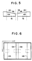
- the position integration in the direction of X is carried out relative to the specified area designated with dashed lines in Fig. 6 and an integral data of the brightness as shown in Fig. 8 is obtained.
- the integration makes it possible to coordinate the contours of the picture images relative to the direction of X and to lower relatively a level of the optical noise.
- the differentiation is carried out by differentiating means 38.
- the differentiation is carried out by finding a difference (QA-QB) of the brightness between two picture elements (QA,QB), one of the two picture elements being located at the second left to a picture element to be found and the other at the second light to the picture element.
- a difference between AQ and QB becomes QD.
- the differentiated data found in the above-mentioned way is shown in Fig. 9. There are indicated vividly peaks corresponding to the edge ends GA and GB of the root gap and to the shoulders KA and KB.
- the positions of the edge ends GA and GB of the root gap and of the shoulders KA and KB are detected and the width of the root gap are measured. That is to say, the positions of the picture elements, whose differential values indicate maximum values relative to the area shown with the dashed lines in Fig. 6, are found and detected as the positions of the edge ends GA and GB of the root gap and the shoulders KA and KB.
- Limiter 44 is set so that the maximum picture elements of the differentiated values can correspond to the positions of the edge ends GA and GB of the root gap and of the shoulders KA and KB and that there cannot be any great fluctuation of the positions to be detected, even if the maximum picture element is affected. Limiter 44 predetermines a limit of the positions to be detected and absorbs the fluctuation of the positions exceeding the set values. Then, the width of the root gap is measured based on the positions of the edge ends GA and GB of the root gap.
- Step F (Computing):
- a welding current command value and a welding speed are processed by computing means 42 on the basis of the width of the root gap measured with the use of a predetermined conversion formula.
- the welding data such as the welding current command value, the welding speed and the like, after having been stored once in memory 28 and delayed by a certain period of time, is outputted in weld controlling device 30 from controlling section 32. A difference L in distances between the position of the image formation and the welding position is removed. Accordingly, the welding current command and the welding speed command corresponding to the root gap located directly under welding torch 10 are issued.
- Step A to G Operations in Step A to G are repeated and completed when all the welding finishes.
- the position integration of the brightness of the adjacent picture elements at the same time there is carried out, as an integration, the position integration of the brightness of the adjacent picture elements at the same time.
- a time integration in which the same picture elements are integrated by time, can be carried out.
- the above-mentioned signal processing can be carried out by means of a software with the use of a computer.
- the signal processing can be carried out, however, by means of a hardware by constituting a circuit for exclusive use.
Landscapes
- Engineering & Computer Science (AREA)
- Physics & Mathematics (AREA)
- Computer Vision & Pattern Recognition (AREA)
- General Physics & Mathematics (AREA)
- Theoretical Computer Science (AREA)
- Plasma & Fusion (AREA)
- Mechanical Engineering (AREA)
- Length Measuring Devices By Optical Means (AREA)
- Image Analysis (AREA)
Claims (8)
- Appareil destiné à détecter la forme d'un chanfrein, comportant:
un dispositif (12) destiné à constituer des représentations des images d'un chanfrein (18) et de la surface d'un chanfrein (20) d'un morceau de métal de travail (16) destiné à être soudé en utilisant un arc de soudage comme lumière d'éclairage;
un dispositif de stockage (28) destiné à stocker l'information sur les éléments d'image des représentations des images formées par ledit dispositif destiné à constituer des représentations d'images, organisé selon deux dimensions;
caractérisé par:
un dispositif intégrateur (36) destiné à intégrer l'information sur les éléments d'image stockés dans ledit dispositif de stockage dans une direction prédéterminée d'une mémoire (28), dans ledit dispositif de stockage;
un dispositif différentiateur (38) destiné à différentier l'information intégrée dans la direction perpendiculaire à la direction prédéterminée de la mémoire (28);
un dispositif détecteur (40) destiné à détecter l'information relative aux formes du chanfrein et à la surface du chanfrein basé sur l'information différentiée des éléments d'image; et
un dispositif de calcul (42) destiné à traiter les valeurs de commande de soudage basé sur l'information provenant du dispositif détecteur (40). - Appareil destiné à détecter la forme d'un chanfrein selon la revendication 1, caractérisé en ce que ladite intégration comporte l'intégration de la luminance des éléments de l'image dans la direction de la ligne de soudage.
- Appareil destiné à détecter la forme d'un chanfrein selon les revendications 1 ou 2, caractérisé en ce que ladite intégration ne comporte que l'intégration de l'information des éléments d'image des parties de l'écartement de la base et des épaulements stockées dans ledit dispositif de stockage dans une direction prédéterminée d'une mémoire, dans ledit dispositif de stockage.
- Appareil destiné à détecter la forme d'un chanfrein selon les revendications 1, 2 ou 3, caractérisé en ce que ladite différentiation comporte la différentiation de la luminance intégrée des éléments de l'image dans la direction rectangulaire à la ligne de soudage.
- Appareil destiné à détecter la forme d'un chanfrein selon l'une quelconque des revendications 1 à 4, caractérisé en ce que ladite détection comporte la détection des éléments d'image ayant une valeur différentiée maximum en tant que positions des extrémités de l'écartement de la base et des épaulements.
- Appareil destiné à détecter la forme d'un chanfrein selon la revendication 5, caractérisé en ce que lesdites positions détectées des écartements de la base et des épaulements sont limitées par un limiteur (44).
- Appareil destiné à détecter la forme d'un chanfrein selon l'une quelconque des revendications 1 à 6, caractérisé en ce que ledit dispositif de calcul (42) puisse fonctionner en calculant la valeur de la commande du courant de soudage et la valeur de la commande de la vitesse de soudage basés sur l'information des formes du chanfrein et de la face du chanfrein.
- Appareil destiné à détecter la forme d'un chanfrein selon l'une quelconque des revendications 1 à 7, caractérisé en ce que ledit dispositif destiné à constituer une image possède une buse d'air (22) ouverte vers la zone de formation de l'image.
Priority Applications (3)
| Application Number | Priority Date | Filing Date | Title |
|---|---|---|---|
| US07/242,345 US4988201A (en) | 1988-09-14 | 1988-09-01 | Apparatus for detecting a shape of a groove |
| DE8888115014T DE3880835D1 (de) | 1988-09-14 | 1988-09-14 | Geraet zur bestimmung der form einer schweissnaht. |
| EP88115014A EP0358794B1 (fr) | 1988-09-14 | 1988-09-14 | Appareil pour détecter la forme d'un chanfrein |
Applications Claiming Priority (1)
| Application Number | Priority Date | Filing Date | Title |
|---|---|---|---|
| EP88115014A EP0358794B1 (fr) | 1988-09-14 | 1988-09-14 | Appareil pour détecter la forme d'un chanfrein |
Publications (2)
| Publication Number | Publication Date |
|---|---|
| EP0358794A1 EP0358794A1 (fr) | 1990-03-21 |
| EP0358794B1 true EP0358794B1 (fr) | 1993-05-05 |
Family
ID=8199309
Family Applications (1)
| Application Number | Title | Priority Date | Filing Date |
|---|---|---|---|
| EP88115014A Expired - Lifetime EP0358794B1 (fr) | 1988-09-14 | 1988-09-14 | Appareil pour détecter la forme d'un chanfrein |
Country Status (3)
| Country | Link |
|---|---|
| US (1) | US4988201A (fr) |
| EP (1) | EP0358794B1 (fr) |
| DE (1) | DE3880835D1 (fr) |
Families Citing this family (18)
| Publication number | Priority date | Publication date | Assignee | Title |
|---|---|---|---|---|
| US5086478A (en) * | 1990-12-27 | 1992-02-04 | International Business Machines Corporation | Finding fiducials on printed circuit boards to sub pixel accuracy |
| US5633950A (en) * | 1993-12-28 | 1997-05-27 | Honda Giken Kogyo Kabushiki Kaisha | Method of image processing in optical measuring apparatus |
| US5517310A (en) * | 1994-06-30 | 1996-05-14 | Solar Turbines Incorporated | Method and apparatus for obtaining and analyzing an image of a elongate slot |
| JP3573222B2 (ja) * | 1994-10-11 | 2004-10-06 | 株式会社小松製作所 | 突き合わせ溶接のワーク突き合わせ位置検出方法 |
| SE515773C2 (sv) * | 1995-12-22 | 2001-10-08 | Esab Ab | Förfarande vid automatisk flerskiktssvetsning |
| JP2791400B2 (ja) * | 1996-07-30 | 1998-08-27 | 川崎重工業株式会社 | 消耗電極式のアーク溶接方法及びアーク溶接装置 |
| US5780808A (en) * | 1997-02-28 | 1998-07-14 | Samsung Electronics Co., Ltd. | Arc sensing method in automated welding |
| US5837966A (en) * | 1997-07-23 | 1998-11-17 | Timmons, Jr.; John E. | Apparatus for weld head to pipe joint alignment for welding |
| US5959733A (en) * | 1998-05-08 | 1999-09-28 | Food Industry Research And Development Institute | Non-contact continuous photoelectric inspecting device for paint coating contamination on welding seams of steel can sheet |
| JP4037588B2 (ja) * | 1999-03-16 | 2008-01-23 | 株式会社東芝 | 原子炉制御棒の製造方法及び製造装置 |
| TW460346B (en) * | 1999-05-28 | 2001-10-21 | Hitachi Ltd | A manufacturing method of a structure body and a manufacturing apparatus of a structure body |
| JP4963182B2 (ja) * | 2006-02-23 | 2012-06-27 | ヤマザキマザック株式会社 | 3次元レーザ加工機のパイプシーム検出装置 |
| FR2923295B1 (fr) * | 2007-11-06 | 2009-12-11 | Areva Np | Procede et dispositif de visualisation et de controle du profil d'un cordon de soudure a l'interieur d'un chanfrein menage entre deux pieces metalliques |
| JP5614633B2 (ja) * | 2010-07-29 | 2014-10-29 | 国立大学法人九州工業大学 | 回転工具と被加工物間の間隙長さ測定方法及びシステム |
| US8716627B2 (en) * | 2010-09-10 | 2014-05-06 | Honeywell International Inc. | Welding systems and methods |
| US20150129581A1 (en) * | 2013-11-12 | 2015-05-14 | Lincoln Global, Inc. | System and method for pendant component for a welding system |
| USD765111S1 (en) | 2014-06-24 | 2016-08-30 | Lincoln Global, Inc. | Display screen or portion thereof with graphical user interface |
| JP2022149862A (ja) * | 2021-03-25 | 2022-10-07 | カシオ計算機株式会社 | 画像処理装置、画像処理方法、及び、プログラム |
Family Cites Families (3)
| Publication number | Priority date | Publication date | Assignee | Title |
|---|---|---|---|---|
| JPS5726706A (en) * | 1980-07-24 | 1982-02-12 | Mitsubishi Electric Corp | Detector for shape of body |
| JPS60117102A (ja) * | 1983-11-30 | 1985-06-24 | Hitachi Ltd | 溶接線倣い検出装置 |
| JPS611478A (ja) * | 1984-06-14 | 1986-01-07 | Mitsubishi Heavy Ind Ltd | 厚板自動溶接制御装置 |
-
1988
- 1988-09-01 US US07/242,345 patent/US4988201A/en not_active Expired - Fee Related
- 1988-09-14 EP EP88115014A patent/EP0358794B1/fr not_active Expired - Lifetime
- 1988-09-14 DE DE8888115014T patent/DE3880835D1/de not_active Expired - Lifetime
Also Published As
| Publication number | Publication date |
|---|---|
| DE3880835D1 (de) | 1993-06-09 |
| US4988201A (en) | 1991-01-29 |
| EP0358794A1 (fr) | 1990-03-21 |
Similar Documents
| Publication | Publication Date | Title |
|---|---|---|
| EP0358794B1 (fr) | Appareil pour détecter la forme d'un chanfrein | |
| KR100200204B1 (ko) | 아크용접공정에서용접선자동추적을위한비젼센서및비젼처리기법 | |
| US6529280B1 (en) | Three-dimensional measuring device and three-dimensional measuring method | |
| EP0532169B1 (fr) | Sonde d'inspection optique | |
| EP0426165B1 (fr) | Appareil pour l'inspection d'une plaquette à circuit imprimé | |
| JP3892838B2 (ja) | 3次元測定装置 | |
| US5104216A (en) | Process for determining the position and the geometry of workpiece surfaces | |
| US4988200A (en) | Apparatus for automatic tracking and contour measurement | |
| KR910001311B1 (ko) | 홈형상 검출 장치 | |
| GB2157851A (en) | Optical weld seam tracker | |
| Agapakis et al. | Vision sensing and processing system for monitoring and control of welding and other high-luminosity processes | |
| JP4412799B2 (ja) | 飛しょう体の照準点算定装置及び方法 | |
| JPH0453623B2 (fr) | ||
| JPS62267607A (ja) | 光切断線位置検出方法及び装置 | |
| JPS58187265A (ja) | 溶接線の位置および形状の検出方法 | |
| JPH0679416A (ja) | ロングノズルの取付位置検出装置 | |
| JPH0341306A (ja) | 断面積および体積計測装置 | |
| JPS59184804A (ja) | 光学式距離センサ | |
| JPS61191905A (ja) | 開先位置検出装置 | |
| JPH0475118B2 (fr) | ||
| JPS61103692A (ja) | レ−ザ加工機 | |
| KR940007845B1 (ko) | 단차형상 검출장치 | |
| JPS6044805A (ja) | 溶接線追尾センサ | |
| JPH01233083A (ja) | レーザ加工位置補正装置 | |
| JP2515142B2 (ja) | 画像処理による開先検出法 |
Legal Events
| Date | Code | Title | Description |
|---|---|---|---|
| PUAI | Public reference made under article 153(3) epc to a published international application that has entered the european phase |
Free format text: ORIGINAL CODE: 0009012 |
|
| 17P | Request for examination filed |
Effective date: 19880914 |
|
| AK | Designated contracting states |
Kind code of ref document: A1 Designated state(s): DE FR GB IT SE |
|
| 17Q | First examination report despatched |
Effective date: 19911030 |
|
| GRAA | (expected) grant |
Free format text: ORIGINAL CODE: 0009210 |
|
| AK | Designated contracting states |
Kind code of ref document: B1 Designated state(s): DE FR GB IT SE |
|
| PG25 | Lapsed in a contracting state [announced via postgrant information from national office to epo] |
Ref country code: IT Free format text: LAPSE BECAUSE OF FAILURE TO SUBMIT A TRANSLATION OF THE DESCRIPTION OR TO PAY THE FEE WITHIN THE PRE;WARNING: LAPSES OF ITALIAN PATENTS WITH EFFECTIVE DATE BEFORE 2007 MAY HAVE OCCURRED AT ANY TIME BEFORE 2007. THE CORRECT EFFECTIVE DATE MAY BE DIFFERENT FROM THE ONE RECORDED.SCRIBED TIME-LIMIT Effective date: 19930505 Ref country code: DE Effective date: 19930505 Ref country code: FR Effective date: 19930505 |
|
| REF | Corresponds to: |
Ref document number: 3880835 Country of ref document: DE Date of ref document: 19930609 |
|
| PG25 | Lapsed in a contracting state [announced via postgrant information from national office to epo] |
Ref country code: GB Effective date: 19930914 |
|
| PG25 | Lapsed in a contracting state [announced via postgrant information from national office to epo] |
Ref country code: SE Effective date: 19930915 |
|
| EN | Fr: translation not filed | ||
| PLBE | No opposition filed within time limit |
Free format text: ORIGINAL CODE: 0009261 |
|
| STAA | Information on the status of an ep patent application or granted ep patent |
Free format text: STATUS: NO OPPOSITION FILED WITHIN TIME LIMIT |
|
| 26N | No opposition filed | ||
| GBPC | Gb: european patent ceased through non-payment of renewal fee |
Effective date: 19930914 |
|
| EUG | Se: european patent has lapsed |
Ref document number: 88115014.8 Effective date: 19940410 |