EP0359568A2 - Selbstlaufender Abtaster zum optischen Lesen von Bildern - Google Patents
Selbstlaufender Abtaster zum optischen Lesen von Bildern Download PDFInfo
- Publication number
- EP0359568A2 EP0359568A2 EP89309353A EP89309353A EP0359568A2 EP 0359568 A2 EP0359568 A2 EP 0359568A2 EP 89309353 A EP89309353 A EP 89309353A EP 89309353 A EP89309353 A EP 89309353A EP 0359568 A2 EP0359568 A2 EP 0359568A2
- Authority
- EP
- European Patent Office
- Prior art keywords
- area
- running
- scanner
- reading
- self
- Prior art date
- Legal status (The legal status is an assumption and is not a legal conclusion. Google has not performed a legal analysis and makes no representation as to the accuracy of the status listed.)
- Granted
Links
Images




Classifications
-
- H—ELECTRICITY
- H04—ELECTRIC COMMUNICATION TECHNIQUE
- H04N—PICTORIAL COMMUNICATION, e.g. TELEVISION
- H04N1/00—Scanning, transmission or reproduction of documents or the like, e.g. facsimile transmission; Details thereof
- H04N1/0083—Arrangements for transferring signals between different components of the apparatus, e.g. arrangements of signal lines or cables
-
- H—ELECTRICITY
- H04—ELECTRIC COMMUNICATION TECHNIQUE
- H04N—PICTORIAL COMMUNICATION, e.g. TELEVISION
- H04N1/00—Scanning, transmission or reproduction of documents or the like, e.g. facsimile transmission; Details thereof
- H04N1/04—Scanning arrangements, i.e. arrangements for the displacement of active reading or reproducing elements relative to the original or reproducing medium, or vice versa
- H04N1/047—Detection, control or error compensation of scanning velocity or position
-
- H—ELECTRICITY
- H04—ELECTRIC COMMUNICATION TECHNIQUE
- H04N—PICTORIAL COMMUNICATION, e.g. TELEVISION
- H04N1/00—Scanning, transmission or reproduction of documents or the like, e.g. facsimile transmission; Details thereof
- H04N1/04—Scanning arrangements, i.e. arrangements for the displacement of active reading or reproducing elements relative to the original or reproducing medium, or vice versa
- H04N1/10—Scanning arrangements, i.e. arrangements for the displacement of active reading or reproducing elements relative to the original or reproducing medium, or vice versa using flat picture-bearing surfaces
- H04N1/1013—Scanning arrangements, i.e. arrangements for the displacement of active reading or reproducing elements relative to the original or reproducing medium, or vice versa using flat picture-bearing surfaces with sub-scanning by translatory movement of at least a part of the main-scanning components
- H04N1/1017—Scanning arrangements, i.e. arrangements for the displacement of active reading or reproducing elements relative to the original or reproducing medium, or vice versa using flat picture-bearing surfaces with sub-scanning by translatory movement of at least a part of the main-scanning components the main-scanning components remaining positionally invariant with respect to one another in the sub-scanning direction
-
- H—ELECTRICITY
- H04—ELECTRIC COMMUNICATION TECHNIQUE
- H04N—PICTORIAL COMMUNICATION, e.g. TELEVISION
- H04N1/00—Scanning, transmission or reproduction of documents or the like, e.g. facsimile transmission; Details thereof
- H04N1/04—Scanning arrangements, i.e. arrangements for the displacement of active reading or reproducing elements relative to the original or reproducing medium, or vice versa
- H04N1/10—Scanning arrangements, i.e. arrangements for the displacement of active reading or reproducing elements relative to the original or reproducing medium, or vice versa using flat picture-bearing surfaces
- H04N1/1013—Scanning arrangements, i.e. arrangements for the displacement of active reading or reproducing elements relative to the original or reproducing medium, or vice versa using flat picture-bearing surfaces with sub-scanning by translatory movement of at least a part of the main-scanning components
- H04N1/1039—Movement of the main scanning components
- H04N1/1043—Movement of the main scanning components of a sensor array
-
- H—ELECTRICITY
- H04—ELECTRIC COMMUNICATION TECHNIQUE
- H04N—PICTORIAL COMMUNICATION, e.g. TELEVISION
- H04N1/00—Scanning, transmission or reproduction of documents or the like, e.g. facsimile transmission; Details thereof
- H04N1/04—Scanning arrangements, i.e. arrangements for the displacement of active reading or reproducing elements relative to the original or reproducing medium, or vice versa
- H04N1/10—Scanning arrangements, i.e. arrangements for the displacement of active reading or reproducing elements relative to the original or reproducing medium, or vice versa using flat picture-bearing surfaces
- H04N1/1013—Scanning arrangements, i.e. arrangements for the displacement of active reading or reproducing elements relative to the original or reproducing medium, or vice versa using flat picture-bearing surfaces with sub-scanning by translatory movement of at least a part of the main-scanning components
- H04N1/1039—Movement of the main scanning components
- H04N1/1048—Movement of the main scanning components of a lens or lens arrangement
-
- H—ELECTRICITY
- H04—ELECTRIC COMMUNICATION TECHNIQUE
- H04N—PICTORIAL COMMUNICATION, e.g. TELEVISION
- H04N1/00—Scanning, transmission or reproduction of documents or the like, e.g. facsimile transmission; Details thereof
- H04N1/04—Scanning arrangements, i.e. arrangements for the displacement of active reading or reproducing elements relative to the original or reproducing medium, or vice versa
- H04N1/10—Scanning arrangements, i.e. arrangements for the displacement of active reading or reproducing elements relative to the original or reproducing medium, or vice versa using flat picture-bearing surfaces
- H04N1/1013—Scanning arrangements, i.e. arrangements for the displacement of active reading or reproducing elements relative to the original or reproducing medium, or vice versa using flat picture-bearing surfaces with sub-scanning by translatory movement of at least a part of the main-scanning components
- H04N1/1039—Movement of the main scanning components
- H04N1/1052—Movement of the main scanning components of a mirror
-
- H—ELECTRICITY
- H04—ELECTRIC COMMUNICATION TECHNIQUE
- H04N—PICTORIAL COMMUNICATION, e.g. TELEVISION
- H04N1/00—Scanning, transmission or reproduction of documents or the like, e.g. facsimile transmission; Details thereof
- H04N1/04—Scanning arrangements, i.e. arrangements for the displacement of active reading or reproducing elements relative to the original or reproducing medium, or vice versa
- H04N1/10—Scanning arrangements, i.e. arrangements for the displacement of active reading or reproducing elements relative to the original or reproducing medium, or vice versa using flat picture-bearing surfaces
-
- H—ELECTRICITY
- H04—ELECTRIC COMMUNICATION TECHNIQUE
- H04N—PICTORIAL COMMUNICATION, e.g. TELEVISION
- H04N1/00—Scanning, transmission or reproduction of documents or the like, e.g. facsimile transmission; Details thereof
- H04N1/04—Scanning arrangements, i.e. arrangements for the displacement of active reading or reproducing elements relative to the original or reproducing medium, or vice versa
- H04N1/19—Scanning arrangements, i.e. arrangements for the displacement of active reading or reproducing elements relative to the original or reproducing medium, or vice versa using multi-element arrays
- H04N1/191—Scanning arrangements, i.e. arrangements for the displacement of active reading or reproducing elements relative to the original or reproducing medium, or vice versa using multi-element arrays the array comprising a one-dimensional [1D] array
- H04N1/192—Simultaneously or substantially simultaneously scanning picture elements on one main scanning line
- H04N1/193—Simultaneously or substantially simultaneously scanning picture elements on one main scanning line using electrically scanned linear arrays, e.g. linear CCD arrays
-
- H—ELECTRICITY
- H04—ELECTRIC COMMUNICATION TECHNIQUE
- H04N—PICTORIAL COMMUNICATION, e.g. TELEVISION
- H04N2201/00—Indexing scheme relating to scanning, transmission or reproduction of documents or the like, and to details thereof
- H04N2201/04—Scanning arrangements
- H04N2201/0402—Arrangements not specific to a particular one of the scanning methods covered by groups H04N1/04 - H04N1/207
- H04N2201/0464—Self-propelled scanners, e.g. robotic scanners, means for propulsion integrated in the scanner carriage
-
- H—ELECTRICITY
- H04—ELECTRIC COMMUNICATION TECHNIQUE
- H04N—PICTORIAL COMMUNICATION, e.g. TELEVISION
- H04N2201/00—Indexing scheme relating to scanning, transmission or reproduction of documents or the like, and to details thereof
- H04N2201/04—Scanning arrangements
- H04N2201/047—Detection, control or error compensation of scanning velocity or position
- H04N2201/04701—Detection of scanning velocity or position
- H04N2201/04703—Detection of scanning velocity or position using the scanning elements as detectors, e.g. by performing a prescan
- H04N2201/04705—Detection of scanning velocity or position using the scanning elements as detectors, e.g. by performing a prescan using inactive scanning elements, e.g. elements outside the scanning area
-
- H—ELECTRICITY
- H04—ELECTRIC COMMUNICATION TECHNIQUE
- H04N—PICTORIAL COMMUNICATION, e.g. TELEVISION
- H04N2201/00—Indexing scheme relating to scanning, transmission or reproduction of documents or the like, and to details thereof
- H04N2201/04—Scanning arrangements
- H04N2201/047—Detection, control or error compensation of scanning velocity or position
- H04N2201/04701—Detection of scanning velocity or position
- H04N2201/04715—Detection of scanning velocity or position by detecting marks or the like, e.g. slits
-
- H—ELECTRICITY
- H04—ELECTRIC COMMUNICATION TECHNIQUE
- H04N—PICTORIAL COMMUNICATION, e.g. TELEVISION
- H04N2201/00—Indexing scheme relating to scanning, transmission or reproduction of documents or the like, and to details thereof
- H04N2201/04—Scanning arrangements
- H04N2201/047—Detection, control or error compensation of scanning velocity or position
- H04N2201/04701—Detection of scanning velocity or position
- H04N2201/04729—Detection of scanning velocity or position in the main-scan direction
-
- H—ELECTRICITY
- H04—ELECTRIC COMMUNICATION TECHNIQUE
- H04N—PICTORIAL COMMUNICATION, e.g. TELEVISION
- H04N2201/00—Indexing scheme relating to scanning, transmission or reproduction of documents or the like, and to details thereof
- H04N2201/04—Scanning arrangements
- H04N2201/047—Detection, control or error compensation of scanning velocity or position
- H04N2201/04701—Detection of scanning velocity or position
- H04N2201/04731—Detection of scanning velocity or position in the sub-scan direction
-
- H—ELECTRICITY
- H04—ELECTRIC COMMUNICATION TECHNIQUE
- H04N—PICTORIAL COMMUNICATION, e.g. TELEVISION
- H04N2201/00—Indexing scheme relating to scanning, transmission or reproduction of documents or the like, and to details thereof
- H04N2201/04—Scanning arrangements
- H04N2201/047—Detection, control or error compensation of scanning velocity or position
- H04N2201/04701—Detection of scanning velocity or position
- H04N2201/04732—Detecting at infrequent intervals, e.g. once or twice per line for main-scan control
Definitions
- the present invention relates to an image scanner and, more specifically, to an improvement of a scanner structured such that an object such as an original is fixedly placed and scanned by moving a scanner including an illuminating light source, a photodetector and the like to provide image information of the object.
- a scanner is one of the apparatuses provided to meet such a demand.
- the scanner is structured such that an object such as an original is illuminated by light from an illuminating light source and the light reflected from the object is detected by a one dimensional image sensor comprising CCDS (Charge Coupled Devices) to provide image information of the object.
- CCDS Charge Coupled Devices
- One type of such scanner is called a self-running type scanner in which an object such as an original is fixedly placed and a scanner portion is moved for scanning the object by using the light from the illuminating light source.
- Fig. 1 schematically shows a whole structure of a conventional self-running type scanner.
- the conventional self-running type scanner comprises a scanner unit 1 illuminating an object such as an original (not shown) with light having prescribed wavelength and for detecting light reflected from the object to provide image information of the object, and a driving portion 2 for driving running of the scanner unit 1.
- the scanner unit 1 responds through a wire 3 to the rotation of a pulse motor 4 included in the driving portion 2, to be moved along the Y direction.
- the rotation of the pulse motor 4 included in the driving portion 2 is transmitted to the wire 3 through a pulley 5b.
- a pulley 5a is similarly provided at another portion of the wire 3 so as to move smoothly the scanner unit 1 along the Y direction.
- the illuminating light from the illuminating light source included in the scanner unit 1 illuminates an object such as an original (hereinafter simply referred to as an object) while scanning the same, so that the desired image information of the object can be provided.
- an object such as an original (hereinafter simply referred to as an object) while scanning the same, so that the desired image information of the object can be provided.
- the scanner unit 1 and the driving portion 2 are contained in a scanner body 6.
- a scanner upper lid 7 is provided on the scanner body 6 for sealing the scanner unit 1, the driving portion 2 and so on, so as to prevent contamination due to dust and the like from outside.
- a plate 8 formed of a transparent material for transmitting the illuminating light from the illuminating light source included in the scanner unit 1 and the light reflected from the object is provided at a prescribed region of the scanner body 6.
- the plate 8 is formed of a material such as acryl, glass or the like which is transparent to the illuminating light from the illuminating light source therethrough.
- a white balance sheet 9 for providing a white level reference of the light reflected from the object is provided at a prescribed position of the scanner body 6.
- the scanner unit 1 scans the white balance sheet 9 to detect the light reflected from the white balance sheet sheet 9.
- the detected level of the reflected light is used as the reference level to the white level of the light reflected from the object during scanning. This is a measure to prevent erroneous reading caused by change in intensity of the reflected light associated with changes of the environment such as change in intensity of the illuminating light from the light source.
- Fig. 2 schematically shows an internal structure of the scanner unit shown in Fig. 1.
- the scanner unit comprises an illuminating light source 10 for illuminating an object, reflecting mirrors 11a, 11b, 11c and 11d reflecting the light reflected from the object (including the white balance sheet) and providing an optical path of the reflected light, and a lens 12 receiving and focusing the reflected light from the reflecting mirror 11d onto a one dimensional image sensor 13 consisting of, for example, CCDS (Charge Coupled Devices).
- the one dimensional image sensor 13 converts the applied optical signals into electric signals to transmit the same to an image information processing apparatus through a path, not shown.
- the scanner unit 1 scans the object along the Y direction
- the scanning of the object in the X direction is carried out by the one dimensional image sensor 13.
- the object is fixedly placed and illuminated by the light from the illuminating light source 10 and the illuminating light from the object is reflected by the reflecting mirrors 11a to 11d to be introduced to the one dimensional image sensor 13 through the lens 12 for image formation, so that the object can be scanned in both X and Y directions, providing desired image information of the object.
- the scanner unit 1 and the driving portion 2 for driving the running of the scanner unit 1 are separately provided, and the scanner unit 1, the driving portion 2 and the scanner driving wire 3 must be contained in a scanner body 6.
- the scanner body and the scanner upper lid both are of a separate type structure, so that the number of components of the units constituting the conventional self-running type scanner becomes large and the apparatus itself becomes complicated, preventing reduction in size of the apparatus. Since the apparatus comprises a large number of parts, it takes much time to assemble the self-running type scanner. The larger number of parts and the long time required for the assembly prevent provision of an inexpensive self-running type scanner.
- a structure of a scanner unit having a rotary motor attached integrally thereto is disclosed in Japanese Patent Laying Open No. 61-232764.
- a flanged roller which is in contact with a guiding slide rod is arranged at a tip end portion of an output axis of the rotary motor, and a fixed axis having a V grooved bearing in contact with another slide rod is provided at a tip end of the other end of the unit.
- the scanner unit moves along the slide rods by the rotation of the output axis of the rotary motor.
- a self-scanning type (self-running type) copying apparatus in which an original reading mechanism is moved by rotating a driving roller by means of a microstep motor is disclosed in Japanese Patent Laying Open No. 58-111476.
- feeding of recording paper and the scanning of the original are both carried out by the driving of the same step motor.
- No guiding means for moving the copying apparatus is provided in this prior art.
- An object of the present invention is to provide an improved self-running type scanner eliminating drawbacks of the conventional self-running type scanner.
- Another object of the present invention is to provide an inexpensive self-running type scanner having a simple structure with reduced number of parts.
- a further object of the present invention is to provide a self-running type scanner having a simple structure which can read information exactly.
- a self-running type scanner in accordance with the present invention comprises a scanner unit and a scanner driving portion formed integrally, and running assisting means for guiding and assisting the running of the scanner.
- the self-running type scanner of the present invention comprises a movable scanner portion including an illuminating light source, a photodetector for detecting reflected light, a running driving portion, and controlling means for controlling operation of the driving portion in accordance with the information detected by the photodetector, and means for guiding and assisting running of the scanner portion including means for guiding the running of the scanner portion and means indicative of a position at which reading of an object of the scanner portion starts.
- the guiding assisting means comprises a light transmitting area for defining an object reading area of the scanner portion and a white area for providing reference of white level in reading images of the object.
- scanner running driving means is integrally provided on the scanner portion, so that a simple structure can be realized, and accordingly, an inexpensive self-running type scanner can be provided as the number of parts and the steps for manufacturing can be reduced.
- Running guiding means, the reading area defining area, means for indicating reading start position and the white area provided on the running assisting means enable accurate running of the scanner portion through the controlling means provided on the scanner portion and realize accurate reading of images.
- Fig. 3 schematically shows a whole structure of the self-running type scanner in accordance with one embodiment of the present invention.
- the self-running type scanner of one embodiment of the present invention comprises a scanner portion 1′ illuminating an object while scanning the same for providing image information of the object, and a running assisting plate for guiding and assisting the running of the scanner portion 1′.
- the scanner portion 1′ comprises an illuminating light source 10 emitting light of a prescribed wavelength; reflecting mirrors 11a to 11d which reflect light reflected from objects (including an original and the like and the assisting plate 23) illuminated by the light emitted from the light source 10 for providing optical path of the reflected light; a lens 12 for condensing or converging light from the reflecting mirror 11d to form images on an image sensor 13; a one dimensional image sensor 13 converting image information of the object applied through the lens 12 into electric signals; and a controlling apparatus 20 receiving image information from the one dimensional image sensor 13 to provide desired image information and controlling the running of the scanner portion 1′.
- the controlling apparatus 20 transmits signals to external apparatuses such as an image processing apparatus through a cable 25 and receives control signals such as an image information reading instructing signal from the external apparatuses.
- the cable 25 is taken outside from the scanner portion 1′ through an upper cabinet projecting portion 24 provided on an upper portion of the upper cabinet 15 housing the scanner portion 1′.
- Front wheels 21 and rear wheels 22 for running and driving the scanner portion 1′ are also provided. The control of the operation of the front and rear wheels 21 and 22 is carried out by the controlling apparatus 20.
- the running assisting plate 23 comprises a front stopper 31 and a rear stopper 32 for preventing possible slip out of the scanner portion 1′ from the running assisting plate 23 which may lead the scanner portion 1′ to be dropped and damaged.
- the running assisting plate 23 serves not only to guide and assist the running of the scanner portion 1′ but also to fixedly set the reading area for the scanner portion 1′ to read image information of the object.
- Fig. 4 shows more specific structure of the running assisting plate.
- the running assisting plate 23 comprises front and rear stoppers 31 and 32, guiding areas 33a and 33b, and a light transmitting area 34.
- the front and rear stoppers 31 and 32 are provided at the front portion and rear portion of the running assisting plate 23, respectively, along the direction of running (Y direction) of the scanner 1′.
- the guiding areas 33a and 33b are respectively provided at prescribed positions on both sides of the running assisting plate 23 along the X direction.
- the front and rear wheels 21 and 22 provided on the scanner portion 1′ engage with the guiding areas 33a and 33b. Consequently, the running of the scanner portion 1′ is guided by the guiding areas 33a and 33b.
- the light transmitting area 34 transmits illuminating light from the scanner portion 1′ and the light reflected from the object, and it fixedly sets the reading area of the scanner portion 1′.
- the light transmitting area 34 is provided by cutting the running assisting plate 23 or by using a transparent material (acryl, glass or the like).
- the light transmitting area 34 (A) is larger than an effective reading area B (in which image information of the object is actually read) for reading the object, as shown in Fig. 4.
- a white area 35 is provided along the X and Y directions of the light transmitting area 34 for applying reference value of white level in reading images of the object and for giving information for moving the scanner portion 1′ to the reading start position when the image reading of the object is to be started.
- Timing marks 36 and 37 each consisting of a black area having the width of 1 mm and the length of 2 mm are provided at prescribed positions of the white area 35.
- the timing marks 36 and 37 give information on reading start positions in the Y and X directions, respectively.
- the white area 35 has the width of 4 mm, for example, and it is formed to be larger than the length of the timing marks 36 and than the width of the timing mark 37, respectively.
- a black area D is provided around the outer periphery of the white region 35 so as to make clear the white level of the white area 35 and to prevent unnecessary reflection of light.
- the shape of the guiding areas 33a and 33b is determined corresponding to to the shape of the front and rear wheels 21 and 22 provided on the scanner portion 1′.
- the shape of the front and rear wheels 21 and 22 is determined corresponding to the shape of the guiding areas 33a and 33b.
- the wheel provided on the scanner portion 1′ (front and rear wheels) has a projecting portion 41 engaging with the guiding groove 40.
- the wheel front and rear wheels is structured to have a groove portion 43 engaging with the guiding projecting portion 42.
- the wheel 44 having one side made parallel to the depth direction of the guiding groove 40 and the other side made oblique to the depth direction of the groove 40 may be used. In that case, a projecting portion defined by the parallel portion and the oblique portion of the wheel 44 is engaged with the guiding groove 40.
- the front and rear wheels 21 and 22 provided on the scanner portion 1′ are attached to have a predetermined angle about the moving direction (Y) of the scanner portion 1′, as shown in Fig. 6. Consequently, if the front and rear wheels 21 and 22 are both structured as shown in Fig.
- the front and rear wheels 21a, 21b, 22a and 22b run along and in contact with - (minus) side end portion of the guiding groove 40 in the X direction when the scanner portion 1′ proceeds (+ direction in the Y direction), while the front and rear wheels 21a, 21b and 22a and 22b run along and in contact with + side end portion in the X direction of the guiding groove 40 when the scanner portion 1′ moves rearward (- direction of Y direction shown in Fig. 6). Therefore, the stable running of the scanner portion 1′ without skews such as fluctuation in the left and right direction and the unevenness in the running velocity.
- the front wheels 21a and 22b are supported by an axis 45a.
- the rear wheels 22a and 22b are supported an axis 45b.
- a first gear 48 is integrally provided with the axis 45b supporting the rear wheels 21a and 22b.
- a second gear 47 is provided to be engaged with the first gear 48.
- the second gear 47 is rotary driven by a pulse motor 46. Therefore, the rear wheels 22a and 22b are driven through the gears 47 and 48 in response to the rotation of the pulse motor 46, whereby the scanner portion 1′ runs in the desired direction.
- the scanner portion 1′ can be moved in contact with one area of the guiding areas when the scanner portion 1′ moves forward and rearward, by attaching the wheels at a prescribed angle about the direction of movement of the scanner portion 1′, even when the wheels have the shape shown in Fig. 5B or 5C. Therefore, the scanner portion 1′ can be moved without skew as in the above described case.
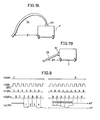
- the cable 25 for exchanging signals with the control apparatus in the scanner portion 1′ is taken out from a projecting area 24 provided on the upper portion of an upper cabinet of the scanner portion 1′ from the following reason. Namely, as is apparent from the comparison of Figs. 7A and 7B, the distance l1 (Fig. 7A) required for connecting the cable 25 to another apparatus or to the running assisting plate when the cable is taken out from the projection 24 on the upper portion of the scanner portion 1′ in this embodiment of the present invention can be made far longer than the distance l2 (Fig. 7B) required for connecting the cable 25 to an apparatus such as the running assisting plate when the cable 25 is taken out from the side portion of the scanner portion 1′ through a taking area 24′. Consequently, bad influences to the running of the scanner portion 1′ derived from friction of the cable 25 or the like can be removed, and therefore the scanner portion 1′ can be moved more stably.
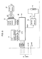
- Fig. 8 is a block diagram showing an electrical structure of the scanner portion in the self-running type scanner in accordance with one embodiment of the present invention. Referring to Fig. 9, portions corresponding the structure of Fig. 3 are designated by the same reference numerals.
- the scanner portion comprises a CPU 50 formed of one chip, for example, for controlling various operations of the scanner portion.
- the CPU 50 outputs control signals ⁇ T , ⁇ 1, ⁇ 2, ⁇ R and ⁇ SH for applying operation timing of the one dimensional image sensor 13 consisting of, for example, CCDs to the image sensor 13 and receives image information 0 from the image sensor 13 at an A/D terminal thereof.
- the signal ⁇ T gives the timing for starting scanning of the image sensor 13. Namely, in response to the signal ⁇ T , the information of the CCD cells in the image sensor 13 is transferred to an analog shift register (not shown).
- Clock signals ⁇ 1 and ⁇ 2 are two phase complementary clock signals which do not overlap with each other, applying data transfer timing in the analog shift register.
- the CCD cell information of the image sensor 13 is successively transmitted through the analog shift register in response to the clock signals ⁇ 1 and ⁇ 2.
- the signal ⁇ R applies data output timing of the image sensor 13.
- the information of the image sensor 13 is successively outputted in response to the signal ⁇ R .
- the signal ⁇ SH is a signal for applying timing of sampling/holding the CCD cell information outputted in response to the signal ⁇ R .
- each piece of information from the CCD cell is sampled/held in response to the signal ⁇ SH to be outputted as the output signal 0 from the image sensor 13.
- Fig. 9 shows a case in which the image sensor 13 comprises 576 CCD cells, as an example.
- the structure comprising 576 CCD cells is determined to satisfy the following conditions. Namely, assuming that the reading area (area B in Fig. 4) of the scanner portion has the width of 64 mm and the length of 100 mm, the image of the object is resolved with the resolution of 8 mm in Y and X directions, respectively, by the scanner portion.
- the CPU 50 receives +5V through the cable 25 as the operational power supply.
- the CPU 50 outputs a STATE signal indicative of the reading of image information of the object, a signal SYNC indicative of the starting position of 1 line of the image information to be transmitted, the image information DATA from the CCD and the clock signal CLOCK for giving the data transmitting timing, in order to transmit the output from the image sensor 13 to external apparatuses (host computer, image processing apparatus and so on).
- the image information DATA outputted from the CPU 50 comprises only the image information of the object read in the effective reading area (the area B in Fig. 4), and not the image information of the white area 35 or the like provided on the running assisting plate 23.
- the timing relation between the signals outputted from the CPU 50 is shown in Fig. 10.
- a pulse motor driver 51 for driving the pulse motor 46 is provided for driving the running of the scanner portion 1′.
- the pulse motor driver 51 receives motor rotation instructing signals ⁇ A ⁇ , ⁇ B , and ⁇ B ⁇ from the CPU 50, amplifies the level thereof to be sufficient for driving the pulse motor 46 and transmits control signals ⁇ A , ⁇ A ⁇ , ⁇ B and ⁇ B ⁇ as well as the supply voltage +5V to the pulse motor 64.
- a two-phase-on type four phase pulse motor is used as the pulse motor 66, and it is stopped or rotated in either the negative direction or the positive direction by the combination of the signal levels of the control signals ⁇ A , ⁇ A ⁇ , ⁇ B and ⁇ B ⁇ .
- the pulse motor 46 makes the scanner portion 1′ run by 1/8 mm per 1 step in response to the control signal from the pulse motor driver 51.
- a lighting apparatus 52 is provided for lighting the illuminating light source 10, which apparatus applies complementary high voltage signals V R and V L to the illuminating light source 10 in response to a lighting instructing signal FLON from the CPU 50.
- the illuminating light source 10 comprises, for example, a fluorescent lamp which is turned on by the application of the complementary lighting signals V R and V L , which in turn sets the lamp in the same state as is connected to an alternating power supply.
- the CPU 50 has a memory device consisting of a RAM (Random Access Memory) as will be described later (see Fig. 13).
- the slice level which is the reference for determining whether the read image information is white or black is stored in the memory device, and the CPU determines whether the read image information is white or black dependent on the stored slice level and outputs the result as the output data DATA through the cable 25.
- the operation of the self-running type scanner in accordance with one embodiment of the present invention will be described in the following with reference to Figs. 11 to 13.
- the scanner portion 1′ is set such that the reading line (the area illuminated by the light from the illuminating light source 10, and the reflected light from the object reaches the image sensor 13 to be read, that is, 1 line in the X direction in Fig. 4) is at an appropriate position of the light transmitting area 34 of the running assisting plate 23.
- the CPU 50 applies various controlling signals to the image sensor 13 to read image information from the image sensor 13.
- the image sensor comprises 576 CCD cells and the CPU 50 receives CCD cell outputs from the first to 576th cells (the number of the CCD cells increases from the side of the white area 35 to the + direction in the X direction shown in Fig. 4) to A/D convert (analog-digital convert) the same.
- A/D convert analog-digital convert
- the CPU 50 sets the output to 255 and when the output is 0 V, the CPU 50 set the output to 0.
- the output value between 0 to 5 V is A/D converted stepwise, each step being about 19.6 mV.
- the range from 0 V to 5 V is divided into 256 levels, and the CCD cell output is represented by one of these levels.
- the 256 levels are represented in 8 bit binary number. Since the illuminating light source 10 does not emit light, the resultant 576 CCD cell outputs after the AD conversion are all at about 4 V, which corresponds a black level.
- the black level data are stored in the memory addresses 704 to 1279 of a third RAM area of the memory device included in the CPU 50, as VBL1, VBL2,...VBL576.
- the lighting instruction signal FLON is generated and the lighting apparatus 52 is activated to turn on the illuminating light source 10.
- the CPU 50 checks the outputs from the first to 64th CCD cells out of the outputs from the image sensor 13.
- the white level (no more than 3 V) of about 4 mm in width corresponding to the white area 35 can be found in the outputs from the first to 64th CCD cells.
- the CPU 50 determines that the scanner portion 1′ is not positioned at the reading start position, and it outputs a control signal to the pulse motor driver 51 of the scanner portion 1′ to drive the pulse motor 46, so that the scanner portion 1′ is moved in the positive direction in the Y direction stepwise, each step being 1/8 mm.
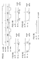
- the scanner portion 1′ As the scanner portion 1′ runs, the X direction timing mark 37 is detected at a certain time point, and a black level (no less than 3.5 V) having the width of about 1 mm appears as shown in Fig. 11B in the outputs from the first to 32nd CCD cells. After the detection of the X direction timing mark 37, the scanner portion 1′ is further moved in the positive direction in the Y direction by the step of 1/8 mm. Consequently, the X direction timing mark 37 disappears and the white level of about 4 mm in width as shown in Fig. 11A is again found in the outputs from the first to 32nd CCD cells. The scanner portion 1′ continues to run at the step of 1/8 mm.
- the image sensor 13 comes to scan the white area 35 extending in the X direction. Consequently, the outputs from the 576 CCD cells of the image sensor 13 all become white level, so that the output waveform as shown in Fig. 11D is applied to the CPU 50.
- the scanner portion 1′ is further moved from this point to the + direction in the Y direction by 10 mm to be stopped there. Therefore, the area detected by the image sensor 13 corresponds to the black area D of the running assisting plate 23 (Fig. 11E).
- the scanner portion 1′ starts running in the - direction of Y direction under the control of the CPU 50.
- the black level having the width of about 2 mm is found in outputs from the first to 32nd CCD cells included in the image sensor 13.
- the CPU 50 stops the running of the scanner portion 1′.
- the output signal of the image sensor 13 at this point have such waveform as shown in Fig. 11C.
- the CPU 50 AD converts the outputs from the first to 576th CCD cells out of the CCD cell outputs from the image sensor 13, calculates average values with the signal levels which have been stored in the second RAM area of the memory device in the CPU 50, and again stores the average values to the original addresses. More specifically, assuming that the signal values of the CCD cells after AD conversion are VOW′1, VOW′2,... VOW′575 and VOW′576, the signal values VOW1, VOW2,... VOW576 which have been stored in the second RAM area are read to provide average output of each of the cells. Namely, the values (VOW1 + VOW′1)/2, (VOW2 + VOW′2)/2, ...
- VOW576 + VOW′576)/2 are calculated.
- the average values are written in the corresponding addresses from the memory address 128 to 703 as the new white level reference values VOW1, VOW2, ... VOW576. Since the Y direction timing mark 36 has been detected, there is an output signal indicative of the black level out of the output signals from the first to 32nd CCD cells. However, only the 65th to 576th CCD cell outputs are used as the information from the effective area for reading images of the object, that level has no influence on the actual reading of the image information of the object.
- the scanner portion 1′ runs in the - direction in the Y direction only by a step of 1/8 mm under the control of the CPU 50.
- the waveform v0 of the output signal from the image sensor 13 at this time point become as shown in Fig. 11c as in the above described case, since the width of the Y direction timing mark 36 is about 1 mm.
- the CCD cell outputs from the image sensor 13 are AD converted in the similar manner as described above, and the respective numerical values are provided as VOW1 ⁇ , VOW ⁇ 2,... VOW ⁇ 575 and VOW ⁇ 576.
- the average value between them and the white level reference values VOW1, VOW2, ... VOW3... VOW576 which have been calculated by the previous averaging operation are calculated.
- the values provided in this manner are stored as the new reference level values VOW1, VOW2, ... VOW576 in the memory addresses 128 to 703 in the second RAM area of the memory device in the CPU 50.
- the reference values VO1, VO2, VOW3,... VOW575 and VOW 576 stored in the second RAM area of the memory addresses 128 to 703 in the memory device of the CPU 50 represent the average values of the levels in a rectangular area having the width of 1 mm and the length of 72 mm, which corresponds to the Y direction timing mark 36 in the white area having the width of 4 mm extending in the Y direction shown in Fig. 4. Out of these, the outputs from the 65th to the 576th CCD cells are used as the CCD cell outputs corresponding to the length of 64 mm of the reading area.
- the average value of the white level in this area is used as the white level reference value in the actual reading of the image of the object.
- the output from the first CCD cell in 8 times of scanning of the white area that is, P′1, P2 1, ...P81 is averaged and the average value is stored in the memory address 128 as the value VOW1.
- the average value VOW2 of the outputs P′2, P2 2, ...P8 2 from the second CCD cell is stored in the memory address 129.
- the average value VOW512 of the outputs P′576, P2576, ... P8576 from the 576th CCD cell is stored in the memory address 703.
- the average value of the CCD cell outputs over several lines (8 lines in the embodiment) is used as the reference value of the white level in order to reduce the influence of dust, unevenness of color and the like.
- the CPU 50 provides a slice level which becomes the reference for determining white or black in detecting image information, by using the stored reference values VOWi and VBLi.
- the calculated slice levels are respectively stored in a fourth RAM area, i.e., the memory addresses 1280 to 1855 of the memory device.
- the scanner portion 1′ runs in the - direction of the Y direction to a point where the waveform of the output signal from the image sensor 13 changes from that of Fig. 11C to that of Fig. 11D, under the control of the CPU 50.
- the fact that the CCD cell output from the image sensor 13 has such a waveform as shown Fig. 11D means that the areas scanned by the image sensor 13 are all white areas.
- the CPU 50 clears the Y address in the memory address 1857 of the memory device to "0" in response.
- the CPU 50 increments Y address of the memory address 18577 by "1".
- the scanner portion 1′ continues to run, and when the waveform of the output signal from the image sensor 13 changes from that shown in Fig. 11D to that shown in Fig. 11B, it means that the image sensor scans the X direction timing mark 37.
- the CPU 50 stores in the X address in the memory address 1856 of the memory device, the number value of the CCD cell having the largest number outputting black label (no less than 3.5 V) out of the first to 32nd CCD cells of the image sensor 13. Now, if the 9th CCD cell to l6th CCD cell provide black level, the value to be stored in the memory address 1856 is 16, for example.
- the CPU 50 sets the signal STATE to an active state, that is, "1", which signal indicates that the image reading operation is being carried out.
- the CPU 50 outputs the signal SYNC indicative of the start of 1 line of the data, the clock signal CLOCK giving the transferring timing of the data, and the data DATA read from the image sensor 13 through the cable 25.
- the image data DATA outputted from the CPU will be described.
- all of the 576 CCD cell outputs are used in detecting the white level for providing the slice level.
- the outputs from the CCD cells in the area from which the white level is surely detected may be used.
- the scanner portion and a driving portion for driving the scanner portion are integrally provided in a self-running type scanner, so that the number of parts as well as the time required for the assembly can be reduced, enabling provision of an inexpensive self-running type scanner capable of surely providing image information.
- a Y direction timing mark and a X direction timing mark are provided on a running assisting plate, it is adapted such that the position for starting actual image reading of the object is determined in accordance with the timing marks and the data of several lines in a white area provided on the running assisting plate are used to provide reference for determining whether the read information of the object is white or black, influences of an unevenness in color in the white area, the dust, degradation of illuminating light source and the like can be removed and the image information of the object can be surely provided.
Landscapes
- Engineering & Computer Science (AREA)
- Multimedia (AREA)
- Signal Processing (AREA)
- Facsimile Scanning Arrangements (AREA)
- Image Input (AREA)
Applications Claiming Priority (2)
| Application Number | Priority Date | Filing Date | Title |
|---|---|---|---|
| JP230791/88 | 1988-09-14 | ||
| JP63230791A JPH0279555A (ja) | 1988-09-14 | 1988-09-14 | 自走式スキャナ |
Publications (3)
| Publication Number | Publication Date |
|---|---|
| EP0359568A2 true EP0359568A2 (de) | 1990-03-21 |
| EP0359568A3 EP0359568A3 (de) | 1991-07-17 |
| EP0359568B1 EP0359568B1 (de) | 1995-07-12 |
Family
ID=16913323
Family Applications (1)
| Application Number | Title | Priority Date | Filing Date |
|---|---|---|---|
| EP89309353A Expired - Lifetime EP0359568B1 (de) | 1988-09-14 | 1989-09-14 | Selbstlaufender Abtaster zum optischen Lesen von Bildern |
Country Status (5)
| Country | Link |
|---|---|
| US (1) | US5168377A (de) |
| EP (1) | EP0359568B1 (de) |
| JP (1) | JPH0279555A (de) |
| CA (1) | CA1325062C (de) |
| DE (1) | DE68923414T2 (de) |
Cited By (5)
| Publication number | Priority date | Publication date | Assignee | Title |
|---|---|---|---|---|
| EP0503165A1 (de) * | 1991-03-12 | 1992-09-16 | Agfa-Gevaert N.V. | Optisches Abtastgerät |
| EP0663757A3 (de) * | 1994-01-14 | 1996-03-13 | Miles Inc | Abtastgerät mit einem selbstfahrenden und geradlinig bewegenden Wagen. |
| US5778277A (en) * | 1996-10-25 | 1998-07-07 | Xerox Corporation | Tilted scan rail |
| EP0751668A3 (de) * | 1995-06-29 | 1999-08-25 | Agfa Corporation | Antriebsystem für Abtaster mit Wagenaufhängung mit minimiertem Rotationsfehler |
| WO2007012802A1 (en) * | 2005-07-25 | 2007-02-01 | Thillainayagam Vidhya Rajeswar | The multifunctional mobile scanning device |
Families Citing this family (10)
| Publication number | Priority date | Publication date | Assignee | Title |
|---|---|---|---|---|
| US5293257A (en) * | 1990-12-11 | 1994-03-08 | Katsuya Masao | Mobile size independent image input/output apparatus and plate |
| US5282081A (en) * | 1992-08-19 | 1994-01-25 | Must Systems, Inc. | Dual reflecting type and transmitting type scanner |
| US5446559A (en) * | 1992-10-05 | 1995-08-29 | Hewlett-Packard Company | Method and apparatus for scanning and printing |
| JPH08237440A (ja) * | 1995-02-24 | 1996-09-13 | Nikon Corp | 画像入力装置の照明装置及び画像入力装置 |
| JPH08331327A (ja) * | 1995-06-01 | 1996-12-13 | Brother Ind Ltd | 原稿読取り装置 |
| EP0996922A4 (de) * | 1997-07-23 | 2001-01-17 | Xros Inc | Verbesserter dokumentenscanner mit handgriff |
| KR100579835B1 (ko) * | 2004-04-16 | 2006-05-15 | 삼성전자주식회사 | 이미지 센서의 구동 제어방법 |
| US7558437B2 (en) * | 2005-03-15 | 2009-07-07 | Kabushiki Kaisha Toshiba | Method and apparatus for image processing |
| US9906664B2 (en) | 2015-12-30 | 2018-02-27 | Kodak Alaris Inc. | Mobile autonomous scalable scanner system |
| US9936089B2 (en) | 2015-12-30 | 2018-04-03 | Kodak Alaris Inc. | Mobile autonomous scalable scanner system |
Family Cites Families (11)
| Publication number | Priority date | Publication date | Assignee | Title |
|---|---|---|---|---|
| US4439790A (en) * | 1981-01-23 | 1984-03-27 | Canon Kabushiki Kaisha | Image forming apparatus |
| JPS5834125A (ja) * | 1981-08-25 | 1983-02-28 | Nippon Steel Corp | 溶鋼の清浄化方法 |
| US4486786A (en) * | 1981-09-08 | 1984-12-04 | Canon Kabushiki Kaisha | Original reading device |
| JPS58111476A (ja) * | 1981-12-25 | 1983-07-02 | Fuji Photo Film Co Ltd | 携行用複写装置 |
| JPS6143328A (ja) * | 1984-08-07 | 1986-03-01 | Nippon Denki Kaigai Shijiyou Kaihatsu Kk | 光デイジタイザ |
| JPS61232764A (ja) * | 1985-04-06 | 1986-10-17 | Ricoh Co Ltd | リニア型原稿読取り装置 |
| DE3677584D1 (de) * | 1985-12-27 | 1991-03-28 | Oki Electric Ind Co Ltd | Elektronische schreibtafel. |
| JPS62293384A (ja) * | 1986-06-11 | 1987-12-19 | Toshiba Corp | 画像入力装置 |
| EP0257747A3 (de) * | 1986-07-15 | 1990-01-17 | OIS Optical Imaging Systems, Inc. | Photoelektrische Anordnung zur Abtastung von grossen nicht-ebenen bildenthaltenden Flächen |
| DE3703217A1 (de) * | 1987-01-30 | 1988-08-11 | Siemens Ag | Optische abtasteinrichtung |
| JPH0683343B2 (ja) * | 1987-11-10 | 1994-10-19 | 東京電気株式会社 | 光学式画像読取装置 |
-
1988
- 1988-09-14 JP JP63230791A patent/JPH0279555A/ja active Pending
-
1989
- 1989-09-12 US US07/406,306 patent/US5168377A/en not_active Expired - Lifetime
- 1989-09-13 CA CA000611307A patent/CA1325062C/en not_active Expired - Fee Related
- 1989-09-14 DE DE68923414T patent/DE68923414T2/de not_active Expired - Fee Related
- 1989-09-14 EP EP89309353A patent/EP0359568B1/de not_active Expired - Lifetime
Cited By (5)
| Publication number | Priority date | Publication date | Assignee | Title |
|---|---|---|---|---|
| EP0503165A1 (de) * | 1991-03-12 | 1992-09-16 | Agfa-Gevaert N.V. | Optisches Abtastgerät |
| EP0663757A3 (de) * | 1994-01-14 | 1996-03-13 | Miles Inc | Abtastgerät mit einem selbstfahrenden und geradlinig bewegenden Wagen. |
| EP0751668A3 (de) * | 1995-06-29 | 1999-08-25 | Agfa Corporation | Antriebsystem für Abtaster mit Wagenaufhängung mit minimiertem Rotationsfehler |
| US5778277A (en) * | 1996-10-25 | 1998-07-07 | Xerox Corporation | Tilted scan rail |
| WO2007012802A1 (en) * | 2005-07-25 | 2007-02-01 | Thillainayagam Vidhya Rajeswar | The multifunctional mobile scanning device |
Also Published As
| Publication number | Publication date |
|---|---|
| DE68923414T2 (de) | 1996-02-01 |
| EP0359568B1 (de) | 1995-07-12 |
| US5168377A (en) | 1992-12-01 |
| EP0359568A3 (de) | 1991-07-17 |
| CA1325062C (en) | 1993-12-07 |
| DE68923414D1 (de) | 1995-08-17 |
| JPH0279555A (ja) | 1990-03-20 |
Similar Documents
| Publication | Publication Date | Title |
|---|---|---|
| US5168377A (en) | Self-running scanner for optically reading images | |
| US6270013B1 (en) | Hand-holdable optical scanner particularly useful as electronic translator | |
| US4684998A (en) | Image reader suitable for manual scanning | |
| EP0439357A2 (de) | Verfahren und Vorrichtung zur Ausstattung eines Dokumentenlesers mit Sensorkompensation | |
| WO1997001827A1 (en) | Hand-held scanner with rotary position detector | |
| EP0177461B1 (de) | Gerät zur Abtastung von auf einem Substrat dargestellter graphischer Information | |
| JP2889080B2 (ja) | スキャナ | |
| US5481371A (en) | Image reading device having variable internal synronization setting control | |
| US4891711A (en) | Document reader for a digital copier | |
| JPH049975A (ja) | 光書込み装置 | |
| JPH10294831A (ja) | 初期位置センサ | |
| JPH0416526Y2 (de) | ||
| JPH0416969A (ja) | 光書込み装置 | |
| JP2910600B2 (ja) | 画像入力装置 | |
| JPH04213960A (ja) | 文書スキャナにおける文書基準化コーナーの位置決め方法及びその装置 | |
| JPH0336351B2 (de) | ||
| JP2540818B2 (ja) | イメ−ジセンサ出力の2値化回路 | |
| JPH01105970A (ja) | 電子写真式リーダ・プリンタ | |
| JPH05199375A (ja) | 複写機光学系の速度制御装置 | |
| JP2721759B2 (ja) | 画像入力装置 | |
| JPH01105271A (ja) | 電子写真式リーダ・プリンタ | |
| JPS62198255A (ja) | 画像読取装置 | |
| JPS60160263A (ja) | 情報表示装置 | |
| JPS6282872A (ja) | 原稿読取装置 | |
| JPS61111062A (ja) | 情報処理装置 |
Legal Events
| Date | Code | Title | Description |
|---|---|---|---|
| PUAI | Public reference made under article 153(3) epc to a published international application that has entered the european phase |
Free format text: ORIGINAL CODE: 0009012 |
|
| AK | Designated contracting states |
Kind code of ref document: A2 Designated state(s): DE FR GB |
|
| 17P | Request for examination filed |
Effective date: 19901214 |
|
| PUAL | Search report despatched |
Free format text: ORIGINAL CODE: 0009013 |
|
| AK | Designated contracting states |
Kind code of ref document: A3 Designated state(s): DE FR GB |
|
| 17Q | First examination report despatched |
Effective date: 19931110 |
|
| GRAA | (expected) grant |
Free format text: ORIGINAL CODE: 0009210 |
|
| AK | Designated contracting states |
Kind code of ref document: B1 Designated state(s): DE FR GB |
|
| REF | Corresponds to: |
Ref document number: 68923414 Country of ref document: DE Date of ref document: 19950817 |
|
| ET | Fr: translation filed | ||
| PLBE | No opposition filed within time limit |
Free format text: ORIGINAL CODE: 0009261 |
|
| STAA | Information on the status of an ep patent application or granted ep patent |
Free format text: STATUS: NO OPPOSITION FILED WITHIN TIME LIMIT |
|
| 26N | No opposition filed | ||
| REG | Reference to a national code |
Ref country code: GB Ref legal event code: IF02 |
|
| PGFP | Annual fee paid to national office [announced via postgrant information from national office to epo] |
Ref country code: GB Payment date: 20040908 Year of fee payment: 16 Ref country code: FR Payment date: 20040908 Year of fee payment: 16 |
|
| PGFP | Annual fee paid to national office [announced via postgrant information from national office to epo] |
Ref country code: DE Payment date: 20040909 Year of fee payment: 16 |
|
| PG25 | Lapsed in a contracting state [announced via postgrant information from national office to epo] |
Ref country code: GB Free format text: LAPSE BECAUSE OF NON-PAYMENT OF DUE FEES Effective date: 20050914 |
|
| PG25 | Lapsed in a contracting state [announced via postgrant information from national office to epo] |
Ref country code: DE Free format text: LAPSE BECAUSE OF NON-PAYMENT OF DUE FEES Effective date: 20060401 |
|
| GBPC | Gb: european patent ceased through non-payment of renewal fee |
Effective date: 20050914 |
|
| PG25 | Lapsed in a contracting state [announced via postgrant information from national office to epo] |
Ref country code: FR Free format text: LAPSE BECAUSE OF NON-PAYMENT OF DUE FEES Effective date: 20060531 |
|
| REG | Reference to a national code |
Ref country code: FR Ref legal event code: ST Effective date: 20060531 |