EP0360136A1 - Verfahren und Vorrichtung zum Aufschneiden und Öffnen von rechteckigen Verpackungen - Google Patents
Verfahren und Vorrichtung zum Aufschneiden und Öffnen von rechteckigen Verpackungen Download PDFInfo
- Publication number
- EP0360136A1 EP0360136A1 EP89116895A EP89116895A EP0360136A1 EP 0360136 A1 EP0360136 A1 EP 0360136A1 EP 89116895 A EP89116895 A EP 89116895A EP 89116895 A EP89116895 A EP 89116895A EP 0360136 A1 EP0360136 A1 EP 0360136A1
- Authority
- EP
- European Patent Office
- Prior art keywords
- cutting
- packaging material
- package
- platform
- planes
- Prior art date
- Legal status (The legal status is an assumption and is not a legal conclusion. Google has not performed a legal analysis and makes no representation as to the accuracy of the status listed.)
- Withdrawn
Links
Images








Classifications
-
- B—PERFORMING OPERATIONS; TRANSPORTING
- B65—CONVEYING; PACKING; STORING; HANDLING THIN OR FILAMENTARY MATERIAL
- B65B—MACHINES, APPARATUS OR DEVICES FOR, OR METHODS OF, PACKAGING ARTICLES OR MATERIALS; UNPACKING
- B65B69/00—Unpacking of articles or materials, not otherwise provided for
- B65B69/0033—Unpacking of articles or materials, not otherwise provided for by cutting
Definitions
- the invention relates to a method and a device for cutting a rectangular package covered with packaging material at a prescribed position and opening it.
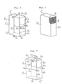
- packaging container blanks are flatly folded as shown in Fig. 20 (A), and combined to a bundle whose outside is covered with packaging material (B) (as shown in Fig. 1) for easy storage and handling.
- the packaging material (B) covering its outside needs to be cut and opened. Hitherto, the operations were carried out manually or by the method and device described in the published, unexamined Japanese Patent Application No. 271828.
- the main object of the invention is to provide a cutting and opening method and a device for a rectangular package, by which any type of package regardless of the type of packaged matters or the strength of the packaging material can be automatically cut and opened.
- a space between the packaging material and the packaged matters on the two mutually opposing planes of the rectangular package covered with packaging material thereafter, the packaging material is cut on those planes from one edge to the other in the direction of height or width, and the packaging material is cut on the above mentioned two planes from one of the two edges other than the edges passing the starting point and the end point of the cutting line.
- the packaging material is cut so as to connect the two cutting lines, and thereafter the packaging material is opened from each cut area on the three planes provided with cutting lines.
- a backplate is inserted via a slit made by cutting the packaging material on the two mutually opposing planes of the rectangular package from one edge to the other, and the packaging material on these planes is cut on top of the backplate.
- the locations of the cutting lines to be provided on the two mutually opposing planes from one edge to the other are varied with respect to the datum plane to be provided with a cutting line and adjacent to the two planes.
- the device comprises a platform on which a package covered with packaging material is placed; means to form a space between the packaging material and the packaged matters on the two mutually opposing planes of the package on the platform; a first pair of cutting blades for cutting the packaging material from one edge to the other on a position where the space is formed between the packaging material and the packaged matters using the above means; a second pair of cutting blades for cutting the packaging material from one of the two edges other than the edges passing the starting point and the end point of the two edges cut by the above first pair of cutting blades to the above mentioned cutting lines; means to form a space between the packaging material and the packaged matters on the plane having two edges passing the ends of the two cutting lines cut by the above second pair of cutting blades; a further cutting blade for cutting the packaging material in such a manner that the two cutting lines on this plane are connected; and a device to open the packaging material from each cut area on the three planes provided with cutting lines.
- a pair of holders for holding a part of the two mutually opposing planes of the rectangular package placed on the platform from both sides, which are provided on the side of the platform.
- a pair of backplates is provided that can move parallel to the two mutually opposing planes of the rectangular package placed on the platform and can be inserted from slits on these two planes made by cutting the packaging material from one edge to the other.
- the platform is positioned in relation to a cylinder so that the position of the platform can be varied with respect to the plane to be provided with a cutting line and adjacent to the two planes of the package to be cut from one edge to the other according to the size of each package.
- a pair of cutting blades is also applied on the two mutually opposing planes in order to cut them from one edge to the other, as well as a pair of holders, and a pair of means to form a space between the packaging material and the packaged matters on the two planes cut from one edge to the other of the package are related to a cylinder so that their operating positions can all be varied according to the sizes of the rectangular packages similar to the platform.
- a backboard that positions the back plane of the package with respect to the platform be located at the back of the platform, and the backboard be positioned in relation to a cylinder so that the position of the said backboard can be varied with respect to the plane to be provided with cutting lines and adjacent to the two mutually opposing planes cut from one edge to the other according to the size of the package to be placed on the platform.
- the activation positions of the platform, the first pair of cutting blades, the pair of holders, the pair of means to form a space between the packaging material and the packaged matters on the two planes of the package that are cut from one edge to the other, and the backboard are related to the cylinder so that they can all be varied with respect to the datum plane of the package, and their positions are chosen according to the depth of the package if necessary.
- the packages are preferably carried in a storage box to the prescribed position on the side of the platform.
- the packaged objects can be cut non-damaged in either case. Also according to the embodiment described in Claim 3, there is no need to implement a means to form a space between the packaging material and the packaged objects on the plane adjacent to the two mutually opposing planes.
- lengthwise and widthwise cutting positions on the two mutually opposing planes of the rectangular package are different according to the size of the package. Therefore, even when cutting different-sized packages, the packaging material can be always be opened.
- the rectangular package does not move on the platform at hazard, eliminating malfunctions such as undesired dislocation of the cutting position or damage to the packaged matters.
- a backplate can be used as a support and a cutting blade can be run on the packaging material from outside, eliminating the possibility of damaging the packaged objects.
- the location of the platform with respect to the datum position can be freely varied according to the size of the package. Therefore, even when handling packages of different sizes, they can all be placed on a single platform.
- the packaging material is cutted in the direction of height or width at the supposedly optimal positions on the two mutually opposing planes even when the packages are different in sizes.
- a pair of cutting blades can be placed in the supposedly optimal positions according to the size of the package when cutting the package on the platform, render ideal cutting and opening operations possible even when packages are different in size.
- a package prior to be placed on the platform can be placed at a prescribed position, render ideal cutting and opening operations possible according to the size of the package even when packages are different in sizes.
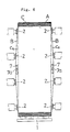
- a package cut by the method according to the invention is shown in Fig. 2 and and Fig. 4.
- cutting lines c1 and c1 are running longitudinally from one edge to the other on two mutually opposing planes C1 and C1, and on each plane, a cutting line c6 is provided between the above mentioned cutting line c1 and the edge c5, which is one of two edges c4 and c5 other than edges c2 and c3 passing the starting point s1 and the end point s2 on the cutting line c1, and on the plane C2 adjacent to C1, C1 each having two edges c5, c5 passing points s3, s3 of the two cutting lines c6, c6, a cutting line c7 connecting these two cutting lines is provided.
- the package can be opened as shown in Fig. 3 (g).
- the two mutually opposing planes C1 and C1 are cut longitudinally from one edge to the other end, and a cutting line c7 is provided on the plane C2
- spaces c8 and c9 are formed on the planes C1, C2 and C3 between the packaging material and the packaged objects or matters as shown in Fig. 5 and Fig. 6, preventing damage to the packaged objects even if the cutting blade is applied to the packaging material B.
- cutting lines c11 and c11 are running horizontally from one edge to the other on two mutually opposing planes C1 and C1, and on each plane, a cutting line c61 is provided between the above mentioned cutting line c11 and the edge c2, which is one of two edges c2 and c3 other than edges c4 and c5 passing the starting point s11 and the end point s21 on the cutting'line c11, and on the plane C3 adjacent to C1, C1 each having two edges c2 and c3 passing points s31, s31 of the two cutting lines c61, c61, a cutting line c71 connecting these two cutting lines is provided.
- the packaging material on the three planes C1, C1 and C3 on which cutting lines c11, c11, c61, c61 and c71 are provided is cut and opened at each cutting line, the package can be opened, as opposed to the case in Fig. 2, in a fashion that the package shown in Fig. 3 (g) is in the horizontal position.
- a cutting line c11 is provided as shown in Fig. 4 and a space formed between the packaging material and the packaged objects on each of the two mutually opposing planes C1, C1
- the packaging material would be like the one shown in Fig. 3 (d) positioned horizontally.
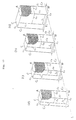
- a ruler-like plate 7 could be inserted from the slit c1 as shown in Fig. 3 (e) and Fig. 5 to cut the packaging material on top of it to avoid damaging the edges of the packaged objects.
- a cutting line c61 in Fig. 4 shall also be provided in the same fashion.
- formation of a space c9 between the packaging material and the packaged objects requires no extra means because the plate 7 presses the packaging material outward.
- a rectangular package C covered with packaging material B as shown in Fig. 1 is placed on a platform 1 as shown in chain line in Fig. 19.
- a space c8 shown in Fig. 6 is formed between the packaging materials B, B and the packaged objects on these two planes C1, C1.
- a pair of cutting blades 3, 3 is pressed and run on the packaging material on the two planes C1, C1, areas shown by c1, c1 on the two planes in Fig.
- a cutting line is provided in the direction shown by c11 in Fig. 4 on the two mutually opposing planes C1, C1, means to form a space between the packaging material and the packaged objects on the two planes C1, C1 are preferably placed in the latitudinal direction, in which case the pair of cutting blades 3, 3 to cut this packaging material shall also run in the latitudinal direction.
- a pair of cutting blades 4,4 shown in Fig. 8 is applied in the latitudinal direction to the packaging material that is already cut from one edge to the other by the pair of cutting blades 3 and 3.
- the packaging material cut from one edge to the other by the pair of cutting blades 4, 4 is then provided with a cutting line shown by c6 in Fig. 2.
- the pair of cutting blades 4, 4 is arranged perpendicularly, as opposed to the example shown in the figure, and run vertically.
- a means to form a space between the packaging material and the packaged objects on the plane C2 having two edges c5, c5 passing points s3, s3 of the two cutting lines c6 and c6, is activated.
- a cutting blade shown by 5 in Fig. 8 is pressed on the packaging material on the plane C2 and run latitudinally.
- This provides the packaging material on the plane C2 with a cutting line shown by c7 in Fig. 2.
- the cutting blade 5 is arranged perpendicular, as opposed to the example in the figure, and run latitudinally.
- a device is activated to open the package along the cutting lines c1, c1 and c6, c6 and c7 on the three planes C1, C1 and C2 respectively, and a package C′ cut as shown in Fig. 2 can be opened as shown in Fig. 3 (g).
- the package can be opened in the manner that Fig. 3 (g) is in the horizontal position.
- these two planes C1, C1 can be held by a pair of holders 6, 6 to prevent unnecessary movement of the package during the operation of cutting on the platform 1.
- the pair of holders 6, 6 shall operate on the two mutually opposing planes C1, C1 as shown in Fig. 3 (c), and when they are cut as shown in Fig. 4, they shall operate on the two opposing planes C1, C1 in the fashion that Fig. 3 (c) is in the horizontal position.
- a pair of cutting blades 3, 3 applied on the two mutually opposing planes that are cut from one edge to the other, a pair of holders 6, 6, and means for forming a space between the packaging material and the packaged objects on the aforementioned two planes C1, C1, can be varied with respect to the planes C2, C3 adjacent to the two planes C1, C1 to be cut from one edge to the other and on which cutting lines c7, c71 are to be provided, according to the size of the package by operating each cylinder according to the size of the package. This will now be described with reference to Fig. 17 (a) to (c).
- a plane C2 to be provided with a cutting line c7 is placed on one datum line L in the case of three packages of different sizes (depth, length) L1 to L3, if a pair of cutting blades 3, 3 for providing a cutting line c1 on each of the two mutually opposing planes C1 and C1 are positioned at distances of l1, l2, and l3 respectively from each datum plane C2 according to the size (depth, length) of each package, for example, a cutting line c1 can be provided at distances of l1, l2 and l3 respectively from each datum plane C2 on each of the two mutually opposing planes C1, C1.
- the operating positions of the pair of holders 6, 6 and the means for forming a space between the packaging material and the packaged objects on the two planes C1, C1 can also be varied as in the case of the pair of cutting blades 3, 3, according to the size (depth, length) of the package.
- the position of the backboard 8 located at the back of the platform 1 is varied with respect to the datum line L according to the size (depth, length) of the rectangular package as shown in Fig. 16 (a) to (c). This way, the package to be placed on the platform 1 can be placed at its prescribed position according to its size (depth, length).
- the activation positions, with respect to the package, of the platform 1, a pair of cutting blades 3, 3, a pair of holders 6, 6, means for forming a space between the packaging material on the two planes C1, C1 of the package that are cut from one edge to the other and the packaged objects, and the backboard 8, are selected appropriately according to the size (depth, length) of the package.
- a package of any size can be provided with a cutting line of a prescribed direction on a prescribed plane of the rectangular package by using a single device as shown in Fig. 2.
- a single device as shown in Fig. 2.
- the packaged objects are flattened packing container blanks as shown in Fig. 20, wherein is shown the way by which multiple blanks A are bundled and covered with packaging material B on the outside as shown in Fig. 1 and such a rectangular package C is cut and opened.
- the packaging material B of the package C is shown in Fig. 1 is cut as shown in Fig. 2 and opened as shown in Fig. 3 (g).
- the method according to the invention can also be applied to cutting and opening the rectangular package C as shown in Fig. 4.
- the biggest difference between the cutting as shown in Fig. 2 and cutting as shown in Fig. 4, is that while in the case of Fig. 2, the cutting direction of the packaging material on the two mutually opposing planes of the rectangular package C from one edge to the other is in the vertical direction (in the direction of height), in the case of Fig. 4, it is in the horizontal direction (in the direction of width).
- the position or direction at or in which a space between the packaged objects and the packaging material B is formed, or the direction of cutting lines c6, c6 and c61, c61 on the two mutually opposing planes C1, C1, the position of the planes C2, C3 each incorporating two edges c5, c5 and c2, c2 that pass points s3, s3 and s31, s31 of c6, c6 and c61, c61, and the direction of cutting lines c7, c7 provided on those planes are different between the cutting as shown in Fig. 2 and the cutting as shown in Fig. 4, but the cut condition shown in Fig. 4 is in the horizontal position of the condition shown in Fig.
- the open condition after cutting as shown in Fig. 4 is like the condition in Fig. 3 (g) in the horizontal position, and they are essentially same.
- a backplate 7 is inserted from slits c1, c1 and c11, c11, in which the only difference between the cutting as shown in Fig. 2 and the cutting as shown in Fig. 4 is the insertion direction, and the matter of inserting the backplate 7 from a cut area is the same.
- the device shown in the embodiment is used to cut the rectangular package as shown in Fig. 3 (b) and Fig. 2 via a method shown in Fig. 3 (c) to (f) and open a package C′ as shown in Fig. 3 (g) after cutting
- the device used to cut and open a package C ⁇ as shown in Fig. 4 after cutting has exactly same function as the former except the arrangement direction, running direction or operating direction of the cutting blade and other components to cut the packaging material B on the prescribed positions.
- 1 is a platform and the package C is placed on this platform 1 where the packaging material B is cut and opened.
- the packaging material B can be cut by applying a thin cutting blade on the packaging material B and move it.
- a space is formed between the packaging material B and the blanks A.
- suction pads 2 are used as shown in Fig. 8, Fig. 10 and Fig. 11.
- the packaging material B could be cut as mentioned above by pressing a thin cutting blade on the packaging material B and move it, but a rotating type cutting blade can also be used, of course.
- the cutting blade pressing positions in the case of the embodiment are on the symmetrical vertical line shown by c1 on the two mutually opposing planes C1, C1 of the package C as shown in Fig.
- the embodiment shows cylinders 3a, 3a which are placed on the sides of the platform 1.
- the left and right pair of cutting blades 3, 3 are pressed on the package C on the platform 1 and moved from the solid line in Fig. 11 to the chain line in the same figure so that areas shown by c1, c1 on the packaging material B of the package C in Fig. 2 can be cut.
- cylinders 3b are provided to allow the cutting blades 3 to move in the left and right direction in Fig. 11. These cylinders 3b are used to tentatively place the cutting blades 3 at the back of the platform 1 (outside on the left and right of Fig. 11) and move them to the solid line in Fig. 11 when cutting the packaging material B, and the cutting blades 3, after the cutting operation is finished, are lowered by the cylinders 3a that are withdrawn by the cylinders 3b.
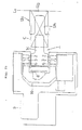
- the top and bottom cutting blades 4 are arranged to appear symmetrically in Fig. 1. By moving forward from the solid line in Fig. 8 toward the platform 1 on the left, they can cut areas shown by c6, c6 in Fig. 2 on the packaging material B of the package C. As means to move the pair of cutting blades 4, 4 closer to the platform 1 as shown above or move them backward to the solid line in Fig. 8 after cutting the packaging material B, as an example there is shown a frame 4a mounted with the pair of cutting blades 4, 4 which can be moved in the direction of left and right in Fig. 8 by the cylinders 4b.
- the cutting blade 5 is located as shown in Fig. 8 and by moving forward the solid line in the same figure, it can cut an area shown by c7 in Fig. 2 on the packaging material B of the package C placed on the platform 1.
- a cylinder 5a which will move the cutting blade 5 vertically in Fig. 8.
- a pair of holders 6, 6 that can press the two mutually opposing planes C1, C1 are arranged as shown in Figs. 8 and 11.
- a pair of holders 6, 6 shown on the left and right in Fig. 11 are on the solid line in the same figure, tey hold the package C on the platform 1.
- the pair of suction pads 2, 2 shown on the left and right in Fig. 11 are slightly withdrawn from the solid line in the same figure as shown by arrows in Fig.
- the area c1 cut by the cutting blades 3 is in the open condition and is ingeniously utilized in the embodiment. Specifically, ruler-like backplates are inserted through these areas as shown in Fig. 3 (e). Each backplate 7 can be placed in the space c8 partly between the packaging material B pulled outwardly by the suction pads 2, 2 and the packaged blanks A as shown in Fig. 6. Consequently by using these backplates 7 as underlays or supports when cutting the areas shown by c6, c6 in Fig. 2 with cutting blades 4, rim edges of the packaged blanks A are not damaged. Also by forming a longitudinal hollow 7a on the outside of each backplate 7 as shown in Figs. 5 and 6, and arranging the tip of the aforementioned cutting blade 4 to be positioned in the hollow 7a when it moves horizontally and cut the packaging material B, not only the tip of the blade but also the cutting position of the packaging material B are positioned without any shifting.
- a lever 7c that can be oscillated from a pivot 7b as shown in Fig. 10 can be linked to the backplate 7, and the other end of the lever 7c and the tip of the rod of the cylinder 7d can be linked with a lever 7e.
- lever 7c oscillates via lever 7e from pivot 7b as shown by dotted lines in this figure.
- the backplate 7 shown by solid line can move forward to the right in the figure as shown by dotted lines therein, and it can be inserted into the package C gradually from the tip.
- a backboard 8 is provided at the back of the platform 1 and on the left of Fig. 18 in order to determine the position of the package C on the platform 1. During the above operations, this backboard 8 is positioned to contact the back plane C4 shown in Fig. 2 of the package C.
- the holders 6 and the suction pads 2 are located on another platform 9 above the platform 1 as shown in Fig. 8, and the backboard 8 is located on another platform 10 above this platform 9.
- the platform 1 is able to move with respect to the frame 11 by a cylinder 1a
- the platform 9 is able to move with respect to the platform 1 by another cylinder D1 shown by dotted lines in Fig. 8 mounted on the platform 1 and a cylinder D2 mounted on the side of platform 9
- the platform 10 is able to move with respect to the platform 9 by another cylinder D3 shown by dotted lines in Fig. 9 mounted on the platform 9 and a cylinder D4 mounted on the side platform 10, respectively.
- Travelling distances of platforms, 1, 9 and 10 and the inter-platform positional relationships can be freely altered by operating all of the cylinders or only some of them, if desired.
- each package is placed on the platform 1 so that the plane C2 on which a cutting line c7 is to be provided is aligned to the one datum line L.
- the position of the platform 1 has to be varied according to the length of the package as shown by (a) - (d) in Fig. 16.
- the cylinder shown by 1a in Figs. 10 and 18 is operated.
- the position of the platform 1 can be varied according to the length of the package to be cut.
- the cutting blades 3, 3 When cutting a package of a length L1, the cutting blades 3, 3 shall be located at a distance l1 from the datum line L. When cutting a package of a length L2, the cutting blades 3, 3 shall be located at a distance of a length l2 from the datum line L. When cutting packages of lengths L3 and L4, the cutting blades 3, 3 shall be located at a distance l3 from the datum line L, and at the same time the positions of the pair of suction pads 2, 2 and the pair of holders 6, 6 that operate on the two mutually opposing planes C1, C1 of each package shall be varied and the backboard 8 shall be located at distance L1, L2, L3 and L4, respectively, from the datum line L.
- all of the above mentioned four cylinders D1 - D4 are activated or only some of them are activated leaving others inactive if required.
- a pair of cutting blades 3, 3 and a pair of holders 6, 6 are positioned so that the area at a distance l1 from the datum line L can be cut.
- the backboard 8 is positioned so that it contacts the back plane of the package of length L1 (the plane opposite to the datum line L, i.e., the left end plane of Fig. 16 (a) - (d).
- the fact that the platform 9 moves to the right for 105 mm from the initial position in this figure means that the pair of cutting blades 3, 3 mounted on it are moved 105 mm to the right in the figure from the fixed position where a package of length L1 is cut. If the pair of cutting blades 3, 3 are pressed and moved on a package of length L4, the area 105 mm closer to the datum line L from the cutting position of the package of the length L1 can be cut. In this case, the pair of suction pads, and the pair of holders 6 mounted on the platform 9 are also moved according to the movement of the pair of cutting blades 3, 3 respectively.
- the cylinder D3 and the cylinder D4 are moved for 20 mm and 25 mm respectively to the right in this figure as shown in Table 1.
- the cylinder D3 is mounted on the platform 9 as shown by dotted lines in Fig. 9, and its head is linked with a perpendicular plate 10a (solid lines) of the platform 10 above the platform 9 as shown in the same figure.
- the fact that the platform 10 moves 150 mm to the right from the initial position in the figure means that the backboard 8 mounted on it is moved 150 mm to the right in the figure from the fixed position where a package of length L1 is handled, and this backboard 8 contacts the back side of the package of the length L4 (the plane opposite to the datume line L, the extreme left plane of Fig. 16 (a) - (d)) to position it.
- a pair of cutting blades 3, 3, a pair of suction pads 2, 2, a pair of holders 6,6 and a backboard 8 can be positioned at desired places.
- one plane C2 of each package is positioned prior to loading on the platform 1 always at the same position.
- the positions of the one platform 1, the cutting blades 3, the suction pads, the holders 6 and backboard 8, can all be altered according to the lengths of packages. This means that even when packages to be cut are of different lengths, the platform 1 that support these will move to the prescribed position to meet them, and prescribed positions on the two mutually opposing planes of each package can be vertically cut with cutting blades 3. Further even when handling packages of different lengths, packaging material B can be vertically cut at prescribed positions for each package.
- the packaging material B of the package C on the platform 1 can be cut as described above.
- the platform 1 is at the position of the solid line in Fig. 19, which is the cutting line.
- the platform 1 is lowered as shown in Fig. 19 by dotted lines, and the cut packaging material B is opened at this position shown by dotted lines.
- a cylinder shown by 1b in Fig. 8 can be used to lower the entire platform 1 along with a frame 11.
- each package can be placed on the platform 1 so that each plane C2 to be provided with a cutting line c7 is positioned on one and the same datum line L.
- the package C can be stored in the transferring device 12 positioned at a fixed distance from the platform 1. But in this embodiment, the package C is carried in by two conveyors 14, 14 as shown in Figs. 13 and 19, and stored in the transferring device 12 by pushing onto the the transferring device 12 positioned between the both conveyors 14, 14 alternately or from one of them.
- This transferring device 12 is rotated thereafter as shown in Fig. 14 by single-dotted chain line, and is lowered to the fixed position beside the platform 1 as shown by double-dotted chain line in the same figure.
- a device (not shown) that can selectively lift and supply a package placed on the pallet to the two conveyors 14, 14 can be installed.
- the transferring device 12 shown in the embodiment is equipped with a storage box 12a with an L-shaped cross section as shown in Fig. 14, and the package C carried in by the two conveyors 14, 14 is pressed into the storage box 12a either alternately or continuously from either one of the two openings 12b (Fig. 14) shown on the left and right hand side in Fig. 13.
- pusher 15a, 15b are arranged above the two conveyors 14, 14 as shown in Fig. 13, and the pusher 15a and pusher 15b are alternately transferred from the solid line position in Fig. 13 as shown by chain line in the same figure via cylinder 16a and cylinder 16b respectively.
- This storage box 12a can be rotated from the solid line position in Fig. 14 as shown by the single-dotted chain line, and it can be further lowered to the prescribed position as shown by the double-dotted chain line in the same figure whereby the position is maintained.
- a method can be used, for example, in which the storage box 12a and the tip of the rod of cylinder 12c are connected by the lever 12d.
- This pusher 13 will move only a certain stroke from one of the two openings 12b of the storage box 12a, i.e., from the right hand side to the left hand side in Fig. 10. This allows the package inside the storage box 12a to be pushed out to the prescribed position. In other words, as described above, the storage box 12a and the package C stored inside are lowered so that their right ends are in the datum line Lo in Figs. 10, 15 and 16.
- the package C can be placed on the platform 1 so that the right end of the package C is on the datum line shown by L in Figs. 16 (a) - (d).
- This pusher 13 is slightly tilted until the storage box 12a is lowered as shown in Fig. 10. But before the end of the lowering of the storage box 12a it becomes vertical as shown by chain line in the same figure whereby the cylinder 13a serves as a kind of guide, and is moved by another cylinder 13b to the left in Fig. 10 by a certain stroke 1 o (Fig. 16) maintaining its position to push the package C inside the storage box 12a out to the prescribed position (on the line shown by L in Fig. 16), and place it onto the platform 1.
- the bottom part 12g of the storage box 12a is partially cut out as shown by 12h in Fig. 15. This is to avoid mutual collisions of the platform 1 and the storage box 12a that is lowered to the prescribed position when handling packages of different sizes (depth, length).
- the platform 1 is set to be positioned at the place shown by (a) in Fig. 16 when handling a package of length L1, handling of packages of lengths, L2, L3 and L4 that are shorter than that requires that the cylinder 1a (Fig. 18) is activated as above described and the position of platform 1 with respect to the storage box 12a is varied according to the length of the package.
- the part 1c at the front of the platform 1 is engaged in the cut-off part 12h of the storage box 12a and do not collide with one another.
- the package C is placed on the platform 1 and the packaging material B is cut and opened thereon.
- an example of a device to open the cut packaging material B by pairs of cutting blades 3, 3 and 4, 4 and a cutting blade 5, will be described in detail.
- the embodiment shows a case comprising a lever 17 to grasp the upper corner of the cut package C′ placed on the platform 1 (Fig. 2), a stopper 18 to transfer the package from the bottom to the top, and a stopper 19 to transfer the package from the top to the bottom.
- the bottom of the lever 17 is pivoted to the rod 17b of the lever 17a.
- the lever rotates from its solid line position in the same figure as shown by chain line with pivot 17c as the center, and its top grasps the upper corner or edge of the package C′.
- the mouth of the cut packaging material B opens slightly, and the tip of the stopper 18 penetrates into it to engage the open edges shown by (b) and moves upwards.
- the upper half of the packaging material B shown by (b1) opens as shown by Fig. 3 (g) and Fig. 7.
- the upper stopper 19 moves down and its tip hooks the open edges b′ of (b2) ofthe packaging material B in Fig. 7 and moves down too.
- the lower half of the packaging material shown by (b2) opens as shown by Fig. 3 (g) and Fig. 7.
- this opening operation can be performed to rip off the cut packaging material B by sucking either plane of the cut package C′.
- rectangular package comprising and covering a bundle of many flattened blanks A with packaging material B can be automatically cut and opened.
- the packaging material B is no longer necessary, and only the contents have to be taken out.
- this can be done by a robot shown by 20 in Fig. 19.
- This robot 20 is equipped with a grasping means comprising a top-and-bottom pair of forks 20a, 20a which approaches a cut package C ⁇ on platform 1 to take out only many stripped blanks A with the top-and-bottom pair of forks 20a, 20a as shown by Fig. 3 (h).
- the front side 1c of the platform 1 can be laid down as shown by chain line in Fig. 12 to avoid collisions of the bottom fork of the pair of forks 20a, 20a and the platform 1.
- a pusher 21 to push the empty packaging material B after the bulk of blanks A is taken out of the platform 1 by the pair of forks 20a, 20a and it can move forward to the chain line position from the solid line position in Fig. 18 by the activation of cylinder 21a.
- the empty packaging material pushed out by this pusher 21 can be discharged automatically by an device not shown.
Landscapes
- Engineering & Computer Science (AREA)
- Mechanical Engineering (AREA)
- Control And Other Processes For Unpacking Of Materials (AREA)
- Auxiliary Devices For And Details Of Packaging Control (AREA)
Applications Claiming Priority (2)
| Application Number | Priority Date | Filing Date | Title |
|---|---|---|---|
| JP63229667A JP2678630B2 (ja) | 1988-09-13 | 1988-09-13 | 包装材料で被包した方形伏包装物の切断・開封方法及びその装置 |
| JP229667/88 | 1988-09-13 |
Publications (1)
| Publication Number | Publication Date |
|---|---|
| EP0360136A1 true EP0360136A1 (de) | 1990-03-28 |
Family
ID=16895788
Family Applications (1)
| Application Number | Title | Priority Date | Filing Date |
|---|---|---|---|
| EP89116895A Withdrawn EP0360136A1 (de) | 1988-09-13 | 1989-09-12 | Verfahren und Vorrichtung zum Aufschneiden und Öffnen von rechteckigen Verpackungen |
Country Status (8)
| Country | Link |
|---|---|
| US (1) | US5048267A (de) |
| EP (1) | EP0360136A1 (de) |
| JP (1) | JP2678630B2 (de) |
| AU (1) | AU615332B2 (de) |
| CA (1) | CA1331449C (de) |
| DK (1) | DK169659B1 (de) |
| FI (1) | FI89030C (de) |
| NO (1) | NO301269B1 (de) |
Cited By (3)
| Publication number | Priority date | Publication date | Assignee | Title |
|---|---|---|---|---|
| US5476354A (en) * | 1994-03-23 | 1995-12-19 | Brown & Williamson Tobacco Corporation | Method and apparatus for opening soft-cup cigarette packs |
| EP0933300A1 (de) * | 1998-01-30 | 1999-08-04 | Nippon Paper Industries Co., Ltd. | Verfahren und Vorrichtung zum Öffnen einer Verpackung unter Verwendung von miteinander verbundenen Teilen derselben |
| CN102826267A (zh) * | 2012-09-06 | 2012-12-19 | 河北汇金机电股份有限公司 | 全自动款箱开箱机 |
Families Citing this family (21)
| Publication number | Priority date | Publication date | Assignee | Title |
|---|---|---|---|---|
| US5224827A (en) * | 1992-01-17 | 1993-07-06 | Tien Pao Liem | Bale encasing and de-casing system |
| DE4311421A1 (de) * | 1993-04-07 | 1994-10-13 | Vfi Verpackungstech | Verfahren und Vorrichtung zum Entfernen einer sichernden und/oder schützenden Folie |
| US5475967A (en) * | 1995-03-28 | 1995-12-19 | Levi; Hans L. | Apparatus and method for slitting boxes |
| US6694852B1 (en) * | 2000-11-10 | 2004-02-24 | Kellogg Company | Method and apparatus for cutting a case containing product |
| US7174695B2 (en) * | 2003-06-04 | 2007-02-13 | Porter Dan C | De-packaging machine |
| US7694614B2 (en) * | 2005-12-01 | 2010-04-13 | Walgreen, Co | Case cutter assembly |
| US7849776B2 (en) * | 2005-12-01 | 2010-12-14 | Walgreen Co. | Case cutter assembly |
| US20070125211A1 (en) * | 2005-12-01 | 2007-06-07 | Hilgendorf Dennis J | Case cutter assembly |
| US7720567B2 (en) * | 2005-12-09 | 2010-05-18 | Cornerstone Automation Systems, Inc. | Automated box opening apparatus |
| US7963086B2 (en) * | 2007-11-06 | 2011-06-21 | Porter Technologies, Llc | Package unbundling system |
| JP2010095296A (ja) * | 2008-10-17 | 2010-04-30 | Nihon Tetra Pak Kk | シート状包装材料で被包した方形状包装物の切断開封装置 |
| JP2010120669A (ja) * | 2008-11-18 | 2010-06-03 | Nihon Tetra Pak Kk | シート状包装材料で被包した方形状包装物の切断開封方法 |
| PL217989B1 (pl) * | 2010-07-05 | 2014-09-30 | Int Tobacco Machinery Poland | Sposób i urządzenie do niszczącego otwierania paczek papierosowych |
| IT1401846B1 (it) * | 2010-10-14 | 2013-08-28 | Co Ri M A S R L | Apparato e metodo per rimuovere un prodotto sterile da una confezione sterile che lo contiene |
| US9232818B1 (en) | 2012-07-03 | 2016-01-12 | Mr. Sajid Munawar | User friendly cigarette manufacturing machine |
| CN106628458A (zh) * | 2016-12-29 | 2017-05-10 | 楚天智能机器人(长沙)有限公司 | 一种基于智能拆包系统的拆包去膜方法 |
| US12116207B2 (en) | 2020-06-03 | 2024-10-15 | Robotica, Inc. | Tote handling system with tote handler and method of using same |
| US11981023B2 (en) | 2020-01-17 | 2024-05-14 | Robotica, Inc. | Tote handling system with integrated hand and method of using same |
| US11576425B2 (en) | 2020-07-06 | 2023-02-14 | Sajid Munawar | Self-cleaning cigarette manufacturing machine |
| IT202100004685A1 (it) * | 2021-03-01 | 2022-09-01 | Ima Spa | Procedimento e apparato per il trattamento automatico di involucri. |
| JP7664001B1 (ja) * | 2024-09-30 | 2025-04-17 | 株式会社和広エンジニアリング | フィルム切断装置 |
Citations (2)
| Publication number | Priority date | Publication date | Assignee | Title |
|---|---|---|---|---|
| US3889442A (en) * | 1972-03-13 | 1975-06-17 | Platmanufaktur Ab | Method of and device for removing a shrinkable plastic wrapping from a number of units, e.g. bottles, forming a substantially parallelepipedical body |
| DE3443362A1 (de) * | 1984-11-28 | 1986-05-28 | Kodak Ag, 7000 Stuttgart | Kopiergeraet |
Family Cites Families (4)
| Publication number | Priority date | Publication date | Assignee | Title |
|---|---|---|---|---|
| US2729885A (en) * | 1954-02-08 | 1956-01-10 | A J Wahl Inc | Apparatus for slitting cartons |
| FI41636C (fi) * | 1963-06-10 | 1969-12-10 | Billeruds Ab | Menetelmä ja laitteisto ei-jäykkää ainetta olevan päällyksen poistamiseksi pullopakkauksesta |
| US3386320A (en) * | 1966-03-10 | 1968-06-04 | Reynolds Tobacco Co R | Package-opening method and apparatus |
| US4843801A (en) * | 1988-05-25 | 1989-07-04 | Philip Morris Incorporated | Methods and apparatus for opening closed containers |
-
1988
- 1988-09-13 JP JP63229667A patent/JP2678630B2/ja not_active Expired - Fee Related
-
1989
- 1989-08-23 FI FI893945A patent/FI89030C/fi not_active IP Right Cessation
- 1989-09-08 AU AU41186/89A patent/AU615332B2/en not_active Ceased
- 1989-09-08 NO NO893605A patent/NO301269B1/no not_active IP Right Cessation
- 1989-09-12 EP EP89116895A patent/EP0360136A1/de not_active Withdrawn
- 1989-09-12 DK DK449089A patent/DK169659B1/da not_active IP Right Cessation
- 1989-09-13 US US07/406,447 patent/US5048267A/en not_active Expired - Lifetime
- 1989-09-13 CA CA000611245A patent/CA1331449C/en not_active Expired - Fee Related
Patent Citations (2)
| Publication number | Priority date | Publication date | Assignee | Title |
|---|---|---|---|---|
| US3889442A (en) * | 1972-03-13 | 1975-06-17 | Platmanufaktur Ab | Method of and device for removing a shrinkable plastic wrapping from a number of units, e.g. bottles, forming a substantially parallelepipedical body |
| DE3443362A1 (de) * | 1984-11-28 | 1986-05-28 | Kodak Ag, 7000 Stuttgart | Kopiergeraet |
Cited By (4)
| Publication number | Priority date | Publication date | Assignee | Title |
|---|---|---|---|---|
| US5476354A (en) * | 1994-03-23 | 1995-12-19 | Brown & Williamson Tobacco Corporation | Method and apparatus for opening soft-cup cigarette packs |
| EP0933300A1 (de) * | 1998-01-30 | 1999-08-04 | Nippon Paper Industries Co., Ltd. | Verfahren und Vorrichtung zum Öffnen einer Verpackung unter Verwendung von miteinander verbundenen Teilen derselben |
| CN102826267A (zh) * | 2012-09-06 | 2012-12-19 | 河北汇金机电股份有限公司 | 全自动款箱开箱机 |
| CN102826267B (zh) * | 2012-09-06 | 2013-12-25 | 河北汇金机电股份有限公司 | 全自动款箱开箱机 |
Also Published As
| Publication number | Publication date |
|---|---|
| FI893945A0 (fi) | 1989-08-23 |
| FI89030B (fi) | 1993-04-30 |
| CA1331449C (en) | 1994-08-16 |
| DK449089D0 (da) | 1989-09-12 |
| JPH0285121A (ja) | 1990-03-26 |
| NO893605D0 (no) | 1989-09-08 |
| FI893945A7 (fi) | 1990-03-14 |
| AU615332B2 (en) | 1991-09-26 |
| DK449089A (da) | 1990-03-14 |
| FI89030C (fi) | 1993-08-10 |
| NO893605L (no) | 1990-06-01 |
| US5048267A (en) | 1991-09-17 |
| JP2678630B2 (ja) | 1997-11-17 |
| DK169659B1 (da) | 1995-01-09 |
| AU4118689A (en) | 1990-03-22 |
| NO301269B1 (no) | 1997-10-06 |
Similar Documents
| Publication | Publication Date | Title |
|---|---|---|
| US5048267A (en) | Cutting and opening method and device for a rectangular package covered with packaging material | |
| US5059082A (en) | Method and apparatus for emptying a container | |
| US6189298B1 (en) | Method and apparatus for opening a package utilizing bonded portions thereof | |
| EP2736810B1 (de) | Vorrichtung und verfahren zum entpacken und zuführen von flach gefalteten und aufrecht stehenden packungsmänteln | |
| EP0361128B1 (de) | Vorrichtung zum Auspacken und Zuführen von Verpackungszuschnitten | |
| JP3261024B2 (ja) | 外部包装材に包まれたブランク堆積体の処理装置 | |
| JPH1191746A (ja) | 包装箱の開封装置 | |
| CN110539938A (zh) | 一种瓷砖包的自动拆包线及其拆包工艺 | |
| CN114919805B (zh) | 一种纸托成型装置及包装机 | |
| US5181652A (en) | Packaging | |
| JP2001335021A (ja) | 段ボール箱及びそれからの物品取り出し方法及び装置 | |
| CN121443518A (zh) | 利用盖子闭合顶部处开口的长方体盒子的包装方法及机器 | |
| KR102047422B1 (ko) | 용기묶음용 밴드의 절단 및 수거장치 | |
| JP2001018932A (ja) | 開封機構を備えたデパレタイザ | |
| JPS63162402A (ja) | 段ボ−ル箱等の箱へのワ−ク収容方法およびその装置 | |
| GB2237549A (en) | A method and a device for automatically forming a stack | |
| JPH0577808A (ja) | タイルの箱詰方法 | |
| JPH0317733B2 (de) | ||
| JPS63162403A (ja) | 集合ワ−クの段ボ−ル箱等の箱への収容装置 | |
| JPH0245342A (ja) | ラベル自動供給システムおよびラベル自動供給装置 | |
| JPS63162418A (ja) | チユ−ブ箱詰装置 | |
| JPH0796907A (ja) | 梱包装置 |
Legal Events
| Date | Code | Title | Description |
|---|---|---|---|
| PUAI | Public reference made under article 153(3) epc to a published international application that has entered the european phase |
Free format text: ORIGINAL CODE: 0009012 |
|
| AK | Designated contracting states |
Kind code of ref document: A1 Designated state(s): AT BE CH DE ES FR GB IT LI NL SE |
|
| 17P | Request for examination filed |
Effective date: 19900601 |
|
| 17Q | First examination report despatched |
Effective date: 19920320 |
|
| STAA | Information on the status of an ep patent application or granted ep patent |
Free format text: STATUS: THE APPLICATION HAS BEEN WITHDRAWN |
|
| 18W | Application withdrawn |
Withdrawal date: 19921214 |