EP0360366A2 - Boîtier moulé pour un disjoncteur électrique de puissance basse tension avec renfort contre une surpression - Google Patents
Boîtier moulé pour un disjoncteur électrique de puissance basse tension avec renfort contre une surpression Download PDFInfo
- Publication number
- EP0360366A2 EP0360366A2 EP89250035A EP89250035A EP0360366A2 EP 0360366 A2 EP0360366 A2 EP 0360366A2 EP 89250035 A EP89250035 A EP 89250035A EP 89250035 A EP89250035 A EP 89250035A EP 0360366 A2 EP0360366 A2 EP 0360366A2
- Authority
- EP
- European Patent Office
- Prior art keywords
- housing
- housing parts
- circuit breaker
- molding material
- partition
- Prior art date
- Legal status (The legal status is an assumption and is not a legal conclusion. Google has not performed a legal analysis and makes no representation as to the accuracy of the status listed.)
- Granted
Links
Images

Classifications
-
- H—ELECTRICITY
- H01—ELECTRIC ELEMENTS
- H01H—ELECTRIC SWITCHES; RELAYS; SELECTORS; EMERGENCY PROTECTIVE DEVICES
- H01H71/00—Details of the protective switches or relays covered by groups H01H73/00 - H01H83/00
- H01H71/02—Housings; Casings; Bases; Mountings
- H01H71/025—Constructional details of housings or casings not concerning the mounting or assembly of the different internal parts
- H01H71/0257—Strength considerations
-
- H—ELECTRICITY
- H01—ELECTRIC ELEMENTS
- H01H—ELECTRIC SWITCHES; RELAYS; SELECTORS; EMERGENCY PROTECTIVE DEVICES
- H01H9/00—Details of switching devices, not covered by groups H01H1/00 - H01H7/00
- H01H9/02—Bases, casings, or covers
- H01H9/04—Dustproof, splashproof, drip-proof, waterproof, or flameproof casings
- H01H9/042—Explosion-proof cases
Definitions
- the invention relates to an insulating molded-plastic housing of a low-voltage circuit breaker with two housing parts which are connected to one another along a part joint and with a wall part which is arranged transversely to the partial joint and serves to reinforce the molded-material housing against an overpressure acting on the inside.
- a molding material housing of this type has become known, for example, from DE-B-28 02 553.
- MCCB Molded Case Circuit Breaker
- ICCB Insulated Case Circuit Breaker
- the housing according to the mentioned DE-B-28 02 553 is designed to avoid damage due to internal overpressure due to switching arcs in such a way that the outer walls of the upper part of the housing overlap the outer walls of the lower part. It is thereby achieved that the spreading forces exerted by the gas pressure on the outer walls of the lower part are partially transferred into the outer walls of the upper part. With the same pressure load, a smaller material thickness can therefore be selected for the outer walls of the lower part.
- the wall part used for reinforcement is located in the upper part of the housing and is integrally formed on the side walls.
- the object of the invention is to improve the support of the side walls of the two housing parts and to provide a housing structure which is particularly suitable for low-voltage circuit breakers for the higher range of nominal currents and switching powers.
- the wall part is inserted between the housing parts and for this purpose has end webs with an undercut profile on opposite sides and that the housing parts in the region of the joint each have a groove adapted to the undercut profile, such that the grooves overlap the end webs of the wall part in a form-fitting manner.
- the wall part is directly involved in absorbing the expansion forces in the area of the side walls of both housing parts.
- the undercut design in the area of the parting joint also ensures that the side walls in the area of the parting joint cannot move against one another and thus there is no gas escape at this point.
- the grooves of the end faces of the housing parts can be arranged set back from the outer edge of the housing. This creates a labyrinth-like angled contact surface between the side walls and the reinforcing wall part. This creates a crawl path that is advantageous for electrical insulation and increases the resistance to the passage of switching gases.
- the wall part as a partition for dividing the molding material housing.
- the function of supporting the side walls of the molding material housing can advantageously be combined with an internal subdivision of the molding material housing into different functional spaces.
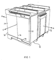
- a molded plastic housing 10 according to FIG. 1 has housing parts 12 and 14. Both housing parts 12 and 14 are formed by a fastener, z. B. screws, which are arranged in openings 18 of the housing part 12. Only one of the openings 18 is visible in FIG. 1, while a further opening 18 is arranged on the opposite side of the housing 10. The threaded part of the screws, not shown, extends into suitable threaded openings of the housing part 14. In this way, the housing parts 12 and 14 are held together against forces which act in the direction of arrows A and B in FIG. 1.
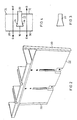
- the partition wall 22 has end webs 20.
- the profile of the end webs 20 can be seen in FIG. 3. Thereafter, an essentially dovetail-shaped section adjoins a parallel-walled section.
- FIG. 4 The interaction of the end webs 20 with the side walls 28 and 30 is shown in FIG. 4.
- the side walls 28 and 30 are provided in the region of the parting line 16 with recesses 24 and 26, respectively, which are adapted to the shape of the end web 20 shown in FIG.
- the side walls 28 and 30 overlap the end webs 20 in such a way that a positive connection is established and a mutual displacement of the side walls 28 and 30 at the parting line 16 is excluded.
- This is indicated by the double arrow pointing in the directions F and G in the region of the side wall 28 and the double arrow pointing in the directions D and E in the region of the side wall 30.
- the partition wall 22 with the end webs 20 acts as an additional stiffening of the side walls 28 and 30, since it can absorb tensile forces and therefore relieves the side walls of bending forces.
- FIG. 5 the installation of the partition 22 in the housing 10 can be seen particularly clearly from FIG. 5, in which the molded-material housing 10 is shown cut away in a top view.
- the molded plastic housing 10 and the partition wall 22 are provided with partitions for dividing the housing into three chambers for the three poles of a circuit breaker.
- the partition 22 In the area of the side walls 28 and 30 engages the partition 22 with its end webs 20 in the recesses 24 and 26 on the parting line 16 between the housing parts 12 and 14.
- the partition 22 is able to absorb tensile forces resulting from the internal overpressure on the side walls 28 and 30 which occurs during switching.
- the end webs 20 have a dovetail-shaped profile.
- other cross-sectional shapes are also suitable which, due to an undercut, have the same effect as a reinforcing part, e.g. B. a circular cross-section, hammer head cross-section or similar shapes.
Landscapes
- Breakers (AREA)
- Switch Cases, Indication, And Locking (AREA)
- Casings For Electric Apparatus (AREA)
Applications Claiming Priority (2)
| Application Number | Priority Date | Filing Date | Title |
|---|---|---|---|
| US07/246,470 US4899253A (en) | 1988-09-19 | 1988-09-19 | Molded case circuit breaker housing reinforcement |
| US246470 | 1988-09-19 |
Publications (3)
| Publication Number | Publication Date |
|---|---|
| EP0360366A2 true EP0360366A2 (fr) | 1990-03-28 |
| EP0360366A3 EP0360366A3 (fr) | 1991-11-06 |
| EP0360366B1 EP0360366B1 (fr) | 1994-11-30 |
Family
ID=22930815
Family Applications (1)
| Application Number | Title | Priority Date | Filing Date |
|---|---|---|---|
| EP89250035A Expired - Lifetime EP0360366B1 (fr) | 1988-09-19 | 1989-09-13 | Boîtier moulé pour un disjoncteur électrique de puissance basse tension avec renfort contre une surpression |
Country Status (6)
| Country | Link |
|---|---|
| US (1) | US4899253A (fr) |
| EP (1) | EP0360366B1 (fr) |
| JP (1) | JPH02197022A (fr) |
| CA (1) | CA1331775C (fr) |
| DE (1) | DE58908683D1 (fr) |
| ES (1) | ES2064429T3 (fr) |
Families Citing this family (7)
| Publication number | Priority date | Publication date | Assignee | Title |
|---|---|---|---|---|
| USD339565S (en) | 1991-06-13 | 1993-09-21 | Wila Leuchten Gmbh | Recessed lighting power system module |
| US5189596A (en) * | 1991-12-20 | 1993-02-23 | Westinghouse Electric Corp. | Transition for electrical apparatus |
| US6005207A (en) * | 1997-09-23 | 1999-12-21 | Siemens Energy & Automation, Inc. | Multi-part circuit breaker housing |
| US8944070B2 (en) * | 1999-04-07 | 2015-02-03 | Intuitive Surgical Operations, Inc. | Non-force reflecting method for providing tool force information to a user of a telesurgical system |
| DE19958945A1 (de) | 1999-11-26 | 2001-05-31 | Siemens Ag | Elektrisches Schaltgerät mit mehreren Gehäuseteilen |
| DE10323094B3 (de) * | 2003-05-16 | 2004-08-12 | Siemens Ag | Leistungsschalter |
| US20230377822A1 (en) * | 2022-05-20 | 2023-11-23 | Rockwell Automation Technologies, Inc. | Circuit breaker housing with two-stage structure |
Family Cites Families (8)
| Publication number | Priority date | Publication date | Assignee | Title |
|---|---|---|---|---|
| US3422235A (en) * | 1966-01-28 | 1969-01-14 | Heinemann Electric Co | Arcing grid case support means |
| US3329793A (en) * | 1966-01-28 | 1967-07-04 | Heinemann Electric Co | Circuit breaker case |
| FR2309032A1 (fr) * | 1975-04-21 | 1976-11-19 | Mang Ets Gerard | Appareils d'interruption de circuits electriques |
| DE2802553B1 (de) * | 1978-01-19 | 1979-01-18 | Siemens Ag | Niederspannungs-Leistungsschalter mit geteiltem Isolierstoffgehaeuse |
| JPS5663735A (en) * | 1979-10-27 | 1981-05-30 | Fuji Electric Co Ltd | Circuit breaker |
| US4389555A (en) * | 1982-04-05 | 1983-06-21 | Heinemann Electric Company | Circuit breaker with increased electrical spacing |
| US4598186A (en) * | 1983-05-09 | 1986-07-01 | Square D Company | Vent arrangement for high amperage molded case circuit breaker |
| US4524339A (en) * | 1983-05-09 | 1985-06-18 | Square D Company | Contact control arrangement for high amperage molded case circuit breaker |
-
1988
- 1988-09-19 US US07/246,470 patent/US4899253A/en not_active Expired - Lifetime
-
1989
- 1989-09-13 ES ES89250035T patent/ES2064429T3/es not_active Expired - Lifetime
- 1989-09-13 DE DE58908683T patent/DE58908683D1/de not_active Expired - Fee Related
- 1989-09-13 JP JP1239744A patent/JPH02197022A/ja active Pending
- 1989-09-13 EP EP89250035A patent/EP0360366B1/fr not_active Expired - Lifetime
- 1989-09-15 CA CA000611594A patent/CA1331775C/fr not_active Expired - Fee Related
Also Published As
| Publication number | Publication date |
|---|---|
| US4899253A (en) | 1990-02-06 |
| EP0360366B1 (fr) | 1994-11-30 |
| CA1331775C (fr) | 1994-08-30 |
| DE58908683D1 (de) | 1995-01-12 |
| EP0360366A3 (fr) | 1991-11-06 |
| JPH02197022A (ja) | 1990-08-03 |
| ES2064429T3 (es) | 1995-02-01 |
Similar Documents
| Publication | Publication Date | Title |
|---|---|---|
| DE69315063T2 (de) | Hochstromsicherung | |
| EP0107611A1 (fr) | Dispositif de sectionnement avec lamelles de contact pontant pour appareil interrupteur débrochable | |
| DE1590733A1 (de) | Elektrischer Leistungsschalter | |
| EP0360366B1 (fr) | Boîtier moulé pour un disjoncteur électrique de puissance basse tension avec renfort contre une surpression | |
| EP0898779A1 (fr) | Disjoncteur pour basse tension avec rails de raccordement | |
| DE69111571T2 (de) | Mehrpoliger Drehschalter. | |
| DE3101532C2 (de) | Stecksockel für Niederspannungs-Schutzschalter | |
| DE10312820B4 (de) | Lichtbogenlöschblechanordnung für einen elektrischen Schalter, insbesondere einen elektrischen Leitungsschutzschalter | |
| EP0180537A2 (fr) | Interrupteur du type MCCB à deux parts de boîte | |
| EP0916148A1 (fr) | Boitier de chambre de commutation pour un sectionneur de puissance et modules servant a fabriquer ce boitier de chambre de commutation | |
| EP0223732A1 (fr) | Disjoncteur multipolaire de puissance basse tension avec barres de courant | |
| EP1297547B1 (fr) | Barrette a connexions pour dispositifs et appareils electriques utilisables pour differents courants nominaux et comportant une cavite | |
| DE2732963A1 (de) | Schuetz | |
| DE19939710A1 (de) | Anschlußschienen für elektrische Geräte und Apparate für verschiedene Nennströme | |
| EP1065683B1 (fr) | Disjoncteur aves des bornes pour plusieurs intensités nominales | |
| EP1374264B1 (fr) | Ensemble contact de commutation pour un commutateur electrique | |
| EP1267464B1 (fr) | Isolateur pour système de barres électriques, et assemblage d'isolation faisant usage de tels isolateurs | |
| DE2543959A1 (de) | Adapter fuer sicherungslastschalter zur befestigung auf stromsammelschienen | |
| EP0436578B1 (fr) | Boitier pour un commutateur en charge moyenne tension a isolation par gaz | |
| DE69834897T2 (de) | Verwechslungsschutzanordnung für elektrische Schaltgeräte, insbesondere für Leistungsschalter und Differenzstromschutzschalter | |
| DE3735191C2 (fr) | ||
| DE3850732T2 (de) | Gekapselte Gehäuse- und Deckelanordnung für Strombegrenzungsschalter. | |
| DE3931810A1 (de) | Formgehaeuse fuer strombegrenzungsschalter | |
| EP0340700B1 (fr) | Boîtier pour appareils de commutation en série | |
| DE759073C (de) | Schmelzsicherung mit Kontaktmessern |
Legal Events
| Date | Code | Title | Description |
|---|---|---|---|
| PUAI | Public reference made under article 153(3) epc to a published international application that has entered the european phase |
Free format text: ORIGINAL CODE: 0009012 |
|
| AK | Designated contracting states |
Kind code of ref document: A2 Designated state(s): DE ES FR GB IT |
|
| 17P | Request for examination filed |
Effective date: 19901220 |
|
| PUAL | Search report despatched |
Free format text: ORIGINAL CODE: 0009013 |
|
| AK | Designated contracting states |
Kind code of ref document: A3 Designated state(s): DE ES FR GB IT |
|
| 17Q | First examination report despatched |
Effective date: 19940203 |
|
| GRAA | (expected) grant |
Free format text: ORIGINAL CODE: 0009210 |
|
| AK | Designated contracting states |
Kind code of ref document: B1 Designated state(s): DE ES FR GB IT |
|
| REF | Corresponds to: |
Ref document number: 58908683 Country of ref document: DE Date of ref document: 19950112 |
|
| REG | Reference to a national code |
Ref country code: ES Ref legal event code: FG2A Ref document number: 2064429 Country of ref document: ES Kind code of ref document: T3 |
|
| ITF | It: translation for a ep patent filed | ||
| ET | Fr: translation filed | ||
| GBT | Gb: translation of ep patent filed (gb section 77(6)(a)/1977) |
Effective date: 19950210 |
|
| PLBE | No opposition filed within time limit |
Free format text: ORIGINAL CODE: 0009261 |
|
| 26N | No opposition filed | ||
| REG | Reference to a national code |
Ref country code: GB Ref legal event code: IF02 |
|
| PGFP | Annual fee paid to national office [announced via postgrant information from national office to epo] |
Ref country code: GB Payment date: 20030904 Year of fee payment: 15 |
|
| PGFP | Annual fee paid to national office [announced via postgrant information from national office to epo] |
Ref country code: ES Payment date: 20030912 Year of fee payment: 15 |
|
| PGFP | Annual fee paid to national office [announced via postgrant information from national office to epo] |
Ref country code: FR Payment date: 20030930 Year of fee payment: 15 |
|
| PGFP | Annual fee paid to national office [announced via postgrant information from national office to epo] |
Ref country code: DE Payment date: 20031117 Year of fee payment: 15 |
|
| PG25 | Lapsed in a contracting state [announced via postgrant information from national office to epo] |
Ref country code: GB Free format text: LAPSE BECAUSE OF NON-PAYMENT OF DUE FEES Effective date: 20040913 |
|
| PG25 | Lapsed in a contracting state [announced via postgrant information from national office to epo] |
Ref country code: ES Free format text: LAPSE BECAUSE OF NON-PAYMENT OF DUE FEES Effective date: 20040914 |
|
| PG25 | Lapsed in a contracting state [announced via postgrant information from national office to epo] |
Ref country code: DE Free format text: LAPSE BECAUSE OF NON-PAYMENT OF DUE FEES Effective date: 20050401 |
|
| GBPC | Gb: european patent ceased through non-payment of renewal fee |
Effective date: 20040913 |
|
| PG25 | Lapsed in a contracting state [announced via postgrant information from national office to epo] |
Ref country code: FR Free format text: LAPSE BECAUSE OF NON-PAYMENT OF DUE FEES Effective date: 20050531 |
|
| REG | Reference to a national code |
Ref country code: FR Ref legal event code: ST |
|
| PG25 | Lapsed in a contracting state [announced via postgrant information from national office to epo] |
Ref country code: IT Free format text: LAPSE BECAUSE OF NON-PAYMENT OF DUE FEES;WARNING: LAPSES OF ITALIAN PATENTS WITH EFFECTIVE DATE BEFORE 2007 MAY HAVE OCCURRED AT ANY TIME BEFORE 2007. THE CORRECT EFFECTIVE DATE MAY BE DIFFERENT FROM THE ONE RECORDED. Effective date: 20050913 |
|
| REG | Reference to a national code |
Ref country code: ES Ref legal event code: FD2A Effective date: 20040914 |