EP0361064A2 - Optischer Spektrum-Analysator mit hoher Messleistung - Google Patents
Optischer Spektrum-Analysator mit hoher Messleistung Download PDFInfo
- Publication number
- EP0361064A2 EP0361064A2 EP89115267A EP89115267A EP0361064A2 EP 0361064 A2 EP0361064 A2 EP 0361064A2 EP 89115267 A EP89115267 A EP 89115267A EP 89115267 A EP89115267 A EP 89115267A EP 0361064 A2 EP0361064 A2 EP 0361064A2
- Authority
- EP
- European Patent Office
- Prior art keywords
- light
- optical
- measured
- spectroscope
- polarized
- Prior art date
- Legal status (The legal status is an assumption and is not a legal conclusion. Google has not performed a legal analysis and makes no representation as to the accuracy of the status listed.)
- Ceased
Links
Images


Classifications
-
- G—PHYSICS
- G01—MEASURING; TESTING
- G01J—MEASUREMENT OF INTENSITY, VELOCITY, SPECTRAL CONTENT, POLARISATION, PHASE OR PULSE CHARACTERISTICS OF INFRARED, VISIBLE OR ULTRAVIOLET LIGHT; COLORIMETRY; RADIATION PYROMETRY
- G01J3/00—Spectrometry; Spectrophotometry; Monochromators; Measuring colours
- G01J3/28—Investigating the spectrum
-
- G—PHYSICS
- G01—MEASURING; TESTING
- G01J—MEASUREMENT OF INTENSITY, VELOCITY, SPECTRAL CONTENT, POLARISATION, PHASE OR PULSE CHARACTERISTICS OF INFRARED, VISIBLE OR ULTRAVIOLET LIGHT; COLORIMETRY; RADIATION PYROMETRY
- G01J3/00—Spectrometry; Spectrophotometry; Monochromators; Measuring colours
- G01J3/02—Details
- G01J3/0205—Optical elements not provided otherwise, e.g. optical manifolds, diffusers, windows
- G01J3/0224—Optical elements not provided otherwise, e.g. optical manifolds, diffusers, windows using polarising or depolarising elements
-
- G—PHYSICS
- G01—MEASURING; TESTING
- G01J—MEASUREMENT OF INTENSITY, VELOCITY, SPECTRAL CONTENT, POLARISATION, PHASE OR PULSE CHARACTERISTICS OF INFRARED, VISIBLE OR ULTRAVIOLET LIGHT; COLORIMETRY; RADIATION PYROMETRY
- G01J3/00—Spectrometry; Spectrophotometry; Monochromators; Measuring colours
- G01J3/02—Details
- G01J3/04—Slit arrangements slit adjustment
-
- G—PHYSICS
- G01—MEASURING; TESTING
- G01J—MEASUREMENT OF INTENSITY, VELOCITY, SPECTRAL CONTENT, POLARISATION, PHASE OR PULSE CHARACTERISTICS OF INFRARED, VISIBLE OR ULTRAVIOLET LIGHT; COLORIMETRY; RADIATION PYROMETRY
- G01J3/00—Spectrometry; Spectrophotometry; Monochromators; Measuring colours
- G01J3/02—Details
- G01J3/08—Beam switching arrangements
-
- G—PHYSICS
- G01—MEASURING; TESTING
- G01J—MEASUREMENT OF INTENSITY, VELOCITY, SPECTRAL CONTENT, POLARISATION, PHASE OR PULSE CHARACTERISTICS OF INFRARED, VISIBLE OR ULTRAVIOLET LIGHT; COLORIMETRY; RADIATION PYROMETRY
- G01J3/00—Spectrometry; Spectrophotometry; Monochromators; Measuring colours
- G01J3/12—Generating the spectrum; Monochromators
- G01J3/14—Generating the spectrum; Monochromators using refracting elements, e.g. prisms
-
- G—PHYSICS
- G01—MEASURING; TESTING
- G01J—MEASUREMENT OF INTENSITY, VELOCITY, SPECTRAL CONTENT, POLARISATION, PHASE OR PULSE CHARACTERISTICS OF INFRARED, VISIBLE OR ULTRAVIOLET LIGHT; COLORIMETRY; RADIATION PYROMETRY
- G01J3/00—Spectrometry; Spectrophotometry; Monochromators; Measuring colours
- G01J3/12—Generating the spectrum; Monochromators
- G01J3/18—Generating the spectrum; Monochromators using diffraction elements, e.g. grating
- G01J3/1804—Plane gratings
-
- G—PHYSICS
- G01—MEASURING; TESTING
- G01J—MEASUREMENT OF INTENSITY, VELOCITY, SPECTRAL CONTENT, POLARISATION, PHASE OR PULSE CHARACTERISTICS OF INFRARED, VISIBLE OR ULTRAVIOLET LIGHT; COLORIMETRY; RADIATION PYROMETRY
- G01J4/00—Measuring polarisation of light
-
- G—PHYSICS
- G01—MEASURING; TESTING
- G01J—MEASUREMENT OF INTENSITY, VELOCITY, SPECTRAL CONTENT, POLARISATION, PHASE OR PULSE CHARACTERISTICS OF INFRARED, VISIBLE OR ULTRAVIOLET LIGHT; COLORIMETRY; RADIATION PYROMETRY
- G01J1/00—Photometry, e.g. photographic exposure meter
- G01J1/10—Photometry, e.g. photographic exposure meter by comparison with reference light or electric value provisionally void
- G01J1/16—Photometry, e.g. photographic exposure meter by comparison with reference light or electric value provisionally void using electric radiation detectors
- G01J1/1626—Arrangements with two photodetectors, the signals of which are compared
-
- G—PHYSICS
- G01—MEASURING; TESTING
- G01J—MEASUREMENT OF INTENSITY, VELOCITY, SPECTRAL CONTENT, POLARISATION, PHASE OR PULSE CHARACTERISTICS OF INFRARED, VISIBLE OR ULTRAVIOLET LIGHT; COLORIMETRY; RADIATION PYROMETRY
- G01J3/00—Spectrometry; Spectrophotometry; Monochromators; Measuring colours
- G01J3/28—Investigating the spectrum
- G01J3/447—Polarisation spectrometry
Definitions
- the present invention relates to an optical spectrum analyzer which uses spectroscope elements of the dispersion type such as the diffraction grating and prism and, more particularly, it relates to an optical spectrum analyzer capable of measuring, with high accuracy, the absolute value of optical spectrum every wavelength of light to be measured.
- the measured light entering through the inlet slit is introduced onto and diffracted by the diffraction grating.
- the light thus diffracted is received by the light receiving means through the outlet slit.
- Optical strength representing signal which calculates from a photoelectric conversion signal corresponding to angle ⁇ of the diffraction grating rotated and which is applied from the light receiving means is regarded as an optical spectrum value at every wavelength of the light to be measured.
- the polarization direction in the measured light is not certain but optional to have angle ⁇ relative to grooves of diffraction grating 3.
- wavelength sensitivity characteristics P( ⁇ ) of the grating in a direction parallel to its grooves is different from wavelength sensitivity characteristics S( ⁇ ) in a direction perpendicular to its grooves.
- the ratio of light (component P) polarized parallel to the grooves of the grating and light (component S) polarized perpendicular to the grooves thereof changes as the polarization direction in the measured light becomes different. It cannot be believed therefore that the optical spectrum value thus obtained is always correct every wavelength ⁇ .
- an optical spectrum analyzer wherein the diffracted light is divided into parallel- and perpendicularly-polarized lights by a polarizing element and these parallel- and perpendicularly-polarized lights are detected independently of the other, as shown in Fig. 10.
- Measured light (a) entering from outside is passed through inlet slit 1, processed to have parallel rays by collimator mirror 2, and introduced onto diffraction grating 3.
- the light diffracted by diffraction grating 3 is collected by camera mirror 4 which is a concave lens, and it is applied to polarizing element 7 through outlet slit 5 and lens 6.
- This polarizing element 7 is made of calcite and serves to divide the light, which has been applied to it, into light (b) polarized parallel to the grooves of diffraction grating 13 and light (c) polarized perpendicular to the grooves thereof.
- These parallel- and perpendicularly-polarized lights (b) and (c) are received by light receiving means 8 and 9, respectively.
- optical strengths obtained by the photoelectric conversion signals at an optional wavelength ⁇ applied from parallel- and perpendicularly-polarized lights receiving devices 8 and 9 be I X ( ⁇ ) and I Y ( ⁇ )
- wavelength sensitivity characteristics in both of the directions relative to diffraction grating 3 and including conversion efficiency be S( ⁇ ) and P( ⁇ ), as shown in Fig. 12.
- Polarizing element 7 which serves to divide the light, which has been diffracted by diffraction grating 3, into light polarized parallel to the grooves of diffraction grating 3 and light polarized perpendicular to the grooves thereof is usually made of calcite.
- optical level is made low because of the scattering of light in calcite and because of the reflecting of light when it enters into calcite, and ratio S/N of parallel- and perpendicularly-polarized lights (b) and (c) applied from polarizing element 7 is also made low.
- High reliability is not paid therefore to optical strengths I X ( ⁇ ) and I Y ( ⁇ ) which are obtained in both of the directions from optical photoelectric conversion signals applied from light receiving devices 8 and 9.
- one light diffracted by diffraction grating 3 is divided into two polarized lights (b) and (c) by polarizing element 7. Absolute levels of divided polarized lights (b) and (c) are thus made low. Therefore, ratio S/N of each of these polarized lights (b) and (c) is further made low. As the result, ratio S/N of each of the above-mentioned optical strengths I X ( ⁇ ) and I Y ( ⁇ ) is further made low and reliability which is paid to absolute spectrum value I( ⁇ ) finally calculated from equation (3) is thus reduced.
- the diffracting efficiency of the diffraction grating depends upon polarized waves in the case of the conventional optical spectrum analyzer of the diffraction grating type.
- level measuring sensibility is made low because of loss caused by the polarizing element inserted.
- the present invention is intended to eliminate the polarized-waves dependency of the diffraction grating while keeping the level measuring sensibility high.
- An object of the present invention is to provide an optical spectrum analyzer wherein the optical strength ratio of each of parallel- and perpendicularly-polarized lights can be obtained and the optical strength of light not polarized is corrected by the optical strength ratio to enhance the ratio S/N of an absolute value of the optical spectrum at every wavelength of light to be measured and analyzed and thus enhance the measuring accuracy of the analyzer itself.
- an optical spectrum analyzer comprising: spectroscope means of the dispersion type for receiving light to be measured and emitting it as dispersed light which corresponds to each of wavelengths to be measured; optical-path switching means for directing the dispersed light emitted from the spectroscope means to pass through first and second paths; first photoelectric converter means for receiving the light which is directed to pass through the first path by the optical-path switching means; polarizing/separating means for polarizing and separating the light, which has been directed to pass through the second path by the optical-path switching means, into two polarized lights; second and third photoelectric converter means for respectively receiving the two polarized lights polarized and separated by the polarizing/separating means; and arithmetical process means for correcting a first optical spectrum strength according to an output from the first photoelectric converter means with at least a ratio of second and third optical spectrum strengths according to outputs from the second and third photoelectric converter means, to whereby calculate absolute spectrum values
- an optical spectrum analyzer comprising: a spectroscope element of the dispersion type for diffracting measured light entering through an inlet slit; measured-light receiving means for receiving the light, which has been diffracted by the spectroscope element of the dispersion type, through an outlet slit; a polarizing element for dividing the light, which has been emitted through the outlet slit, into light polarized parallel to grooves of the spectroscope element of the dispersion type and light polarized perpendicular to the grooves of the spectroscope element; means for receiving the parallel-polarized light applied from the polarizing element; means for receiving the perpendicularly-polarized light applied from the polarizing element; optical-path switching means interposed between the outlet slit and the measured-light receiving means to selectively switch or direct the optical path of the light, which has been emitted through the outlet slit, to the polarizing element; means for calculating
- the optical-path switching means in the second example of the optical spectrum analyzer is inserted in the optical path of the measured light extending to the spectroscope element of the dispersion type to selectively direct the measured light, which is not diffracted yet, to the polarizing element.
- the optical strength of light, which has been diffracted by the spectroscope element of the dispersion type while operating the optical-path switching means is measured by the measured-light receiving means and optical strength I O ( ⁇ ) is obtained from the photoelectric conversion signal of light which is not polarized and separated yet.
- the light which has been diffracted by the spectroscope element of the dispersion type while operating the optical-path switching means is then polarized into both of the directions to calculate optical strength ratio A( ⁇ ) between the optical strength representing signals of each of the polarized lights.
- Wavelength sensitivity characteristics P O ( ⁇ ), S O ( ⁇ ), P( ⁇ ) and S( ⁇ ) including conversion efficiencies of measured-light receiving means and parallel- and perpendicularly-polarized lights receiving means in those directions parallel and perpendicular to the grooves of the spectroscope element of the dispersion type are already known. Therefore, true optical strengths I P ( ⁇ ) and I S ( ⁇ ) of light incident onto the diffraction grating in either of the directions can be calculated from optical strength ratio A( ⁇ ) and optical strength I O ( ⁇ ) of light not divided. Absolute spectrum value I( ⁇ ) which does not depend upon the polarization direction of the measured light can be thus calculated.
- This absolute spectrum value I( ⁇ ) includes, as error causes, only optical strength I O ( ⁇ ) of the light which is not divided yet and whose ratio S/N is large, and optical strength ratio A( ⁇ ). Ratio S/N of absolute spectrum value I( ⁇ ) can be thus raised to a greater extent, as compared with that attained by the conventional analyzer.
- the optical-path switching means is located before the spectroscope element of the dispersion type.
- Light applied to the polarizing element is therefore same as the measured light which is not diffracted yet.
- the optical strength of the measured light which is not diffracted yet is larger at every wavelength than that of the light which has been diffracted.
- the optical strength of each of the polarized lights becomes larger accordingly.
- Ratio S/N of optical strength ratio A( ⁇ ) obtained can be thus raised to a remarkable extent.
- Absolute spectrum value I( ⁇ ) includes, as error causes, only optical strength I O ( ⁇ ) of the light which is not polarized and separated yet and whose ratio S/N is large, and optical strength ratio A( ⁇ ).
- Ratio S/N of absolute spectrum value I( ⁇ ) can be thus raised to a greater extent, as compared with that attained by the conventional analyzer.
- optical strength ratio A( ⁇ ) is not measured every wavelength ⁇ . Therefore, the optical spectrum analyzer according to the present invention is quite useful for spectrum-analyzing the measured light whose optical strength ratio is not greatly changed by each of wavelengths.
- Fig. 1 shows a first embodiment of the optical spectrum analyzer according to the present invention, particularly an arrangement of its main portion.
- Measured light (a) inputted from outside is introduced to collimator mirror 12 through inlet slit 11 and its rays are made parallel to one another by collimator mirror 12. These rays are then made incident onto diffraction grating 13 which is rotated by motor 26.
- the rays thus diffracted by diffraction grating 13 are collected by camera mirror 14 which is a concave mirror lens, and passed through outlet slit 15.
- the light passed through outlet slit 15 is passed through slits 17a of optical-path changing device 17 by lens 16 and then received by measured-light receiving device 18.
- optical-path changing device 17 is a disk-like chopper interposed in and tilted relative to the optical path extending from lens 16 to measured-light receiving device 18.
- This disk-like chopper has slits 17a radially directed and mirror portions 17b each interposed between adjacent slits 17a, and it is rotated round its axial center 17c by motor 27 such as a stepping motor and a DC motor.
- motor 27 such as a stepping motor and a DC motor.
- the light coming out of outlet slit 15 is introduced onto the rotating disk and when the light comes to one of slits 17a it is allowed to pass slit 17a and reach measured-light receiving device 18.
- mirror portion 17b When the light comes to mirror portion 17b, however, it is reflected to come onto polarizing element 19.
- This polarizing element 19 is made of calcite (crystalline material of the monoclinic system) and serves to divide the incident light into one (b) polarized parallel to the grooves of diffraction grating 13 and the other (c) polarized perpendicular to the grooves of diffraction grating 13.
- Parallel-polarized light (b) and perpendicularly-polarized light (c) are received by light receiving devices 20 and 21, respectively.
- These light receiving devices 18, 20 and 21 convert the lights thus received into photoelectric conversion signals which denote optical strengths of these lights.
- These photoelectric conversion signals outputted from light receiving devices 18, 20 and 21 are converted into digital signals I O ( ⁇ ), I X ( ⁇ ) and I Y ( ⁇ ), which represent the optical strengths, by A/D converters 22, 23 and 24 and these digital signals are applied to arithmetical process section 25 which includes microcomputers, for example.
- Optical strength ratio A( ⁇ ) and absolute spectrum value I( ⁇ ) of each of wavelengths ⁇ are calculated at arithmetical process section 25.
- optical-path switching device 17 When slit 17a of optical-path switching device 17 is in coincidence with the optical path in the case of this optical spectrum analyzer, the light diffracted by diffraction grating 13 can advance straight without changing its optical path and it is received, as light having no insertion loss of the polarizing element 19, by measured-light receiving device 18. It is then applied, as optical strength I O ( ⁇ ), to arithmetical process section 25 through A/D converter 22.
- mirror portion 17b of optical-path switching device 17 When mirror portion 17b of optical-path switching device 17 is in coincidence with the optical path, the light diffracted by diffraction grating 13 is reflected by mirror portion 17b to change its optical path, and it is then divided into parallel- and perpendicularly-polarized lights (b) and (c) by means of polarizing element 19. These parallel- and perpendicularly-polarized lights (b) and (c) are received, as those having insertion loss of the polarizing element 19, by light receiving devices 20 and 21 and then applied, as measured optical strengths I X ( ⁇ ) and I Y ( ⁇ ), to arithmetical process section 25 through A/D converters 23 and 24.
- diffraction grating 13 and the light receiving devices 20 and 21 including wavelength characteristics of the polarizing element 19, has such wavelength sensitivity characteristics P( ⁇ ) and S( ⁇ ) as shown in Fig. 12.
- I S ( ⁇ )/I P ( ⁇ ) ⁇ I Y ( ⁇ )/S( ⁇ ) ⁇ / ⁇ I X ( ⁇ )/P( ⁇ ) ⁇ (4)
- Optical strength I O ( ⁇ ) measured by light receiving device 18 can be expressed by the following equation (5), providing that the wavelength sensitivity characteristic in both of the directions be P O ( ⁇ ) and S O ( ⁇ ):
- I O ( ⁇ ) I P ( ⁇ ) ⁇ P O ( ⁇ ) + I S ( ⁇ ) ⁇ S O ( ⁇ )(5)
- Ratio A( ⁇ ) of optical strengths I P ( ⁇ ) and I S ( ⁇ ) of parallel- and perpendicularly-polarized rays of the incident light is expressed by ⁇ I P ( ⁇ )/I S ( ⁇ ) ⁇ .
- I( ⁇ ) I O ( ⁇ ) ⁇ 1+A( ⁇ ) ⁇ / ⁇ A( ⁇ ) ⁇ S O ( ⁇ )+P O ( ⁇ ) ⁇ (6)
- absolute spectrum value I( ⁇ ) can be calculated from equation (6) when optical strength I O ( ⁇ ) of light which is received by measured-light receiving device 18 and which has no insertion loss of polarizing element 19 but high ratio of S/N is corrected by wavelength sensitivity characteristics P( ⁇ ), S( ⁇ ) and P O ( ⁇ ), S O ( ⁇ ) which are efficiency factors of each receiving device to diffraction grating 13 in either of the directions, and also by optical strength ratio A( ⁇ ) between the polarized lights calculated from P( ⁇ ) and S( ⁇ ) received by light receiving devices 20 and 21.
- absolute spectrum value I( ⁇ ) obtained from equation (6) does not depend upon the direction (angle ⁇ ) of measured light (a) polarized relative to the grooves of diffraction grating 13.
- Ratio S/N of absolute spectrum value I( ⁇ ) obtained from equation (6) in the case of the optical spectrum analyzer according to the present invention will be compared with that of absolute spectrum value I( ⁇ ) obtained from equation (3) in the case of the conventional analyzer.
- Wavelength sensitivity characteristics P( ⁇ ), S( ⁇ ) and P O ( ⁇ ), S O ( ⁇ ) can be previously and precisely measured and set at the memory area (not shown) of a random access memory (RAM) and the like in arithmetical process section 25.
- Absolute spectrum value I( ⁇ ) obtained from equation (3) is determined by ratios S/N of optical strengths I X ( ⁇ ) and I Y ( ⁇ ) of divided polarized lights (b) and (c). Each of these ratios S/N influences equally ratio S/N of total I( ⁇ ).
- absolute spectrum value I( ⁇ ) obtained from equation (6) is determined by ratio S/N of optical strength I O ( ⁇ ) of light not divided and also by ratio S/N of optical strength ratio A( ⁇ ) between optical strengths I X ( ⁇ ) and I Y ( ⁇ ) of polarized lights (b) and (c).
- Ratio S/N of optical strength I O ( ⁇ ) of light not divided contributes to ratio S/N of total I( ⁇ ) to a great extent, but the contribution of ratio S/N of optical strength ratio A( ⁇ ) is low. Therefore, ratio S/N of total I( ⁇ ) approaches to that of optical strength I O ( ⁇ ) of light not polarized and separated.
- Ratio S/N of optical strength I O ( ⁇ ) of light not divided is extremely higher than that of each of optical strengths I X ( ⁇ ) and I Y ( ⁇ ) of divided polarized lights (b) and (c).
- ratio S/N of absolute spectrum value I( ⁇ ) obtained from equation (6) in the case of this embodiment can be enhanced to a greater extend of about 6 dB, as compared with that of absolute spectrum value I( ⁇ ) obtained from equation (3) in the case of the conventional analyzer.
- the measurement accuracy of the optical spectrum analyzer can be thus enhanced.
- Fig. 2 shows a second embodiment of the optical spectrum analyzer according to the present invention. Same components as those in Fig. 1 will be denoted by same reference numerals and description on these components will be omitted.
- optical-path switching devices 17 which has been interposed between outlet slit 15 and measured-light receiving device 18 in Fig. 1 is now located before inlet slit 11.
- measured-light (a) coming from outside is passed through one of slits 17a of optical-path switching device 17, introduced onto diffraction grating 13 through inlet slit 11 and diffracted by diffraction grating 13.
- the diffracted lights are collected by camera mirror 14, received by measured-light receiving device 18 through outlet slit 15 and lens 16 and converted into a photoelectric conversion signal which denotes the optical strength of the light received.
- This photoelectric conversion signal is further converted into a digital signal, which denotes optical strength I O ( ⁇ ), by means of A/D converter 22 and this digital value is applied to arithmetical process section 25.
- measured-light (a) introduced is reflected by mirror portion 17b of optical-path switching device 17 and directed onto polarizing element 19.
- Measured-light (a) which has been introduced onto polarizing element 19 but not diffracted yet is polarized and separated into light (b) which is polarized parallel to the grooves of diffraction grating 13 and light (c) which is polarized perpendicular to the grooves of diffraction grating 13.
- Parallel- and perpendicularly-polarized lights (b) and (c) thus polarized and separated are converted into photoelectric conversion signals by parallel- and perpendicularly-polarized lights receiving devices 20 and 21, respectively.
- These optical strengths representing signals are further converted into digital signal, which denotes optical strengths I X and I Y , by A/D converters 23 and 24 and then applied to arithmetical process section 25.
- Arithmetical process section 25 calculates optical strength ratio A from the following equation (7), using optical strengths IX and IY applied.
- A ⁇ I Y /S( ⁇ ) ⁇ / ⁇ I X /P( ⁇ ) ⁇ (7) Therefore, optical strength ratio between optical strengths I S and I P of lights incident onto diffraction grating 13 in either of the directions does not depend upon wavelength ⁇ but can be expressed by optical strength ratio A.
- A I S /I P (8)
- Optical strengths I X and I Y of polarized lights (b) and (c) which are not diffracted but include all wavelength components are extremely higher, as compared with optical strengths I X ( ⁇ ) and I Y ( ⁇ ) of polarized lights (b) and (c) which have been diffracted to wavelengths ⁇ as shown in Fig. 1.
- Absolute spectrum value I( ⁇ ) which is expressed by equation (9) and obtained by the analyzer shown in Fig. 2 can enhance its ratio S/N to greater extent, as compared with absolute spectrum value I( ⁇ ) which is expressed by equation (6) and obtained by the analyzer shown in Fig. 1.
- optical strength ratio A of optical strengths I X and I Y of polarized lights (b) and (c) is not greatly changed by wavelength ⁇ . Therefore, the second optical spectrum analyzer is quite useful for spectrum-analyzing measured-light (a) whose optical strength ratio A is not greatly changed by wavelength ⁇ .
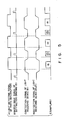
- optical-path switching device 17 Every time when optical-path switching device 17 is rotated by one step in response to motor drive signal shown by A in Fig. 3, slit 17a and mirror portion 17b of device 17 are alternately interposed in the optical path.
- optical-path switching device 17 is rotated by two steps, therefore, optical strengths at one wavelength ⁇ can be obtained by light receiving devices 20, 21 and 18, respectively.
- diffraction grating 13 is rotated by one step in response to motor drive signal shown by B in Fig. 3 to shift wavelength ⁇ to be measured to a next wavelength.
- This shift of wavelength ⁇ to be measured can be attained when the diffraction grating 13 is rotated by motor 26 shown in Figs. 1 and 2.
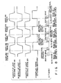
- Figs. 4 and 5 show another example of measuring optical strengths by light receiving devices 18, 20 and 21.
- a photo-interrupter which comprises a light-emitting diode (LED) and a photo-diode (PD) for detecting slits 17a of optical-path switching device 17 is added to sample the optical strength representing signal of each of light receiving devices 18, 20 and 21 in response to light detection signal applied from this photo-interrupter.
- diffraction grating 13 is rotated by one step, receiving level I O1 measured by light receiving device 18 and offset levels I X2 and I Y2 of the receiving devices 20 and 21 are sampled after the rising of light detection signal.
- Offset level I O1 of receiving device 18 and receiving levels I X1 and I Y1 by light receiving devices 20 and 21 are sampled after the falling of light detection signal. Trully receiving levels I O ( ⁇ ), I X ( ⁇ ) and I Y ( ⁇ ) are calculated from the differences between receiving levels and offset levels.
- Fig. 6 shows a third embodiment of the optical spectrum analyzer according to the present invention which has an arrangement more concrete than that of the first optical spectrum analyzer. Same components as those in Fig. 1 will be denoted by same reference numerals and description on these components will be omitted.
- optical spectrum analyzer of the third embodiment uses drive control and arithmetical process section 25A which includes a peripheral circuit comprising a micro-processor (CPU), a RAM, a read-only memory (ROM) and the like.
- CPU micro-processor
- RAM random access memory
- ROM read-only memory
- Diffraction grating 13, inlet and outlet slits 11 and 15, and optical-path switching device 17 are provided with their respective drive sections 13A, 15A and 17A each including a motor for driving its corresponding means.
- Grating, slits and chopper drive signals which will be described later are supplied from drive control and arithmetical process section 25A to these drive sections 13A, 15A and 17A.
- Optical-path switching device 17 is provided with photo-interrupter 30 to take sampling timings, as seen in Fig. 4.
- This photo-interrupter 30 is connected to drive control and arithmetical process section 25A through sampling timing detecting section 31.
- Display section 32 including a cathode ray tube (CRT) and the like is also connected to drive control and arithmetical process section 25A to display absolute spectrum value I( ⁇ ) and the like finally obtained.
- CTR cathode ray tube
- Drive control and arithmetical process section 25A drives diffraction grating 13, inlet and outlet slits 11 and 15 through grating and slits drive sections 13A and 15A at such a timing as shown at the left end of E in Fig. 8 and in response to grating and slits drive signals.
- Grating 13, inlet and outlet slits 11 and 15 are thus set at those positions which correspond to a start wavelength (step S11).
- drive control and arithmetical process section 25A detects first sampling timing 1 at the rising of such a detected waveform as shown at D in Fig.
- step S12 said detected waveform being obtained through photointerrupter 30 and sampling timing detecting section 31 which are attached to optical-path switching device 17 and driven at a certain rotation speed through chopper drive section 17A and in response to chopper drive signal (step S12).
- drive control and arithmetical process section 25A reads in levels sampled through light receiving devices 18, 20, 21 and A/D converters 22, 23, 24 relating to the light passed through and shielded by optical-path switching device 17, and carries out arithmetical process on the basis of the light levels as shown in the first embodiment of the present invention (steps S13 and S14).
- Second sampling timing 2 is similarly detected at the falling of the sampling timing detecting waveform shown at D in Fig.
- step S15 levels relating to the light passed through and shielded by optical-path switching device 17 are read in and a necessary arithmetical process is carried out (steps S16 and S17). It is arranged that drive control and arithmetical process section 25A carries out an operation to get light levels of the measured light (or incident light) as well as such operation as shown in detail in the first embodiment of the present invention to correct sensitivity.
- step S18 Drive control and arithmetical process section 25A applies the levels of the incident light thus obtained to display section 32 (step S18).
- step S19 for answering whether or not the sweep measurement is finished says "no”
- grating 13, inlet and outlet slits 11 and 15 are again set to correspond to a next wavelength to be measured (step S20) and the detection of sampling timings is repeated, starting from step S12 and ending with step S20. The measurement of spectrum to be swept is thus finished.
- level measuring and light receiving device 18 is provided independently of polarized-light 30 receiving devices 20 and 21 which serve to measure the state of polarized light and detect the ratio of P and S waves.
- measured light passes through optical-path switching device 17 which also serves as the chopper, but it enters directly into level measuring and light receiving device 18. This can prevent detection sensitivity from being damaged.
- the measured light also enters into polarized-light receiving devices 20 and 21, passing through optical-path switching device 17.
- receiving device 20 and 21 only detect the state of polarized light to count input levels of the measured-light backward. Therefore, loss of light caused by polarizing element 19 gives no influence to the detection sensitivity attained.
- Values detected by receiving device 20 and 21 are subjected to arithmetical process together with angles (or wavelengths) of diffraction grating 13 set and diffraction efficiency data (relating to every polarized component) of diffraction grating 13, and used as correction values which are added to level measuring values obtained by device 18. This enables spectrum measurement to be achieved with a high level likelihood ratio.
- the influence of polarizing characteristics of the diffraction grating can be eliminated without damaging the sensitivity of measuring levels. This makes it possible to realize an optical spectrum analyzer which has a high sensitivity (6 dB higher) and a high likelihood ratio.
- the present invention is not limited to its above-described embodiments, but an A/O (acoustical/optical) switch may be used instead of optical-path switching device 17.
- A/O acoustical/optical
- Prism 93 having an aluminum film 93a evaporated on a rear surface thereof shown in Fig. 9 may be used instead of the diffraction grating.
- the optical strength ratio of lights polarized parallel and perpendicular to the grooves of the spectroscope of the dispersioh type is calculated and the optical strength of light not polarized is corrected by this optical strength ratio.
- This can enhance the ratio S/N of absolute values which are obtained every wavelength relating to the optical spectrum of light to be measured, the light being analyzed according to wavelengths. As the result, the measurement accuracy of the analyzer can be enhanced.
- the two polarized lights may be applied to lights other than lights polarized parallel and perpendicular to the grooves of the diffraction grating.
Landscapes
- Physics & Mathematics (AREA)
- Spectroscopy & Molecular Physics (AREA)
- General Physics & Mathematics (AREA)
- Spectrometry And Color Measurement (AREA)
Applications Claiming Priority (4)
| Application Number | Priority Date | Filing Date | Title |
|---|---|---|---|
| JP205027/88 | 1988-08-18 | ||
| JP20502788 | 1988-08-18 | ||
| JP194057/89 | 1989-07-28 | ||
| JP19405789A JPH02138835A (ja) | 1988-08-18 | 1989-07-28 | 光スペクトラム分析装置 |
Publications (2)
| Publication Number | Publication Date |
|---|---|
| EP0361064A2 true EP0361064A2 (de) | 1990-04-04 |
| EP0361064A3 EP0361064A3 (de) | 1991-01-16 |
Family
ID=26508275
Family Applications (1)
| Application Number | Title | Priority Date | Filing Date |
|---|---|---|---|
| EP19890115267 Ceased EP0361064A3 (de) | 1988-08-18 | 1989-08-18 | Optischer Spektrum-Analysator mit hoher Messleistung |
Country Status (2)
| Country | Link |
|---|---|
| US (1) | US4995724A (de) |
| EP (1) | EP0361064A3 (de) |
Cited By (4)
| Publication number | Priority date | Publication date | Assignee | Title |
|---|---|---|---|---|
| EP0417709A3 (en) * | 1989-09-12 | 1991-11-21 | Fujitsu Limited | Spectrum measuring equipment |
| US5128797A (en) * | 1991-02-11 | 1992-07-07 | The United States Of America As Represented By The Administrator Of The National Aeronautics And Space Administration | Non-mechanical optical path switching and its application to dual beam spectroscopy including gas filter correlation radiometry |
| EP0540966A1 (de) * | 1991-11-06 | 1993-05-12 | Hewlett-Packard Company | Optischer Spektralanalysator mit einem Doppelmonochromator |
| WO2014060466A1 (en) | 2012-10-16 | 2014-04-24 | Avantes Holding B.V. | Dual beam device for simultaneous measurement of spectrum and polarization of light |
Families Citing this family (14)
| Publication number | Priority date | Publication date | Assignee | Title |
|---|---|---|---|---|
| EP0702437B1 (de) * | 1994-08-16 | 1998-05-27 | Hewlett-Packard GmbH | Verfahren und Vorrichtung zur Analyse der Charakteristiken einer optischen Schaltung |
| JPH08122706A (ja) * | 1994-10-19 | 1996-05-17 | Advantest Corp | 偏光解消装置及びこれを用いた分光装置 |
| US6636306B2 (en) | 2000-01-07 | 2003-10-21 | Exfo Electro-Optical Engineering Inc. | Optical spectrum analyzer |
| US7509048B2 (en) * | 2001-07-20 | 2009-03-24 | Essex Corporation | Method and apparatus for optical signal processing using an optical tapped delay line |
| JP4228666B2 (ja) * | 2002-11-25 | 2009-02-25 | ソニー株式会社 | 光学ピックアップ装置、記録再生装置及びギャップ検出方法 |
| US7209230B2 (en) | 2004-06-18 | 2007-04-24 | Luckoff Display Corporation | Hand-held spectra-reflectometer |
| US7340127B1 (en) * | 2005-01-31 | 2008-03-04 | Sunrise Telecom Incorporated | Full-band optical spectrum analyzer and method |
| US7283232B2 (en) * | 2005-06-06 | 2007-10-16 | Duke University | Optical spectroscopy with overlapping images |
| US7233394B2 (en) | 2005-06-20 | 2007-06-19 | Luckoff Display Corporation | Compact spectrometer |
| US7817274B2 (en) * | 2007-10-05 | 2010-10-19 | Jingyun Zhang | Compact spectrometer |
| WO2009070459A1 (en) | 2007-11-30 | 2009-06-04 | Jingyun Zhang | Miniature spectrometers working with cellular phones and other portable electronic devices |
| TWI426248B (zh) * | 2011-11-16 | 2014-02-11 | Ind Tech Res Inst | 光譜量測系統與光譜量測方法 |
| DE102016225344A1 (de) * | 2016-12-16 | 2018-06-21 | Fraunhofer-Gesellschaft zur Förderung der angewandten Forschung e.V. | System zur Analyse von elektromagnetischer Strahlung und Bauelement zur Herstellung desselben |
| US20220390281A1 (en) * | 2021-06-04 | 2022-12-08 | Viavi Solutions Inc. | Providing polarization diversity and reducing polarization dependent loss (pdl) in a grating-based optical spectrum analyzer (osa) |
Family Cites Families (6)
| Publication number | Priority date | Publication date | Assignee | Title |
|---|---|---|---|---|
| FR2223690B3 (de) * | 1973-03-29 | 1977-01-14 | Nk Verwaltungs Ag | |
| US3924950A (en) * | 1974-09-16 | 1975-12-09 | Perkin Elmer Corp | Atomic absorption spectroscopy with background correction |
| GB2013362B (en) * | 1978-01-20 | 1982-07-14 | Hoffmann La Roche | Spectrophotometer |
| DD159565A1 (de) * | 1981-05-25 | 1983-03-16 | Joachim Mohr | Verfahren und anordnung zur durchfuehrung einer spektralanalyse |
| JPS6111622A (ja) * | 1984-06-27 | 1986-01-20 | Hitachi Ltd | 分光光度計 |
| JPS63284432A (ja) * | 1987-05-15 | 1988-11-21 | Iwatsu Electric Co Ltd | 分光測光装置 |
-
1989
- 1989-08-14 US US07/393,805 patent/US4995724A/en not_active Expired - Fee Related
- 1989-08-18 EP EP19890115267 patent/EP0361064A3/de not_active Ceased
Cited By (5)
| Publication number | Priority date | Publication date | Assignee | Title |
|---|---|---|---|---|
| EP0417709A3 (en) * | 1989-09-12 | 1991-11-21 | Fujitsu Limited | Spectrum measuring equipment |
| US5128797A (en) * | 1991-02-11 | 1992-07-07 | The United States Of America As Represented By The Administrator Of The National Aeronautics And Space Administration | Non-mechanical optical path switching and its application to dual beam spectroscopy including gas filter correlation radiometry |
| EP0540966A1 (de) * | 1991-11-06 | 1993-05-12 | Hewlett-Packard Company | Optischer Spektralanalysator mit einem Doppelmonochromator |
| WO2014060466A1 (en) | 2012-10-16 | 2014-04-24 | Avantes Holding B.V. | Dual beam device for simultaneous measurement of spectrum and polarization of light |
| WO2014060118A1 (en) | 2012-10-16 | 2014-04-24 | Avantes Holding B.V. | Dual beam device for simultaneous measurement of spectrum and polarization of light |
Also Published As
| Publication number | Publication date |
|---|---|
| US4995724A (en) | 1991-02-26 |
| EP0361064A3 (de) | 1991-01-16 |
Similar Documents
| Publication | Publication Date | Title |
|---|---|---|
| EP0361064A2 (de) | Optischer Spektrum-Analysator mit hoher Messleistung | |
| KR0151711B1 (ko) | 다중채널 광학 모니터링 시스템 | |
| US5337081A (en) | Triple view imaging apparatus | |
| EP0381053B1 (de) | Verfahren zum Betrieb eines Spektrophotometers | |
| US4851657A (en) | Focus condition detecting device using weighted center or contrast evaluation | |
| US4330209A (en) | Spectrophotometer receiving a variable quantity of light | |
| US4758086A (en) | Apparatus for measuring spectral power of a light beam | |
| US5276499A (en) | Spectrophotometer | |
| EP0439804A2 (de) | Rotations-Detektorapparat | |
| US4644659A (en) | Transit | |
| JP2004226257A (ja) | マルチポート分光器とそれを用いた光スペクトラムアナライザ | |
| JPH02138835A (ja) | 光スペクトラム分析装置 | |
| JP3122697B2 (ja) | 偏光面検出器 | |
| SU1578504A1 (ru) | Фотоприемное устройство | |
| JPH01250737A (ja) | 自動化学分析装置 | |
| JP2830834B2 (ja) | 焦点検出装置 | |
| JPH0943056A (ja) | 測光量装置 | |
| JP3392898B2 (ja) | 格子干渉型変位測定装置 | |
| JP3204726B2 (ja) | エッジセンサ | |
| JP2892670B2 (ja) | 光スペクトラムアナライザ | |
| JPS62909A (ja) | 自動焦点制御装置 | |
| JP2746259B2 (ja) | 焦点検出装置 | |
| JPH08304176A (ja) | 分光計 | |
| JPH10104069A (ja) | 分光分析装置 | |
| JPH1137798A (ja) | 位置検出装置 |
Legal Events
| Date | Code | Title | Description |
|---|---|---|---|
| PUAI | Public reference made under article 153(3) epc to a published international application that has entered the european phase |
Free format text: ORIGINAL CODE: 0009012 |
|
| AK | Designated contracting states |
Kind code of ref document: A2 Designated state(s): DE FR GB |
|
| PUAL | Search report despatched |
Free format text: ORIGINAL CODE: 0009013 |
|
| AK | Designated contracting states |
Kind code of ref document: A3 Designated state(s): DE FR GB |
|
| 17P | Request for examination filed |
Effective date: 19910425 |
|
| 17Q | First examination report despatched |
Effective date: 19930128 |
|
| STAA | Information on the status of an ep patent application or granted ep patent |
Free format text: STATUS: THE APPLICATION HAS BEEN REFUSED |
|
| 18R | Application refused |
Effective date: 19930718 |