EP0361105A1 - Margeur, notamment pour machines à imprimer des feuilles - Google Patents
Margeur, notamment pour machines à imprimer des feuilles Download PDFInfo
- Publication number
- EP0361105A1 EP0361105A1 EP89115817A EP89115817A EP0361105A1 EP 0361105 A1 EP0361105 A1 EP 0361105A1 EP 89115817 A EP89115817 A EP 89115817A EP 89115817 A EP89115817 A EP 89115817A EP 0361105 A1 EP0361105 A1 EP 0361105A1
- Authority
- EP
- European Patent Office
- Prior art keywords
- sheet
- catch
- locking
- control device
- cam mechanism
- Prior art date
- Legal status (The legal status is an assumption and is not a legal conclusion. Google has not performed a legal analysis and makes no representation as to the accuracy of the status listed.)
- Granted
Links
- 230000000903 blocking effect Effects 0.000 description 7
- 230000008878 coupling Effects 0.000 description 4
- 238000010168 coupling process Methods 0.000 description 4
- 238000005859 coupling reaction Methods 0.000 description 4
- 230000001133 acceleration Effects 0.000 description 3
- 230000000737 periodic effect Effects 0.000 description 2
- 230000006835 compression Effects 0.000 description 1
- 238000007906 compression Methods 0.000 description 1
- 238000005516 engineering process Methods 0.000 description 1
- 238000009434 installation Methods 0.000 description 1
- 239000003550 marker Substances 0.000 description 1
- 239000013641 positive control Substances 0.000 description 1
Images

Classifications
-
- B—PERFORMING OPERATIONS; TRANSPORTING
- B65—CONVEYING; PACKING; STORING; HANDLING THIN OR FILAMENTARY MATERIAL
- B65H—HANDLING THIN OR FILAMENTARY MATERIAL, e.g. SHEETS, WEBS, CABLES
- B65H7/00—Controlling article feeding, separating, pile-advancing, or associated apparatus, to take account of incorrect feeding, absence of articles, or presence of faulty articles
- B65H7/20—Controlling associated apparatus
-
- B—PERFORMING OPERATIONS; TRANSPORTING
- B65—CONVEYING; PACKING; STORING; HANDLING THIN OR FILAMENTARY MATERIAL
- B65H—HANDLING THIN OR FILAMENTARY MATERIAL, e.g. SHEETS, WEBS, CABLES
- B65H5/00—Feeding articles separated from piles; Feeding articles to machines
- B65H5/08—Feeding articles separated from piles; Feeding articles to machines by grippers, e.g. suction grippers
- B65H5/10—Reciprocating or oscillating grippers, e.g. suction or gripper tables
Definitions
- the invention relates to a sheet application device for sheet processing and processing machines, in particular for sheet printing machines, with front marks periodically pivotable by a non-lockable cam mechanism and a locking device which can be controlled by a sheet control device and which holds the sheets on the system table when locked.
- Sheet feeding devices are provided with a device for blocking the sheet feed in order to prevent the entry of sheets that do not fit properly or of double sheets into the machine, for example a printing machine. These locking devices become effective if a sheet control device detects a position that does not match or if the sheet is missing or the double sheet is being fed.
- locking marks that can be held in place on the feed table are provided for blocking the sheet feed, which, as long as there is no blocking, perform periodic pivoting movements synchronously with the front marks.
- the swivel movements are generated by a cam and a roller lever and transmitted to a branded drive shaft via a coupling gear.
- Each front mark and each blocking mark is assigned a drive gear with a double rocker arm, which is rotatably mounted on the brand drive shaft and non-positively in one direction of rotation via a tension spring and in the other direction of rotation via an adjustable stop with a drive lever is bound, which is fixedly arranged on the brand drive shaft.
- the periodic swiveling movement of the brand drive shaft is transmitted from the drive lever in the swiveling phase of the brands to the system table via the adjustable stop and in the swiveling phase from the tension spring to the double rocker arm, which is firmly connected to the brands via a coupling.
- the double rocker of the locking marks additionally has a stop piece on a lever arm which, in the locked position, bears against a locking block of a locking lever combination which can be actuated by an electromagnet. If the sheet system does not fit, the sheet control device actuates the electromagnet, which causes the locking block to block the double rockers of the locking marks via the stop piece, thereby holding the locking marks on the feed table.
- the invention has for its object to provide a sheet feeder of the type mentioned, which is characterized by simple structure and great reliability and which is suitable for high machine speeds.
- this object is achieved in that the pivoting movement is transmitted only by rigid members of the cam mechanism in the pivoting phase of the front brands and that
- Locking device is formed by catch hooks which are moved into a catching position on the system table by a control device independent of the cam mechanism when the sheet control device is blocked.
- a Bo genanlegevorraum is created in which the movement of the front brands is completely independent of the movement of the catch hook of the locking device. This creates the possibility to design the drive of the front brands so that only low spring forces are required even at high machine speeds, since the highest accelerations that occur in the pivoting phase of the front brands do not have to be transmitted with the help of spring forces.
- the front mark drive can be designed in the form of a positive control in the sheet application device according to the invention, which permits high accelerations and thus high machine speeds.
- the invention also prevents parts of the drive device of the brands from being blocked, impact loads and resulting interference vibrations are largely avoided.
- the drive of the locking hooks which do not have to fulfill a brand function, can be simple and relatively light, so that no significant inertia forces occur when the locking hook is actuated, and no interference vibrations are caused. It is also advantageous that the sheet feed device can be actuated at any time, since the pivoting of the catch hooks out of the blocking position is independent of the particular machine position.
- hen hen that the catch hooks pivotally mounted on the system table are movable by pneumatic short-stroke cylinders from their pivoting position into the catch position, the short-stroke cylinders being controllable by an electro-pneumatic quick-closing solenoid valve.
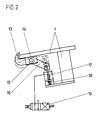
- the sheets coming from a sheet feeder are brought up to front marks 2.
- the front brands 2 are fastened on a front brand drive shaft 3, which is mounted below the system table 1 and can be rotated via a drive lever 4.
- the drawing shows the front marks 2 in the sheet alignment position, in which they are pressed 5 by train springs. Stops (not shown) ensure precise positioning of the front marks 2.
- the swung-away position of the front marks 2 is indicated by dash-dotted lines.
- the drive lever 4 is connected by a coupling rod 6 to a double-armed roller lever 7 which is pivotally mounted on an axis 8 fixed to the frame.
- a pressure spring 9 By means of a pressure spring 9, the roller lever 7 with the roller 10 mounted at its free end is pressed against a front mark control cam 11, which is driven synchronously with the machine connected to the sheet application device.
- the direction of rotation of the control cam 11 is indicated in the drawing by an arrow 12.
- the swiveling of the front marks 2 takes place through the sector a of the control cam 11, the roller lever 7 being under tension the pressure spring 9 is moved to the dot-dash position.
- the high acceleration forces that occur are transmitted directly from the control cam 11 via the roller 10 to the roller lever 7 and are forwarded by this via the coupling rod 6 and the drive lever 7 to the front marker drive shaft 3. It is therefore only in the pivoting phase of the front brands 2 rigid members of the front brand drive effective.
- the spring force of the pressure spring 9 can remain comparatively low, since for the pivoting phase he has a considerably larger angle of rotation of the control cam and thus a considerably larger period of time is available.
- the device for blocking the sheet feed consists of catch hooks 13 which are attached to a shaft 14.
- the shaft 14 is mounted below the system table 1 in bearings 15 and is pivoted via a fork lever 16 which can be pivoted by a pneumatic short-stroke cylinder 17 which is also attached to the system table 1.
- the short-stroke cylinder 17 contains a compression spring 18 which strives to move the piston of the cylinder into a basic position in which the catch hooks 13 are pivoted out of their catch position. This basic position is shown in the drawing with dash-dotted lines.
- the short-stroke cylinder 17 is controlled by an electro-pneumatic quick-closing solenoid valve 19, which is controlled electrically by a sheet control device and is switched to a position in which the short-stroke cylinder 17 with a Compressed air shaft connects.
- the thus actuated piston of the short-stroke cylinder 17 ver pivots via the fork lever 16, the shaft 14, whereby the catch hook 13 get into the catch position and block the sheet feed to the machine. If there is again a fitting sheet on the front marks 2, the sheet control device switches the quick-closing solenoid valve 19 back into its starting position, thereby relieving the piston of the short-stroke cylinder 17 and the catch hooks 13 are pivoted away.
- the catch position for machine run is decoupled via the manual signal "paper run”.
Landscapes
- Engineering & Computer Science (AREA)
- Mechanical Engineering (AREA)
- Sheets, Magazines, And Separation Thereof (AREA)
- Character Spaces And Line Spaces In Printers (AREA)
- Impact Printers (AREA)
- Massaging Devices (AREA)
- Inking, Control Or Cleaning Of Printing Machines (AREA)
- Supply, Installation And Extraction Of Printed Sheets Or Plates (AREA)
- Electrostatic Charge, Transfer And Separation In Electrography (AREA)
- Steering Control In Accordance With Driving Conditions (AREA)
- Time Recorders, Dirve Recorders, Access Control (AREA)
Priority Applications (1)
| Application Number | Priority Date | Filing Date | Title |
|---|---|---|---|
| AT89115817T ATE75665T1 (de) | 1988-09-06 | 1989-08-28 | Bogenanlegevorrichtung, insbesondere fuer bogendruckmaschinen. |
Applications Claiming Priority (2)
| Application Number | Priority Date | Filing Date | Title |
|---|---|---|---|
| DE3839260 | 1988-09-06 | ||
| DE3830260A DE3830260A1 (de) | 1988-09-06 | 1988-09-06 | Bogenanlegevorrichtung, insbesondere fuer bogendruckmaschinen |
Publications (2)
| Publication Number | Publication Date |
|---|---|
| EP0361105A1 true EP0361105A1 (fr) | 1990-04-04 |
| EP0361105B1 EP0361105B1 (fr) | 1992-05-06 |
Family
ID=6362377
Family Applications (1)
| Application Number | Title | Priority Date | Filing Date |
|---|---|---|---|
| EP89115817A Expired - Lifetime EP0361105B1 (fr) | 1988-09-06 | 1989-08-28 | Margeur, notamment pour machines à imprimer des feuilles |
Country Status (4)
| Country | Link |
|---|---|
| EP (1) | EP0361105B1 (fr) |
| AT (1) | ATE75665T1 (fr) |
| DE (2) | DE3830260A1 (fr) |
| ES (1) | ES2032086T3 (fr) |
Cited By (2)
| Publication number | Priority date | Publication date | Assignee | Title |
|---|---|---|---|---|
| EP0775576A3 (fr) * | 1995-11-21 | 1997-07-30 | Heidelberger Druckmasch Ag | Commande des pinces pour une pince préliminaire entraînée de façon cyclique et oscillante dans une machine d'impression de feuilles |
| CN103662887A (zh) * | 2013-12-02 | 2014-03-26 | 温州启迪机械有限公司 | 一种卡纸裱合机的送纸机构 |
Families Citing this family (3)
| Publication number | Priority date | Publication date | Assignee | Title |
|---|---|---|---|---|
| DE102008010008B4 (de) | 2008-02-20 | 2018-10-31 | Koenig & Bauer Ag | Verfahren und Vorrichtung zum Sperren der Bogenzufuhr einer Druckmaschine |
| DE102009008776B4 (de) | 2008-03-17 | 2021-05-27 | Heidelberger Druckmaschinen Ag | Vorrichtung zum Ausrichten von Bogen an Anschlägen |
| CN107757100A (zh) * | 2017-11-27 | 2018-03-06 | 东台市康宏纸箱厂 | 一种用于纸张印刷的组合上摆式前规 |
Citations (3)
| Publication number | Priority date | Publication date | Assignee | Title |
|---|---|---|---|---|
| DE1100043B (de) * | 1958-08-15 | 1961-02-23 | Leipziger Buchbindereimaschine | Greifer an Druck- und Buchbinderei-Maschinen zum Erfassen und Festhalten von Bogen aus Papier, Pappe oder aehnlichem Material |
| DE2113750B2 (de) * | 1970-04-01 | 1973-09-06 | VEB Polygraph Leipzig, Kombinat für polygraphische Maschinen und Ausrüstungen, χ 7050 Leipzig | Vorrichtung zum erfassen von bogenfoermigem material |
| DE2851263A1 (de) * | 1978-02-23 | 1979-09-06 | Polygraph Leipzig | Einrichtung zur sperrung der greifer eines vorgreifers |
Family Cites Families (3)
| Publication number | Priority date | Publication date | Assignee | Title |
|---|---|---|---|---|
| DE569729C (de) * | 1931-02-05 | 1933-02-07 | Kalle & Co Ag | Verfahren zum kantengerechten Ausrichten der Bogen |
| DE1786314B1 (de) * | 1968-08-08 | 1971-11-04 | Polygraph Leipzig | Vorrichtung zum sperren der bogenzufuhr |
| US3888478A (en) * | 1974-05-23 | 1975-06-10 | Sperry Rand Corp | Sheet limiter |
-
1988
- 1988-09-06 DE DE3830260A patent/DE3830260A1/de active Granted
-
1989
- 1989-08-28 EP EP89115817A patent/EP0361105B1/fr not_active Expired - Lifetime
- 1989-08-28 AT AT89115817T patent/ATE75665T1/de not_active IP Right Cessation
- 1989-08-28 ES ES89115817T patent/ES2032086T3/es not_active Expired - Lifetime
- 1989-08-28 DE DE8989115817T patent/DE58901332D1/de not_active Expired - Lifetime
Patent Citations (3)
| Publication number | Priority date | Publication date | Assignee | Title |
|---|---|---|---|---|
| DE1100043B (de) * | 1958-08-15 | 1961-02-23 | Leipziger Buchbindereimaschine | Greifer an Druck- und Buchbinderei-Maschinen zum Erfassen und Festhalten von Bogen aus Papier, Pappe oder aehnlichem Material |
| DE2113750B2 (de) * | 1970-04-01 | 1973-09-06 | VEB Polygraph Leipzig, Kombinat für polygraphische Maschinen und Ausrüstungen, χ 7050 Leipzig | Vorrichtung zum erfassen von bogenfoermigem material |
| DE2851263A1 (de) * | 1978-02-23 | 1979-09-06 | Polygraph Leipzig | Einrichtung zur sperrung der greifer eines vorgreifers |
Cited By (4)
| Publication number | Priority date | Publication date | Assignee | Title |
|---|---|---|---|---|
| EP0775576A3 (fr) * | 1995-11-21 | 1997-07-30 | Heidelberger Druckmasch Ag | Commande des pinces pour une pince préliminaire entraînée de façon cyclique et oscillante dans une machine d'impression de feuilles |
| US5749572A (en) * | 1995-11-21 | 1998-05-12 | Heidelberger Druckmaschinen Ag | Gripper control for a cyclically rockingly driven pregripper for single-sheet transport in a sheet-fed printing press |
| CN103662887A (zh) * | 2013-12-02 | 2014-03-26 | 温州启迪机械有限公司 | 一种卡纸裱合机的送纸机构 |
| CN103662887B (zh) * | 2013-12-02 | 2016-11-23 | 温州旭弘机械有限公司 | 一种卡纸裱合机的送纸机构 |
Also Published As
| Publication number | Publication date |
|---|---|
| EP0361105B1 (fr) | 1992-05-06 |
| DE58901332D1 (de) | 1992-06-11 |
| ATE75665T1 (de) | 1992-05-15 |
| ES2032086T3 (es) | 1993-01-01 |
| DE3830260A1 (de) | 1990-03-15 |
| DE3830260C2 (fr) | 1992-10-01 |
Similar Documents
| Publication | Publication Date | Title |
|---|---|---|
| DE69412342T2 (de) | Bogenübergabevorrichtung für eine Druckmaschine | |
| DE3110468A1 (de) | Antrieb fuer funktionsgruppen in bogenfuehrungszylindern von druckmaschinen | |
| EP0061607B1 (fr) | Cylindre de transfert de feuilles avec dispositif de correction du repérage de l'impression pour machines rotatives d'impression de feuilles | |
| DE3008231A1 (de) | Einrichtung zur steuerung von saugersystemen in bogenfuehrungszylindern | |
| EP0668161B1 (fr) | Dispositif pour le transfert de feuilles individuelles sur le cylindre imprimeur d'une machine d'impression rotative de feuilles | |
| EP0361105B1 (fr) | Margeur, notamment pour machines à imprimer des feuilles | |
| EP1142710B1 (fr) | Machines d'impression à feuilles et procédé pour faire marcher une machine d'impression à feuilles | |
| DE69124383T2 (de) | Offsetdruckmaschine | |
| DE102007009884C5 (de) | Druckmaschine | |
| DE1786494A1 (de) | Feuchtwalzenanordnung fuer eine Klein-Offsetbogenrotationsdruckmaschine | |
| DE3833645C2 (fr) | ||
| EP0714768A1 (fr) | Dispositif d'accouplement d'une unité d'impression | |
| DD229666A1 (de) | Steuereinrichtung der greifer eines vorgreifers an bogenverarbeitenden maschinen | |
| DE2708478C3 (de) | Übergabe- und Wendetrommel für eine Bogenrotationsdruckmaschine | |
| DE4443516C1 (de) | Numerierwerk | |
| DE2945192C2 (de) | Offsetdruckmaschine | |
| DE19909686B4 (de) | Einrichtung zur Steuerung der Greifer eines Druckzylinders einer Rotationsdruckmaschine | |
| DE3809740C1 (en) | Sheet applicator for printing machines - has side-by-side mounted roller and control levers of drive linkage swivelably mounted on axle secured to frame | |
| DE19617625C2 (de) | Offsetdruckpresse | |
| DE8628072U1 (de) | Umschalteinrichtung an der Wendetrommel einer Bogenrotationsdruckmaschine | |
| EP0908314B1 (fr) | Dispositif de commande pour le système de transport de feuilles dans une machine à imprimer rotative pour feuilles | |
| DE4339388C2 (de) | Greifersteuerung in Wendetrommeln | |
| DE10023669C1 (de) | Steuervorrichtung für Vorgreifergreifer eines Vorgreifers in einer Bogenverarbeitungsmaschine | |
| DE2851263A1 (de) | Einrichtung zur sperrung der greifer eines vorgreifers | |
| DE1176673B (de) | Druckabstellvorrichtung an Druckmaschinen bei fehlerhafter Bogenanlage |
Legal Events
| Date | Code | Title | Description |
|---|---|---|---|
| PUAI | Public reference made under article 153(3) epc to a published international application that has entered the european phase |
Free format text: ORIGINAL CODE: 0009012 |
|
| 17P | Request for examination filed |
Effective date: 19900125 |
|
| AK | Designated contracting states |
Kind code of ref document: A1 Designated state(s): AT BE CH DE ES FR GB IT LI NL SE |
|
| 17Q | First examination report despatched |
Effective date: 19911017 |
|
| ITF | It: translation for a ep patent filed | ||
| GRAA | (expected) grant |
Free format text: ORIGINAL CODE: 0009210 |
|
| AK | Designated contracting states |
Kind code of ref document: B1 Designated state(s): AT BE CH DE ES FR GB IT LI NL SE |
|
| REF | Corresponds to: |
Ref document number: 75665 Country of ref document: AT Date of ref document: 19920515 Kind code of ref document: T |
|
| REF | Corresponds to: |
Ref document number: 58901332 Country of ref document: DE Date of ref document: 19920611 |
|
| ET | Fr: translation filed | ||
| GBT | Gb: translation of ep patent filed (gb section 77(6)(a)/1977) | ||
| REG | Reference to a national code |
Ref country code: ES Ref legal event code: FG2A Ref document number: 2032086 Country of ref document: ES Kind code of ref document: T3 |
|
| PLBE | No opposition filed within time limit |
Free format text: ORIGINAL CODE: 0009261 |
|
| STAA | Information on the status of an ep patent application or granted ep patent |
Free format text: STATUS: NO OPPOSITION FILED WITHIN TIME LIMIT |
|
| 26N | No opposition filed | ||
| EAL | Se: european patent in force in sweden |
Ref document number: 89115817.2 |
|
| PGFP | Annual fee paid to national office [announced via postgrant information from national office to epo] |
Ref country code: NL Payment date: 19950713 Year of fee payment: 7 |
|
| PGFP | Annual fee paid to national office [announced via postgrant information from national office to epo] |
Ref country code: CH Payment date: 19950717 Year of fee payment: 7 |
|
| PGFP | Annual fee paid to national office [announced via postgrant information from national office to epo] |
Ref country code: BE Payment date: 19950720 Year of fee payment: 7 |
|
| PGFP | Annual fee paid to national office [announced via postgrant information from national office to epo] |
Ref country code: SE Payment date: 19950726 Year of fee payment: 7 |
|
| PGFP | Annual fee paid to national office [announced via postgrant information from national office to epo] |
Ref country code: ES Payment date: 19950802 Year of fee payment: 7 |
|
| PG25 | Lapsed in a contracting state [announced via postgrant information from national office to epo] |
Ref country code: SE Effective date: 19960829 Ref country code: ES Free format text: LAPSE BECAUSE OF THE APPLICANT RENOUNCES Effective date: 19960829 |
|
| PG25 | Lapsed in a contracting state [announced via postgrant information from national office to epo] |
Ref country code: LI Effective date: 19960831 Ref country code: CH Effective date: 19960831 Ref country code: BE Effective date: 19960831 |
|
| BERE | Be: lapsed |
Owner name: M.A.N.-ROLAND DRUCKMASCHINEN A.G. Effective date: 19960831 |
|
| PG25 | Lapsed in a contracting state [announced via postgrant information from national office to epo] |
Ref country code: NL Effective date: 19970301 |
|
| REG | Reference to a national code |
Ref country code: CH Ref legal event code: PL |
|
| NLV4 | Nl: lapsed or anulled due to non-payment of the annual fee |
Effective date: 19970301 |
|
| EUG | Se: european patent has lapsed |
Ref document number: 89115817.2 |
|
| PGFP | Annual fee paid to national office [announced via postgrant information from national office to epo] |
Ref country code: GB Payment date: 19970716 Year of fee payment: 9 |
|
| PGFP | Annual fee paid to national office [announced via postgrant information from national office to epo] |
Ref country code: FR Payment date: 19970717 Year of fee payment: 9 |
|
| PGFP | Annual fee paid to national office [announced via postgrant information from national office to epo] |
Ref country code: AT Payment date: 19980723 Year of fee payment: 10 |
|
| PG25 | Lapsed in a contracting state [announced via postgrant information from national office to epo] |
Ref country code: GB Free format text: LAPSE BECAUSE OF NON-PAYMENT OF DUE FEES Effective date: 19980828 |
|
| GBPC | Gb: european patent ceased through non-payment of renewal fee |
Effective date: 19980828 |
|
| PG25 | Lapsed in a contracting state [announced via postgrant information from national office to epo] |
Ref country code: FR Free format text: LAPSE BECAUSE OF NON-PAYMENT OF DUE FEES Effective date: 19990430 |
|
| REG | Reference to a national code |
Ref country code: FR Ref legal event code: ST |
|
| PG25 | Lapsed in a contracting state [announced via postgrant information from national office to epo] |
Ref country code: AT Free format text: LAPSE BECAUSE OF NON-PAYMENT OF DUE FEES Effective date: 19990828 |
|
| REG | Reference to a national code |
Ref country code: ES Ref legal event code: FD2A Effective date: 19991007 |
|
| PGFP | Annual fee paid to national office [announced via postgrant information from national office to epo] |
Ref country code: DE Payment date: 20010801 Year of fee payment: 13 |
|
| PG25 | Lapsed in a contracting state [announced via postgrant information from national office to epo] |
Ref country code: DE Free format text: LAPSE BECAUSE OF NON-PAYMENT OF DUE FEES Effective date: 20030301 |
|
| PG25 | Lapsed in a contracting state [announced via postgrant information from national office to epo] |
Ref country code: IT Free format text: LAPSE BECAUSE OF NON-PAYMENT OF DUE FEES;WARNING: LAPSES OF ITALIAN PATENTS WITH EFFECTIVE DATE BEFORE 2007 MAY HAVE OCCURRED AT ANY TIME BEFORE 2007. THE CORRECT EFFECTIVE DATE MAY BE DIFFERENT FROM THE ONE RECORDED. Effective date: 20050828 |