EP0361480B1 - Buse d'injection de combustible à commande de caractéristique du jet de combustible pour moteur à combustion interne - Google Patents
Buse d'injection de combustible à commande de caractéristique du jet de combustible pour moteur à combustion interne Download PDFInfo
- Publication number
- EP0361480B1 EP0361480B1 EP89117969A EP89117969A EP0361480B1 EP 0361480 B1 EP0361480 B1 EP 0361480B1 EP 89117969 A EP89117969 A EP 89117969A EP 89117969 A EP89117969 A EP 89117969A EP 0361480 B1 EP0361480 B1 EP 0361480B1
- Authority
- EP
- European Patent Office
- Prior art keywords
- injection nozzle
- stroke movement
- nozzle
- alternating
- injection
- Prior art date
- Legal status (The legal status is an assumption and is not a legal conclusion. Google has not performed a legal analysis and makes no representation as to the accuracy of the status listed.)
- Expired - Lifetime
Links
- 238000002347 injection Methods 0.000 title claims description 70
- 239000007924 injection Substances 0.000 title claims description 70
- 239000000446 fuel Substances 0.000 title claims description 44
- 238000002485 combustion reaction Methods 0.000 title claims description 9
- 239000007921 spray Substances 0.000 title description 2
- 230000005284 excitation Effects 0.000 claims description 7
- 230000015572 biosynthetic process Effects 0.000 claims description 4
- 230000005520 electrodynamics Effects 0.000 claims description 2
- 238000009826 distribution Methods 0.000 description 6
- 238000000889 atomisation Methods 0.000 description 4
- 239000007788 liquid Substances 0.000 description 4
- 230000008859 change Effects 0.000 description 3
- 238000001704 evaporation Methods 0.000 description 3
- 239000000203 mixture Substances 0.000 description 3
- 239000000443 aerosol Substances 0.000 description 2
- 238000011161 development Methods 0.000 description 2
- 230000018109 developmental process Effects 0.000 description 2
- 230000000694 effects Effects 0.000 description 2
- 230000008020 evaporation Effects 0.000 description 2
- 238000009688 liquid atomisation Methods 0.000 description 2
- 238000002604 ultrasonography Methods 0.000 description 2
- 238000005452 bending Methods 0.000 description 1
- 230000008901 benefit Effects 0.000 description 1
- 238000010276 construction Methods 0.000 description 1
- 230000003111 delayed effect Effects 0.000 description 1
- 230000001419 dependent effect Effects 0.000 description 1
- 238000010586 diagram Methods 0.000 description 1
- 238000003912 environmental pollution Methods 0.000 description 1
- 238000000034 method Methods 0.000 description 1
- 239000003595 mist Substances 0.000 description 1
- 230000010355 oscillation Effects 0.000 description 1
- 230000003534 oscillatory effect Effects 0.000 description 1
- 230000008569 process Effects 0.000 description 1
- 230000004044 response Effects 0.000 description 1
- 230000000630 rising effect Effects 0.000 description 1
- 239000000243 solution Substances 0.000 description 1
- 238000001228 spectrum Methods 0.000 description 1
- 230000007480 spreading Effects 0.000 description 1
Images


Classifications
-
- F—MECHANICAL ENGINEERING; LIGHTING; HEATING; WEAPONS; BLASTING
- F02—COMBUSTION ENGINES; HOT-GAS OR COMBUSTION-PRODUCT ENGINE PLANTS
- F02M—SUPPLYING COMBUSTION ENGINES IN GENERAL WITH COMBUSTIBLE MIXTURES OR CONSTITUENTS THEREOF
- F02M45/00—Fuel-injection apparatus characterised by having a cyclic delivery of specific time/pressure or time/quantity relationship
- F02M45/12—Fuel-injection apparatus characterised by having a cyclic delivery of specific time/pressure or time/quantity relationship providing a continuous cyclic delivery with variable pressure
-
- F—MECHANICAL ENGINEERING; LIGHTING; HEATING; WEAPONS; BLASTING
- F02—COMBUSTION ENGINES; HOT-GAS OR COMBUSTION-PRODUCT ENGINE PLANTS
- F02M—SUPPLYING COMBUSTION ENGINES IN GENERAL WITH COMBUSTIBLE MIXTURES OR CONSTITUENTS THEREOF
- F02M45/00—Fuel-injection apparatus characterised by having a cyclic delivery of specific time/pressure or time/quantity relationship
- F02M45/02—Fuel-injection apparatus characterised by having a cyclic delivery of specific time/pressure or time/quantity relationship with each cyclic delivery being separated into two or more parts
- F02M45/10—Other injectors with multiple-part delivery, e.g. with vibrating valves
-
- F—MECHANICAL ENGINEERING; LIGHTING; HEATING; WEAPONS; BLASTING
- F02—COMBUSTION ENGINES; HOT-GAS OR COMBUSTION-PRODUCT ENGINE PLANTS
- F02M—SUPPLYING COMBUSTION ENGINES IN GENERAL WITH COMBUSTIBLE MIXTURES OR CONSTITUENTS THEREOF
- F02M51/00—Fuel-injection apparatus characterised by being operated electrically
- F02M51/06—Injectors peculiar thereto with means directly operating the valve needle
- F02M51/0603—Injectors peculiar thereto with means directly operating the valve needle using piezoelectric or magnetostrictive operating means
-
- F—MECHANICAL ENGINEERING; LIGHTING; HEATING; WEAPONS; BLASTING
- F02—COMBUSTION ENGINES; HOT-GAS OR COMBUSTION-PRODUCT ENGINE PLANTS
- F02M—SUPPLYING COMBUSTION ENGINES IN GENERAL WITH COMBUSTIBLE MIXTURES OR CONSTITUENTS THEREOF
- F02M51/00—Fuel-injection apparatus characterised by being operated electrically
- F02M51/06—Injectors peculiar thereto with means directly operating the valve needle
- F02M51/061—Injectors peculiar thereto with means directly operating the valve needle using electromagnetic operating means
- F02M51/0696—Injectors peculiar thereto with means directly operating the valve needle using electromagnetic operating means characterised by the use of movable windings
-
- F—MECHANICAL ENGINEERING; LIGHTING; HEATING; WEAPONS; BLASTING
- F02—COMBUSTION ENGINES; HOT-GAS OR COMBUSTION-PRODUCT ENGINE PLANTS
- F02M—SUPPLYING COMBUSTION ENGINES IN GENERAL WITH COMBUSTIBLE MIXTURES OR CONSTITUENTS THEREOF
- F02M51/00—Fuel-injection apparatus characterised by being operated electrically
- F02M51/06—Injectors peculiar thereto with means directly operating the valve needle
- F02M51/08—Injectors peculiar thereto with means directly operating the valve needle specially for low-pressure fuel-injection
-
- F—MECHANICAL ENGINEERING; LIGHTING; HEATING; WEAPONS; BLASTING
- F02—COMBUSTION ENGINES; HOT-GAS OR COMBUSTION-PRODUCT ENGINE PLANTS
- F02M—SUPPLYING COMBUSTION ENGINES IN GENERAL WITH COMBUSTIBLE MIXTURES OR CONSTITUENTS THEREOF
- F02M69/00—Low-pressure fuel-injection apparatus ; Apparatus with both continuous and intermittent injection; Apparatus injecting different types of fuel
- F02M69/04—Injectors peculiar thereto
- F02M69/041—Injectors peculiar thereto having vibrating means for atomizing the fuel, e.g. with sonic or ultrasonic vibrations
-
- F—MECHANICAL ENGINEERING; LIGHTING; HEATING; WEAPONS; BLASTING
- F02—COMBUSTION ENGINES; HOT-GAS OR COMBUSTION-PRODUCT ENGINE PLANTS
- F02B—INTERNAL-COMBUSTION PISTON ENGINES; COMBUSTION ENGINES IN GENERAL
- F02B1/00—Engines characterised by fuel-air mixture compression
- F02B1/02—Engines characterised by fuel-air mixture compression with positive ignition
- F02B1/04—Engines characterised by fuel-air mixture compression with positive ignition with fuel-air mixture admission into cylinder
Definitions
- the present invention relates to a fuel injector as specified in the preamble of claim 1.
- the injection nozzle generates a fuel jet shaped according to the design, the liquid components of which are atomized by the ultrasound-frequency-vibrating part of the entire nozzle into a flowing droplet mist consisting of fine aerosol droplets.
- the same is apparent from JP-A-60 22 066 for the person skilled in the art.
- the present invention is concerned with a development going in another direction, namely measures for make an appropriate choice of the shape of the fuel jet.
- All known fuel injection nozzles have a characteristic shape of the fuel jet which is predetermined by their construction.
- the shape of the fuel jet is known to be important for the air-fuel mixture formation, and not only in the With regard to minimal specific fuel consumption, but also with regard to environmental pollution due to undesirable emissions, and important for the smooth running of the engine.
- a distinction is made between a fuel injection nozzle that generates a thread jet and a nozzle that delivers a cone jet. Both jet shapes are characteristic of one another, moreover, different size distributions of the droplets of the fuel sprayed out of the nozzle.
- jet shapes are optimal.
- the object of the present invention is to provide measures with which, in addition, at least largely optimal mixture formation can also be achieved with the selected injection nozzle for different operating states of the internal combustion engine.
- the present invention is based on the idea of providing technical means on or for a fuel injection nozzle, with which the characteristic shape of the fuel jet of this one nozzle can be changed in an electrically controllable manner during operation.
- the shape of the jet of the nozzle is controlled according to the invention in such a way that different opening angles of the injection jet, from the (slim) thread jet to a cone jet with e.g. 70th opening angle or even larger are achievable.
- the spray shape can be controlled and optimally adjusted during operation.
- the invention relates in particular to low-pressure injection at approximately 1 to 10 bar.
- fuel injectors are also injectors.
- the valve drive can be based on the effect of the liquid pressure exerted by the fuel to be injected.
- injection nozzles are increasingly being provided with electromechanical devices for opening and closing their valve portion. Electromagnetic versions have mainly been provided for this purpose.
- fuel injectors with a valve device with a piezoelectric drive.
- the one fuel injection nozzle per cylinder is designed in such a way that it can bring about several mutually different, controllably selectable forms of "jet formation".
- a "thread jet” can be generated with a fuel injection nozzle according to the invention, namely for continuous operation, the cross section of the impact on the valve being limited to a predeterminable proportion of the valve disk surface. This ensures that the fuel reaches the valve as “lossless” as possible and then immediately and without detour into the cylinder. The measured optimal air-fuel ratio can thus be maintained with certainty.
- the evaporation of the fuel on the hot valve plate ensures that a finely divided fuel-air mixture is available for combustion in the cylinder.
- the injection nozzle according to the invention is controlled so that a good fuel fine distribution occurs.
- an injection “jet” is generated for this operating phase of the engine, which has a certain spreading in the manner of a cone jet.
- a cone jet has the property that, and only at a certain distance from its nozzle opening, the liquid only disintegrates in the jet and that only then, but sufficiently early for the combustion process, is there a substantial proportion of the injection quantity in fine droplet distribution.
- the above-mentioned distance is important here, because it can be achieved that this fuel fine distribution in the cone jet is present just before or even at the inlet valve and that droplets fail, e.g. on the wall of the intake pipe (i.e. in the area between the nozzle opening and the inlet valve) is excluded.
- This advantage occurs particularly in such known injection nozzles that have an integrated ultrasonic liquid atomization. It must be taken into account that the fuel injector cannot be arranged anywhere near the inlet valve.
- An injection nozzle according to the invention is designed so that it has a fast responding and fast working drive for opening and closing the nozzle opening. It can be advantageous in individual cases, in particular for optimally fulfilling the conditions in idle mode, if the injection nozzle according to the invention is one with proportional drive or proportional adjustability of the nozzle opening. It is thus easy to set such intermediate values of the degree of opening of the injection nozzle, with which an exact metering of the very small injection quantities that come into consideration, especially in idle mode, can be maintained per injection process.
- the operational repetition frequency is in practical use, e.g. for a four-cylinder or six-cylinder engine and thus the repetition frequency for opening (t1) and closing (t2) the valve portion of the injector at about 5 Hz to 50 Hz.
- the repetition frequency for opening (t1) and closing (t2) the valve portion of the injector at about 5 Hz to 50 Hz.
- Correspondingly steep rising and falling edges of opening and closing of an injection nozzle according to the invention are at a frequency of considerably above 1 kHz (with a corresponding period T) as the upper limit of the Fourier spectrum of the opening and closing impulse.
- the fuel throughput when the injector is continuously open (in the intake phase) is approx. 6 g / s per cylinder. This corresponds almost to full load operation.
- the idle flow rate of such an engine is about 0.4 mg / s per cylinder. This clearly results in a dynamic range of four orders of magnitude to be managed.
- an injection nozzle according to the invention are characterized in that the opening and closing of the injection (which is also designed as a valve) is in itself nozzle serving valve needle and / or the opening cross section of the nozzle are to be set in lifting movements.
- the beam cross section ie the beam shape, for example from the thread jet to the cone jet, can be varied with different opening angles.
- FIG. 1 which shows a time / excitation or. Opening diagram of an injection nozzle according to the invention shows.
- the injection nozzle according to the invention is able to periodically follow the mechanical movements of the electrical excitation with its stroke movements due to the above-mentioned rapid response of its parts, in particular with proportional drive.
- the excitation frequencies for this stroke movement are optimally in the range from 5 KHz to 20 KHz, that is to say far below ultrasonic atomizing frequencies. This dimensioning applies both to injection nozzles and valves in low-pressure systems (approx. 3 bar) and to those with the usual diameter (0.3 to 1 mm) of the nozzle.
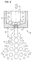
- Figure 2 shows a basic structure of an injection nozzle 10 according to the invention with a superimposed, rapidly changing stroke movement of the nozzle needle.
- FIG. 3 shows a corresponding embodiment with a lifting movement of the (valve) seat of the injection nozzle 20.
- Figures 4 and 5 show in side and front view an embodiment 40 with a device for modulating the effective injection opening.
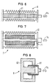
- Figure 6 shows a piezoceramic drive device.
- FIG. 7 shows a magnetostrictive drive device
- FIG. 8 shows an electrodynamic drive device for an injection nozzle according to the invention.
- FIG. 9 shows a complete configuration of an injection nozzle according to the invention.
- 11 denotes the nozzle needle, which also acts as a valve needle. It is located in the nozzle part 12 which has the bore shown as the nozzle opening 13. If the injection nozzle is closed, the front end of the nozzle needle 11 closes the nozzle opening 13. 14 indicates the controllable mobility of the nozzle needle 11.
- fuel indicated at 15 flows along the nozzle needle 11 and within the nozzle part 12 to the nozzle opening 13 in order to form an injection jet with the conical shape having the characteristic 15 shown.
- This jet shape 15 results from the fact that the nozzle needle 11 in the open position is superimposed on the additional alternating stroke movement indicated by 14.
- FIG. 3 reference can largely be made to the details described for FIG. 2. Reference symbols already described for FIG. 2 have the same or at least meaningful meaning in FIG. 3.
- alternating stroke movement is provided for the nozzle part 12 with the nozzle opening 13.
- there is a beam shape which essentially corresponds to that of the embodiment according to FIG. 2.
- FIGS. 4 and 5 show an additional device attached to the nozzle part 12 in the region of the nozzle opening 13.
- FIG. 5 shows an end view belonging to FIG. 4, ie a view against the sprayed jet.
- This additional device 51 of the actual injection nozzle of FIGS. 4 and 5 consist of, for example, four rod-shaped extensions 151, each of which are to be excited to perform lifting movements. These lifting movements are indicated by the individual arrows 54.
- These stroke movements 54 are bending movements of the parts 151.
- These parts 151 form longitudinal guides for the fuel jet 45 emerging from the nozzle opening 13.
- the alternating stroke movements 54 which are transverse to its jet direction, lead to a jet shape as shown at 55.
- the drive element 6 according to FIG. 6 consists of a stack of piezoelectrically excitable disks 61. These disks are provided with flat electrodes, not shown. Such stacks are known in principle and are also supplied with controlled electrical voltage in the present case. In particular, AC voltage is supplied, preferably with such a frequency that leads to resonant oscillatory movements of the lifting movement 114 of the stack or of the drive 6.
- FIG. 7 shows a magnetostrictive embodiment 7 of a drive.
- 71 denotes a rod which can be excited to magnetostriction movements and which is located inside a magnetic field coil 72.
- This magnetic field coil 72 is supplied with electrical voltage, preferably again at a frequency which leads to resonance with a natural oscillation of the rod 71, which leads to a correspondingly large stroke amplitude of the stroke movement 114.
- FIG. 8 shows a drive 8 with plunger coil 81 and pot magnet 82, as is known in principle from loudspeakers. With a corresponding electrical alternating excitation, such a device leads to mechanical stroke movements 114. Resonance excitation can also be effected here.
- FIG. 9 shows an example of an injection nozzle according to the invention.
- the details given for the figures described above have the same meaning in FIG. 9.
- the actuator 91 denotes an actuator, for example a stack consisting of piezoelectric plates. By applying electrical voltage between the connections 92 and 93, this actuator changes its length and thus drives the plunger 94 and the nozzle needle 11 connected to the plunger 94.
- the actuator 91 is used to open and close the valve by moving the valve needle 11.
- the inflow opening of the injection nozzle for the fuel is designated by 95.
- the drive device for the alternating lifting movement to be carried out according to the invention is designated by 96.
- this drive device comprises a plurality of stacks 97 with the electrical connecting lines 98 and 99. Between the connections 98 and 99, the AC drive voltage for this lifting movement is to be applied.
- the outer housing 12 of the injection nozzle (sealed) is divided, this nozzle part 12 guides through the work of the drive 96 perform the alternating stroke movements according to the invention, specifically compared to the nozzle needle which is stationary in this example in the open state. This corresponds to the embodiment variant of the invention already described above in connection with FIG. 3.
Landscapes
- Engineering & Computer Science (AREA)
- Chemical & Material Sciences (AREA)
- Combustion & Propulsion (AREA)
- Mechanical Engineering (AREA)
- General Engineering & Computer Science (AREA)
- Physics & Mathematics (AREA)
- Electromagnetism (AREA)
- Fuel-Injection Apparatus (AREA)
Claims (11)
caractérisée par le fait
caractérisée par le fait
que pour le déclenchement du déplacement alternatif (14,24), une tension alternative (U) peut être appliquée en plus de la tension électrique d'actionnement (Umarche/arrêt) devant être appliquée, pour l'ouverture de la buse.
caractérisée par le fait
que les moyens servant à exécuter le déplacement alternatif (114,14,24,54) forment un système résonnant.
caractérisée par le fait
que les moyens (114,24,54) servant à déclencher le déplacement alternatif sont conçus de manière que le pointeau (11) de la buse exécute ces déplacements alternatifs (14,24,54,114). (Figure 2).
caractérisée par le fait
que les moyens pour déclencher le déplacement alternatif (114,14,24,54) sont agencés de manière qu'une partie du perçage (12,13) de la buse exécute ce déplacement alternatif. (Figure 3).
caractérisée par le fait
qu'il est prévu un déplacement alternatif longitudinal (14,24).
caractérisée par le fait
qu'il est prévu un déplacement alternatif transversal (54).
caractérisée par le fait
que les moyens servant à déclencher le déplacement alternatif comprennent un dispositif d'excitation piézoélectrique (6).
caractérisée par le fait
que les moyens servant à déclencher le déplacement alternatif comprennent un dispositif électrodynamique (8) à un champ magnétique homogène.
caractérisée par le fait
que ces moyens servant à déclencher le déplacement alternatif comprennent un dispositif magnétostrictif (7).
caractérisée par le fait
que ces moyens servant à déclencher le déplacement alternatif comprennent un dispositif électromagnétique (7,8).
Applications Claiming Priority (2)
| Application Number | Priority Date | Filing Date | Title |
|---|---|---|---|
| DE3833093 | 1988-09-29 | ||
| DE3833093A DE3833093A1 (de) | 1988-09-29 | 1988-09-29 | Fuer verbrennungskraftmaschine vorgesehene kraftstoff-einspritzduese mit steuerbarer charakteristik des kraftstoffstrahls |
Publications (2)
| Publication Number | Publication Date |
|---|---|
| EP0361480A1 EP0361480A1 (fr) | 1990-04-04 |
| EP0361480B1 true EP0361480B1 (fr) | 1992-05-20 |
Family
ID=6363986
Family Applications (2)
| Application Number | Title | Priority Date | Filing Date |
|---|---|---|---|
| EP89910599A Expired - Lifetime EP0436586B1 (fr) | 1988-09-29 | 1989-09-28 | Buse d'injection de carburant a jet de carburant reglable |
| EP89117969A Expired - Lifetime EP0361480B1 (fr) | 1988-09-29 | 1989-09-28 | Buse d'injection de combustible à commande de caractéristique du jet de combustible pour moteur à combustion interne |
Family Applications Before (1)
| Application Number | Title | Priority Date | Filing Date |
|---|---|---|---|
| EP89910599A Expired - Lifetime EP0436586B1 (fr) | 1988-09-29 | 1989-09-28 | Buse d'injection de carburant a jet de carburant reglable |
Country Status (6)
| Country | Link |
|---|---|
| US (1) | US5199641A (fr) |
| EP (2) | EP0436586B1 (fr) |
| JP (1) | JPH04501153A (fr) |
| DE (2) | DE3833093A1 (fr) |
| ES (2) | ES2031331T3 (fr) |
| WO (1) | WO1990003512A1 (fr) |
Families Citing this family (67)
| Publication number | Priority date | Publication date | Assignee | Title |
|---|---|---|---|---|
| US5248087A (en) * | 1992-05-08 | 1993-09-28 | Dressler John L | Liquid droplet generator |
| DE4340016A1 (de) * | 1993-11-24 | 1995-06-01 | Bosch Gmbh Robert | Elektromagnetisch betätigbares Kraftstoffeinspritzventil |
| DE4409848A1 (de) * | 1994-03-22 | 1995-10-19 | Siemens Ag | Vorrichtung zur Zumessung und Zerstäubung von Fluiden |
| US5636788A (en) * | 1994-04-01 | 1997-06-10 | City Of Hope | Micro-volume fluid injector |
| JPH0893601A (ja) * | 1994-09-22 | 1996-04-09 | Zexel Corp | 燃料噴射ノズル |
| FR2726603B1 (fr) * | 1994-11-09 | 1996-12-13 | Snecma | Dispositif de controle actif des instabilites de combustion et de decokefaction d'un injecteur de carburant |
| US5836521A (en) * | 1995-03-09 | 1998-11-17 | Dysekompagniet I/S | Valve device with impact member and solenoid for atomizing a liquid |
| US5788154A (en) * | 1996-05-02 | 1998-08-04 | Caterpillar Inc. | Method of preventing cavitation in a fuel injector having a solenoid actuated control valve |
| JP3823391B2 (ja) * | 1996-08-31 | 2006-09-20 | いすゞ自動車株式会社 | エンジンの燃料噴射装置 |
| SE507519C2 (sv) * | 1996-10-16 | 1998-06-15 | Mydata Automation Ab | Anordning för att anbringa ett visköst medium på ett underlag |
| US5855323A (en) * | 1996-11-13 | 1999-01-05 | Sandia Corporation | Method and apparatus for jetting, manufacturing and attaching uniform solder balls |
| JP3404241B2 (ja) * | 1997-02-05 | 2003-05-06 | 明治製菓株式会社 | 油性菓子原料自動スプレー装置 |
| US7320457B2 (en) * | 1997-02-07 | 2008-01-22 | Sri International | Electroactive polymer devices for controlling fluid flow |
| FR2762648B1 (fr) * | 1997-04-25 | 1999-06-04 | Renault | Dispositif d'injection de carburant pour moteur a combustion interne |
| DE19802302A1 (de) | 1998-01-22 | 1999-07-29 | Bosch Gmbh Robert | Piezoelektrischer Aktor |
| DE19921489A1 (de) * | 1999-05-08 | 2000-11-09 | Bosch Gmbh Robert | Brennstoffeinspritzventil |
| US7537197B2 (en) * | 1999-07-20 | 2009-05-26 | Sri International | Electroactive polymer devices for controlling fluid flow |
| DE19936945A1 (de) * | 1999-08-05 | 2001-02-08 | Bosch Gmbh Robert | Verfahren zum Zumessen von Brennstoff- und Brennstoffeinspritzanlage |
| DE19946841A1 (de) * | 1999-09-30 | 2001-05-03 | Bosch Gmbh Robert | Ventil zum Steuern von Flüssigkeiten |
| US6836056B2 (en) | 2000-02-04 | 2004-12-28 | Viking Technologies, L.C. | Linear motor having piezo actuators |
| US6437226B2 (en) | 2000-03-07 | 2002-08-20 | Viking Technologies, Inc. | Method and system for automatically tuning a stringed instrument |
| US6717332B2 (en) | 2000-04-18 | 2004-04-06 | Viking Technologies, L.C. | Apparatus having a support structure and actuator |
| US6548938B2 (en) | 2000-04-18 | 2003-04-15 | Viking Technologies, L.C. | Apparatus having a pair of opposing surfaces driven by a piezoelectric actuator |
| US6363913B1 (en) * | 2000-06-09 | 2002-04-02 | Caterpillar Inc. | Solid state lift for micrometering in a fuel injector |
| US6759790B1 (en) | 2001-01-29 | 2004-07-06 | Viking Technologies, L.C. | Apparatus for moving folded-back arms having a pair of opposing surfaces in response to an electrical activation |
| US6879087B2 (en) * | 2002-02-06 | 2005-04-12 | Viking Technologies, L.C. | Apparatus for moving a pair of opposing surfaces in response to an electrical activation |
| DE10145580A1 (de) * | 2001-09-15 | 2003-04-17 | Bosch Gmbh Robert | Verfahren zum Vermeiden einer Spritzlochinnenverkokung von Spritzlöchern eines Mehrloch-Einspritzventils |
| DE10153708B4 (de) * | 2001-10-31 | 2004-01-29 | Microdrop Gesellschaft für Mikrodosiersysteme mbH | Mikrodosiervorrichtung |
| US6792921B2 (en) * | 2001-12-17 | 2004-09-21 | Caterpillar Inc | Electronically-controlled fuel injector |
| AU2003243697A1 (en) * | 2002-06-21 | 2004-01-06 | Viking Technologies, L.C. | Uni-body piezoelectric motor |
| DE10248106A1 (de) * | 2002-10-15 | 2004-05-19 | Bühler AG | Vibrodüsen-Anordnung |
| US6811093B2 (en) * | 2002-10-17 | 2004-11-02 | Tecumseh Products Company | Piezoelectric actuated fuel injectors |
| JP4500900B2 (ja) * | 2002-10-24 | 2010-07-14 | 小川 秀和 | 整復装置および衣類 |
| US6991612B2 (en) * | 2003-02-03 | 2006-01-31 | The Seaberg Company, Inc. | Orthopedic splints |
| GB2416425B (en) | 2003-04-04 | 2007-01-03 | Viking Technologies Lc | Apparatus and process for optimizing work from a smart material actuator product |
| FR2888889B1 (fr) * | 2005-07-20 | 2007-08-31 | Renault Sas | Dispositif d'injection de carburant pour moteur a combustion interne |
| WO2007039677A1 (fr) * | 2005-10-03 | 2007-04-12 | Renault S.A.S. | Dispositif de mise en vibration cyclique d'une buse injecteur |
| US7810743B2 (en) | 2006-01-23 | 2010-10-12 | Kimberly-Clark Worldwide, Inc. | Ultrasonic liquid delivery device |
| US7819335B2 (en) | 2006-01-23 | 2010-10-26 | Kimberly-Clark Worldwide, Inc. | Control system and method for operating an ultrasonic liquid delivery device |
| US7424883B2 (en) | 2006-01-23 | 2008-09-16 | Kimberly-Clark Worldwide, Inc. | Ultrasonic fuel injector |
| US7963458B2 (en) | 2006-01-23 | 2011-06-21 | Kimberly-Clark Worldwide, Inc. | Ultrasonic liquid delivery device |
| US7744015B2 (en) | 2006-01-23 | 2010-06-29 | Kimberly-Clark Worldwide, Inc. | Ultrasonic fuel injector |
| US7735751B2 (en) | 2006-01-23 | 2010-06-15 | Kimberly-Clark Worldwide, Inc. | Ultrasonic liquid delivery device |
| US8028930B2 (en) | 2006-01-23 | 2011-10-04 | Kimberly-Clark Worldwide, Inc. | Ultrasonic fuel injector |
| US8191732B2 (en) | 2006-01-23 | 2012-06-05 | Kimberly-Clark Worldwide, Inc. | Ultrasonic waveguide pump and method of pumping liquid |
| DE102006012389A1 (de) * | 2006-03-17 | 2007-09-20 | MAX-PLANCK-Gesellschaft zur Förderung der Wissenschaften e.V. | Verfahren und Vorrichtung zur Zerstäubung einer Flüssigkeit |
| EP1860317A1 (fr) * | 2006-05-23 | 2007-11-28 | Keihin Corporation | Dispositif d'injection de carburant, dispositif de commande d'injection de carburant et procédé de commande du dispositif de commande d'injection |
| JP4535032B2 (ja) * | 2006-07-04 | 2010-09-01 | 株式会社デンソー | 燃料噴射制御装置 |
| DE102007016626A1 (de) * | 2007-04-05 | 2008-10-16 | Continental Automotive Gmbh | Einspritzventil und Verfahren und Vorrichtung zum Betreiben des Einspritzventils |
| DE102007016725B3 (de) * | 2007-04-07 | 2008-01-17 | Dräger Medical AG & Co. KG | Elektrodynamischer Antrieb für ein Dosierventil |
| FR2916810B1 (fr) * | 2007-05-31 | 2009-08-28 | Renault Sas | Dispositif d'injection de fluide |
| FR2918122B1 (fr) * | 2007-06-27 | 2009-08-28 | Renault Sas | Dispositif d'injection de fluide. |
| JP5602626B2 (ja) | 2007-06-29 | 2014-10-08 | アーティフィシャル マッスル,インク. | 感覚性フィードバック用途のための電気活性ポリマートランスデューサー |
| US20090057438A1 (en) * | 2007-08-28 | 2009-03-05 | Advanced Propulsion Technologies, Inc. | Ultrasonically activated fuel injector needle |
| US7533830B1 (en) * | 2007-12-28 | 2009-05-19 | Kimberly-Clark Worldwide, Inc. | Control system and method for operating an ultrasonic liquid delivery device |
| FR2929656A1 (fr) * | 2008-04-03 | 2009-10-09 | Renault Sas | Injecteur de fluide, et procede de commande d'un tel injecteur |
| EP2239793A1 (fr) | 2009-04-11 | 2010-10-13 | Bayer MaterialScience AG | Montage de film polymère électrique commutable et son utilisation |
| NL1037570C2 (en) * | 2009-12-18 | 2011-06-21 | Heinmade B V | A device for dispensing a substance. |
| JP2014513510A (ja) | 2011-03-01 | 2014-05-29 | バイエル・インテレクチュアル・プロパティ・ゲゼルシャフト・ミット・ベシュレンクテル・ハフツング | 変形可能なポリマー装置及び変形可能なポリマーフィルムを作るための自動化された製造プロセス |
| KR20140019801A (ko) | 2011-03-22 | 2014-02-17 | 바이엘 인텔렉쳐 프로퍼티 게엠베하 | 전기활성 중합체 작동기 렌티큘라 시스템 |
| US20130068200A1 (en) * | 2011-09-15 | 2013-03-21 | Paul Reynolds | Injector Valve with Miniscule Actuator Displacement |
| US9876160B2 (en) | 2012-03-21 | 2018-01-23 | Parker-Hannifin Corporation | Roll-to-roll manufacturing processes for producing self-healing electroactive polymer devices |
| KR20150031285A (ko) | 2012-06-18 | 2015-03-23 | 바이엘 인텔렉쳐 프로퍼티 게엠베하 | 연신 공정을 위한 연신 프레임 |
| WO2014066576A1 (fr) | 2012-10-24 | 2014-05-01 | Bayer Intellectual Property Gmbh | Diode polymère |
| US9506429B2 (en) | 2013-06-11 | 2016-11-29 | Cummins Inc. | System and method for control of fuel injector spray using ultrasonics |
| US20150315981A1 (en) * | 2014-05-02 | 2015-11-05 | General Electric Company | Fuel supply system |
| DE102016125156B4 (de) | 2015-12-23 | 2023-08-10 | Volkswagen Aktiengesellschaft | Verfahren zur Reinigung eines Kraftstoff-Einspritzventils mittels Ultraschallanregung |
Family Cites Families (30)
| Publication number | Priority date | Publication date | Assignee | Title |
|---|---|---|---|---|
| DE1947329A1 (de) * | 1969-09-18 | 1971-03-25 | Szekessy Istvan Dipl Ing | Vorrichtung zum dosierten Verteilen von Fluessigkeiten,insbesondere Zerstaeuber |
| GB1344635A (en) * | 1970-05-14 | 1974-01-23 | Plessey Co Ltd | Transducers |
| GB1515002A (en) * | 1975-03-05 | 1978-06-21 | Plessey Co Ltd | Fuel atomizers |
| CH557698A (fr) * | 1972-08-23 | 1975-01-15 | Ciba Geigy Ag | Procede de fractionnement d'un liquide, dispositif mettant en oeuvre ce procede et application de ce procede a la granulation d'un produit liquefie au prealable. |
| US4211199A (en) * | 1972-09-29 | 1980-07-08 | Arthur K. Thatcher | Computer controlled sonic fuel system |
| NL7301617A (fr) * | 1973-02-06 | 1974-08-08 | ||
| DE2412490A1 (de) * | 1974-03-15 | 1975-09-25 | Kunz Dieter | Einspritz- und vernebelungskopf |
| DE2449379A1 (de) * | 1974-10-17 | 1976-04-29 | Rau Swf Autozubehoer | Einspritzduese fuer oel- und gasbefeuerte oefen |
| GB2012357B (en) * | 1978-01-17 | 1982-03-24 | Plessey Co Ltd | Low pressure fuel injection system |
| IT1121343B (it) * | 1978-06-24 | 1986-04-02 | Plessey Handel Investment Ag | Iniettore di carburante |
| DE2904861C3 (de) * | 1979-02-09 | 1981-08-06 | Philips Patentverwaltung Gmbh, 2000 Hamburg | Piezoelektrischer Flüssigkeitszerstäuber |
| DE3010178C2 (de) * | 1980-03-17 | 1985-10-03 | Kraftwerk Union AG, 4330 Mülheim | Mit einem Schnellschlußventil ausgerüstete Schlitzdüse zur Herbeiführung impulsartiger Gasströmungen |
| DE3010985A1 (de) * | 1980-03-21 | 1981-10-01 | Siemens AG, 1000 Berlin und 8000 München | Kraftstoff-einspritzduese mit zusaetzlicher kraftstoff-zerstaeubung |
| FR2488655A2 (fr) * | 1980-08-18 | 1982-02-19 | Rockwell International Corp | Injecteur de carburant equipe d'un clapet de retenue a vibrations ultra-sonores, notamment pour moteur diesel |
| GB2096021B (en) * | 1981-03-24 | 1985-01-23 | British Hydromechanics | High pressure liquid jetting guns |
| US4421280A (en) * | 1981-09-28 | 1983-12-20 | The Bendix Corporation | Fuel injector |
| US4535743A (en) * | 1983-04-15 | 1985-08-20 | Nippon Soken, Inc. | Fuel injection apparatus for an internal combustion engine |
| JPS6022066A (ja) * | 1983-07-19 | 1985-02-04 | Hitachi Metals Ltd | 燃料噴射器 |
| DE3344229A1 (de) * | 1983-12-07 | 1985-06-20 | Pierburg Gmbh & Co Kg, 4040 Neuss | Elektromagnetisches brennstoffeinspritzventil |
| US4635849A (en) * | 1984-05-03 | 1987-01-13 | Nippon Soken, Inc. | Piezoelectric low-pressure fuel injector |
| FR2567238B1 (fr) * | 1984-07-06 | 1986-12-26 | Sibe | Electrovanne a effet piezo-electrique |
| JPS6189975A (ja) * | 1984-10-09 | 1986-05-08 | Diesel Kiki Co Ltd | 内燃機関の燃料噴射ノズル装置 |
| US4726523A (en) * | 1984-12-11 | 1988-02-23 | Toa Nenryo Kogyo Kabushiki Kaisha | Ultrasonic injection nozzle |
| DE3501077A1 (de) * | 1985-01-15 | 1986-07-17 | Kernforschungszentrum Karlsruhe Gmbh, 7500 Karlsruhe | Pulsventil |
| DE3517257A1 (de) * | 1985-05-13 | 1987-01-15 | Vdo Schindling | Elektrisch betaetigbares kraftstoffeinspritzventil fuer brennkraftmaschinen |
| DE3533085A1 (de) * | 1985-09-17 | 1987-03-26 | Bosch Gmbh Robert | Zumessventil zur dosierung von fluessigkeiten oder gasen |
| DE3533975A1 (de) * | 1985-09-24 | 1987-03-26 | Bosch Gmbh Robert | Zumessventil zur dosierung von fluessigkeiten oder gasen |
| JPH065060B2 (ja) * | 1985-12-25 | 1994-01-19 | 株式会社日立製作所 | 内燃機関用超音波式燃料微粒化装置の駆動回路 |
| JPS63143361A (ja) * | 1986-12-04 | 1988-06-15 | Aisan Ind Co Ltd | インジエクタ用バルブの制御方法 |
| US4972996A (en) * | 1989-10-30 | 1990-11-27 | Siemens-Bendix Automotive Electronics L.P. | Dual lift electromagnetic fuel injector |
-
1988
- 1988-09-29 DE DE3833093A patent/DE3833093A1/de not_active Withdrawn
-
1989
- 1989-09-28 ES ES198989117969T patent/ES2031331T3/es not_active Expired - Lifetime
- 1989-09-28 EP EP89910599A patent/EP0436586B1/fr not_active Expired - Lifetime
- 1989-09-28 JP JP1509929A patent/JPH04501153A/ja active Pending
- 1989-09-28 WO PCT/DE1989/000610 patent/WO1990003512A1/fr not_active Ceased
- 1989-09-28 US US07/671,881 patent/US5199641A/en not_active Expired - Fee Related
- 1989-09-28 DE DE8989910599T patent/DE58902915D1/de not_active Expired - Fee Related
- 1989-09-28 EP EP89117969A patent/EP0361480B1/fr not_active Expired - Lifetime
- 1989-09-29 ES ES8903305A patent/ES2015816A6/es not_active Expired - Lifetime
Also Published As
| Publication number | Publication date |
|---|---|
| ES2015816A6 (es) | 1990-09-01 |
| EP0361480A1 (fr) | 1990-04-04 |
| EP0436586B1 (fr) | 1992-12-02 |
| ES2031331T3 (es) | 1992-12-01 |
| WO1990003512A1 (fr) | 1990-04-05 |
| JPH04501153A (ja) | 1992-02-27 |
| US5199641A (en) | 1993-04-06 |
| DE3833093A1 (de) | 1990-04-12 |
| EP0436586A1 (fr) | 1991-07-17 |
| DE58902915D1 (de) | 1993-01-14 |
Similar Documents
| Publication | Publication Date | Title |
|---|---|---|
| EP0361480B1 (fr) | Buse d'injection de combustible à commande de caractéristique du jet de combustible pour moteur à combustion interne | |
| DE60025530T2 (de) | Brennstoffeinspritzvorrichtung für brennkraftmaschine | |
| EP0036617A2 (fr) | Injecteur de combustible avec atomisation ultérieure du combustible | |
| DE2650415C3 (de) | Vorrichtung zum Einspritzen und Zerstäuben von Krafstoff | |
| DE68924202T2 (de) | Überschall-Kraftstoff-Einspritzdüse. | |
| DE3124854C2 (de) | Hochdruckeinspritzsystem mit Ultraschall-Zerstäubung | |
| DE3132463A1 (de) | Ultraschallventil fuer einen dieseloel-injektor | |
| DE3828591C2 (de) | Einspritzventil für Brennkraftmaschinen | |
| DE20122813U1 (de) | Modulare Ultraschall-Kraftstoffeinspritzdüse mit einem keramischen Ventilkörper | |
| DE2348395A1 (de) | System zur einfuehrung von brennstoff in eine verbrauchereinrichtung | |
| DE2701422A1 (de) | Brennstoffeinspritzvorrichtung | |
| DE69613141T2 (de) | Kraftstoffeinspritzkolbenmotor | |
| DE1476168C3 (de) | Vorrichtung für kontinuierliche Kraftstoffeinspritzung in das Ansaugrohr von Brennkraftmaschinen | |
| DE3122295A1 (de) | Ultraschall-brennstoffinjektor fuer dieselmotoren | |
| DE60124630T2 (de) | Brennstoffeinspritzvorrichtung für eine Brennkraftmaschine | |
| DE2925108A1 (de) | Einspritzvorrichtung | |
| DE4022226A1 (de) | Brennstoffeinspritzvorrichtung fuer luftverdichtende brennkraftmaschinen | |
| DE19516245C2 (de) | Verfahren zum Steuern einer mehrphasigen Einspritzung eines direkt einspritzenden Dieselmotors | |
| DE3627325A1 (de) | Elektrische druckumwandlungs-steuervorrichtung | |
| DE3614115A1 (de) | Kraftstoffspeisung fuer brennkraftmaschine | |
| DE60104210T2 (de) | Kraftstoffeinspritzvorrichtung für eine brennkraftmaschine | |
| DE102016125156B4 (de) | Verfahren zur Reinigung eines Kraftstoff-Einspritzventils mittels Ultraschallanregung | |
| DE102007026946B4 (de) | Verfahren und Vorrichtung zum Betreiben eines Einspritzventils, Computerprogramm und Einspritzventil | |
| WO2001011224A1 (fr) | Procede de distribution dosee de carburant et installation d'injection de carburant | |
| EP1346149A1 (fr) | Soupape d'injection de carburant |
Legal Events
| Date | Code | Title | Description |
|---|---|---|---|
| PUAI | Public reference made under article 153(3) epc to a published international application that has entered the european phase |
Free format text: ORIGINAL CODE: 0009012 |
|
| AK | Designated contracting states |
Kind code of ref document: A1 Designated state(s): ES |
|
| 17P | Request for examination filed |
Effective date: 19900427 |
|
| 17Q | First examination report despatched |
Effective date: 19910603 |
|
| GRAA | (expected) grant |
Free format text: ORIGINAL CODE: 0009210 |
|
| AK | Designated contracting states |
Kind code of ref document: B1 Designated state(s): ES |
|
| PGFP | Annual fee paid to national office [announced via postgrant information from national office to epo] |
Ref country code: ES Payment date: 19920917 Year of fee payment: 4 |
|
| REG | Reference to a national code |
Ref country code: ES Ref legal event code: FG2A Ref document number: 2031331 Country of ref document: ES Kind code of ref document: T3 |
|
| PLBE | No opposition filed within time limit |
Free format text: ORIGINAL CODE: 0009261 |
|
| STAA | Information on the status of an ep patent application or granted ep patent |
Free format text: STATUS: NO OPPOSITION FILED WITHIN TIME LIMIT |
|
| 26N | No opposition filed | ||
| PG25 | Lapsed in a contracting state [announced via postgrant information from national office to epo] |
Ref country code: ES Free format text: LAPSE BECAUSE OF THE APPLICANT RENOUNCES Effective date: 19930929 |
|
| REG | Reference to a national code |
Ref country code: ES Ref legal event code: FD2A Effective date: 19991007 |