EP0361826A2 - Halterung eines Thermo-Druckkopfes und Thermo-Druckverfahren - Google Patents
Halterung eines Thermo-Druckkopfes und Thermo-Druckverfahren Download PDFInfo
- Publication number
- EP0361826A2 EP0361826A2 EP89309722A EP89309722A EP0361826A2 EP 0361826 A2 EP0361826 A2 EP 0361826A2 EP 89309722 A EP89309722 A EP 89309722A EP 89309722 A EP89309722 A EP 89309722A EP 0361826 A2 EP0361826 A2 EP 0361826A2
- Authority
- EP
- European Patent Office
- Prior art keywords
- thermal head
- platen roller
- thermal
- head
- supporting
- Prior art date
- Legal status (The legal status is an assumption and is not a legal conclusion. Google has not performed a legal analysis and makes no representation as to the accuracy of the status listed.)
- Granted
Links
Images


Classifications
-
- B—PERFORMING OPERATIONS; TRANSPORTING
- B41—PRINTING; LINING MACHINES; TYPEWRITERS; STAMPS
- B41J—TYPEWRITERS; SELECTIVE PRINTING MECHANISMS, i.e. MECHANISMS PRINTING OTHERWISE THAN FROM A FORME; CORRECTION OF TYPOGRAPHICAL ERRORS
- B41J25/00—Actions or mechanisms not otherwise provided for
- B41J25/304—Bodily-movable mechanisms for print heads or carriages movable towards or from paper surface
- B41J25/312—Bodily-movable mechanisms for print heads or carriages movable towards or from paper surface with print pressure adjustment mechanisms, e.g. pressure-on-the paper mechanisms
Definitions
- the present invention relates to a thermal printing system,and more particularly,to a thermal head supporting means for a thermal printing system,having features of light weight,flexibility,ready for adjustment and is especially suitable for an open-frame type thermal printing system, namely,such one the frame of which is separated into two pieces of an upper frame and a lower frame,and the former is hinged onto the latter so as to be swingably movable upward and downward and,further,superior in accuracy of printing.
- a thermal printing system functions to print alphanumeric and or image information on a paper sheet by melting thermaly fusible ink applied on the surface of a thermal printing ribbon or ribbons,by means of passing both a paper sheet and thermal printing ribbon being overlapped, through a gap between a thermal head and a platen roller,and it has various features such as small size,light weight yet allowing multi-colour printing in a quite a simple way.
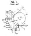
- Fig.1 is a side view showing the structural feature of the thermal head supporting means of a conventional general type thermal printing system.
- a thermal head 50 held by a head holder 31 is depressed on a platen 21, and a thermal printing paper and a printing ribbon being overlapped with each other are passed through the gap between these two members and further fed upward by the platen roller 21.
- the head holder 31 is disposed around a head holder shaft 31a rotatably received by the same frame carrying said platen roller 21 and is pulled rightward by a depression spring 7 so that the thermal head 50 can be depressed upon the platen roller 21.
- the extent of the depression force mentioned above can be adjusted by an adjustment screw 37 disposed on both sides of the head holder 31 so as to be uniform in the direction transverse to the direction of the paper sheet 5.
- numeral38 denotes a sensor for detecting the position of a printing ribbon 4
- numeral 39 denotes a sensor holder
- numeeral 37′ is a locking screw for fixing the adjustment screw 37
- 41 denotes a heat sink for radiating heat given from the thermal head 50.
- Fig.2 is a schematic side view showing the main portion of the above-mentioned thermal head supporting means,wherein a rolled paper sheet 5 paid off from a roller R1 is fed via a roller R2 onto the outer periphery of a platen roller 21 and then fed leftward by turning back along the outer periphery of the platen roller 21.
- an ink ribbon 4 applied with thermally fusible printing ink is also paid off from a roller R3 and overlapped with the paper sheet 5 on the outer periphery of the platen roller 21 and then taken up by a take-up roller 39.
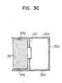
- the thermal head supporting means as explained above and shown in Fig. 3A and 3B is composed of following three main components,:
- the head holder 31 can be swung in a see-saw like motion around the hinge shaft 40 via the rolling bearings 35.
- the depression force exerted between the platen roller 21 and the thermal head can be made uniform over the entire width of the printing paper,and by virtue of of this prior type thermal head supporting means,an entirely uniform depression force can be assured between the thermal head and the platen roller with no particular adjustment.
- Both side walls 32a,32b and a transverse connecting bar 32c of the frame member 32 are integrally formed by such means as aluminum allow die casting technique or the like, and these members themselves have a considerable volume together with a heavy weight.
- a supporting member 33 of considerably large volume is assembled with both the side walls 32a and 32b at the opened left side end by means of a hinge shaft 40 which passing through the two side walls 32a,32b and the supporting member 33 interposed between the two side frames.
- Fig.3C is a schematic plan view showing general shade and construction of the supporting means as mentioned above.
- the present invention aims to provide a thermal head supprting means for a thermal printing system which satisfy the requirement of small volume,light weight,readily fabricable construction and uniform depression force between the thermal head and the platen roller with no particular adjustment
- the primary object of this invention to provide an improved thermal head supporting means which can be fabricated as a small sized and light weight member by a simple process such as punching of thin metal plate.
- Another object of the present invention is to provide a thermal head supporting means which can exert uniform force of depression between the thermal head and the platen roller of a thermal printing system.
- Yet another object of the present invention is to provide a thermal head supporting means in which the depression force between the thermal head and the platen roller is applied on the central part of a supporting shaft in a range as small as possible to obviate any wavy movement of the thermal head and to allows the thermal head to separate from the platen roller when the printing system is not under its printing operation.
- each of the parts or components constitutes the thermal head supporting means according to the present invention is designed to be small in size,thin thickness and having such a shade as can be readily fabricated by press forming of metal sheet or by moulding plastic material,in addition,the position of the rotary shaft at which the thermal head supporting means is attached to the shaft is placed to the central part of the rotary shaft with the intention to adopt one point central support type suspension.
- Depression of a thermal head against a platen roller is performed by urging by cam action a thermal head urging lever,having a length considerably shorter in axial direction,thereby the depression can be applied via a depression spring disposed at the central part of and normal to the aforesaid rotary shaft.
- the thermal head is constructed to be moved away from the rotary shaft of the platen roller when the thermal printing system is out of printing operation.
- a thermal head supporting means has such features that it can be made as a very very light weight member together with its one point central supporting type construction and thereby can assure uniform depression force against the platen roller,and thus it can be used as a supporting means especially suitable for an open frame type thermal printing system wherein its upper frame can be swung upward or swung down to take its set posposition to its mating lower frame.
- the supporting plate for supporting a thermal head is held at a predetermined position at the central part of a supporting shaft and is normally urged by a spring to let the thermal head to effect swing motion,so there is no fear that any wavy motion oh the thermal head would take place.
- the supporting plate is formed with a pair of oblong through holes each being normal to the supporting shaft and directed to a cam shaft for urging the thermal head so as to allow fine adjustment of the thermal head in a direction normal to the platen shaft.
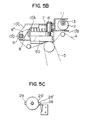
- Fig.4 is a schematic side view showing an open-frame type thermal printing system equipped with a thermal head supporting means according to the present invention.
- Numeral 10 in the drawing shows an entire part of the thermal head supporting means almost the whole portion of which shown by dotted lines,in which 21 is a platen roller, 14 is a head guide post,which slidably receives a thermal head 50 through a pair of ball bearings 15,relative to a pair of oblong holes 14′ formed almost vertically on each of a pair of upper side frames 18 and 19.
- the pair of oblong holes 14′ are formed to have a length corresponding to the swing stroke of the head guide post 14 actuated by a head depressing cam,which will be explained later.
- Numerals 25 and 26,respectively, is a lower side frame at the right or the left side of the printing system
- numerals 27 and 27′ is a upwardly opened recess for adapting a ball bearing which journally receives each of the guide post 14 when the upper side frames 18 and 19 are swung down to be coupled with the inside of the lower side frames 25 and 26.
- Fig.5A is a plan view of the thermal head supporting means 10.
- numeral 9 is a head supporting shaft which acts as a swing shaft through a thermal head urging lever explained later,so as to urge the thermal head 50 against the platen roller 21 or to make it leave away from the platen roller 21 by the aid of a thermal head retracting plate 11,and the swing shaft 9 is gassed through both right and left upper side frames 18 and 19 and is further fixed,at each axial ends,to each upper side frame by a set screw.
- Numeral 8 in the drawings is a thermal head supporting plate having L-shape in cross section and fabricated of a metal plate and having two flat portions each being bent perpendicular to the other,and one of the flat portion 8′is secured along the rear face of the thermal head 50 by a set screw or screws,while the other flat portion 8 ⁇ is formed with an oblong through hole 8′′′,through which the head supporting shaft 9 can pass and being parallel to the side face of the thermal head 50.
- the thermal head supporting shaft 9 in assembly is passed through the oblong hole 8′′′ and the flat portion 8 ⁇ is resiliently positioned being urged by a spring 24 aginst a fixed stopper ring 24′ attached on the supporting shaft 9,thereby the flat portion 8"of the thermal head supporting plate plays a role as an arm for swingably holding the thermal head 50.
- the fixed stopper ring 24′ is composed of a pair of rings,and if one ring(left side one in the drawing) is located at the center of the supporting shaft 9,the thermal head supporting plate 8 could be held at the central position of the thermal head supporting shaft 9,and thus any side play, namely,any wavy motion of the thermal head along the head supporting shaft leading to slipping off of the printed dots can be prevented from occuring.
- Numeral 10′ denotes a thermal head urging lever as a formed member of thin thickness that can be fabricated either by punching and bending a metal plate or by molding plastic material,which lever has a configuration alike an inverted thick and short " T " seen in plan view and being composed of three parts 10′A,10′B and 10′C as explained later.
- 10′A is a top plate having almost a rectangular contour and the interior part of which is punched out to reduce its weight
- 10′B is a front portion formed by being bent lowered at the front end of the top plate and is bent again to project forward
- 10′C is a side peripheral portion bent downward to depend from the side periphery of the top plate 10′A with its rear portion slantly descending rearward to constitute a connecting arm 10′D.
- Numeral 11 is a thermal head retracting plate tightly secured,by a set screw or by spot welding,to the top plate 10′A at the portion adjacent to its forward end and is raised further by bending upward at right angle by a predetermined height at the portion slightly before the forward end of the top plate,and further bent at right angle to extend forward.
- This thermal head retracting plate is far smaller in size and much lighter in weight as compared with the above-mentioned thermal head urging lever 10′.
- Parallel distance between the forward end portion of the thermal head urging lever 10′B and the thermal head retraccting plate 11 is set up corresponding to the diameter of the head urging cam 12 to be slidably disposed between these two members,thereby the difference between the maximum diameter portion and the minimum diameter portion of the head urging cam determines the swing strokle of the thermal head 50.
- Numeral 13 is a thermal head urging cam shaft extending between the upper side frames 18 and 19 at both sides of the device and is driven by a motor 16 through a set of gear 17 to rotate the head urging cam 12.
- Numeral 6 in Figs.5A and 5B denotes a spring guide cost inserted through the hole opened at the transversely central cart near the frontmost end of the top plate 10′ of the thermal head urging lever 10′,which guide post consists of a head formed with a slot for receiving the tip end of a screw driver for turning,a neck extending to the top face of the thermal head 50 and a threaded portion under the neck threaded with male thread(s)which threadably engages the female thread formed on the thermal head,and thereby the extent of projection of the spring guide post beyond the top plate 10′ can be adjusted.
- thermo head urging spring 7 is a thermal head urging spring disposed around the above-mentioned spring guide post 6 and in a gap between the top face of the thermal head 50 and the reverse face of the thermal head urging lever 10′,and thus it acts to resiliently transmit an urging force imparted by the thermal head urging lever 10′to the thermal head 50,in addition spring force of the urging spring 7 can be adjusted by adjusting the amount of the projection of the unthreaded shank of the spring guide post 6.
- thermal head urging cam 12 When it becomes necessary to depress the thermal head 50 against the platen roller 21 due to an applied signal instructing the start of printing Y(yellow)colour,the thermal head urging cam 12 is rotated by a motor 16 to depress the thermal head urging lever 10′,thereby the thermal head is depressed against the outer surface of the platen roller 21,then the microswitch 28 is turned ON by the switch cam 29 and stops the rotation of the thermal head urging cam 12.
- the thermal head retracting plate 11 When it becomes necessary after having finished the printing Y(yellow),to retract the thermal head 50 away from the platen roller 21 immediately before rolling back the paper sheet ready for subsequent M(magenta) printing,the thermal head retracting plate 11 is raised upward by rotating the motor to retract the thermal head,then the thermal head urging cam 12 is stopped by the micro switch 28′.
- Rotation of the thermal head urging cam 12 accompanies rotation of the swith cam 29 and allows subsequent rotation of the thermal head urging cam for next printing.
- the thermal head 50 is secured,at the central part of its rear end face,to one flat face of the thermal head supporting plate 8,while the other flat face of the head supporting plate 8 is resiliently and swingably supported with respect to the head supporting post 9 which passes through the oblong hole 8′′′ formed through the flat face of the head supporting plate 8,as a consequence the thermal head 50 is supported in a so-called one-point central support type manner.
- thermal head supporting plate 8 is allowed for effecting fine adjustment with respect to the supporting shaft 9 in a direction normal to the axis of the supporting shaft.
- thermal head 50 and sub-assebly of thethermal head urging lever 10′and the thermal head rettracting plate 11 (referred to"head urging lever assembly")is coupled together,then the head supporting shaft 9 is passed through and the head urging cam is positioned between the head urging lever 10′ and the head retracting plate 11,thus the thermal head 50 and the head urging lever assembly as a whole functions as a thermal head depressing unit.
- thermal head urging unit Since all of the thermal head supporting plate,the head urging lever and the head retracting plate constituting a thermal head urging unit are fabricated by press working of considerably thin metal sheets or plates,and yet the transverse width of the thermal head urging lever is less than one half the spacing between two side frames and the central portion of the urging lever is punched out,the thermal head urging unit is remarkably smaller in size and light in weight as compared with thermal head holders of prior art.
- thermal head urging unit of this type is tightly coupled to the head supporting shaft at 9 at its axial center by the head supporting plate under a spring force and in a one-point central support type manner,there is no fear that the point of supporting should shift to cause wavy motion.
- holes formed in the side frames at right and left side through which the head support shaft and the head urging cam shaft are passed can be formed by means of precise pressing technique,so the positioning of these holes can be sequred correctly,so the perpendicularity of both the supporting shaft 9 and the head urging cam shaft 13 with respect to both side frames,namely,the parallelism of these two shafts also can be assured.
- the thermal head supporting means of the present invention is positioned and adjusted such that the relative position of the heating element of the thermal head and the platen roller in the direction normal to the axis of the platen,and the parallelism of these two members can be assured,in a state where the two upper side frames 18 and 19 are swung down and coupled to the lower side frame 25 and 26,the force of depression applied to the thermal head as shown in the above-mentioned embodiment is restricted in an axial width of the top face 10'A of the thermal hed urging lever 10′,which is is really a short range less than one half of the length of span between the two upper side frames 18 and 19,therefore it does not restrain the overall length of the thermal head.
- thermal head 50 As the thermal head 50 is received at its both axial ends,by the head guide post 14 and via a pair of ball bearrings 15 in the oblong holes 14′,respectively,sufficient freedom is given for machining,assembling and adjustment.
- the thermal head urging cam further rotates,the head retracting plate is gradualy raised and the thermal head urging unit is moved to leave away from the platen roller,on the other hand,when the minimum diameter portion of the thermal head urging cam engages the head retracting plate 11,the distance of the retracted thermal head from the platen roller becomes maximum.
Landscapes
- Common Mechanisms (AREA)
- Electronic Switches (AREA)
Applications Claiming Priority (2)
| Application Number | Priority Date | Filing Date | Title |
|---|---|---|---|
| JP63239066A JP2560448B2 (ja) | 1988-09-26 | 1988-09-26 | 熱転写記録装置のサーマルヘッド保持構造 |
| JP239066/88 | 1988-09-26 |
Publications (3)
| Publication Number | Publication Date |
|---|---|
| EP0361826A2 true EP0361826A2 (de) | 1990-04-04 |
| EP0361826A3 EP0361826A3 (en) | 1990-12-27 |
| EP0361826B1 EP0361826B1 (de) | 1995-03-22 |
Family
ID=17039352
Family Applications (1)
| Application Number | Title | Priority Date | Filing Date |
|---|---|---|---|
| EP89309722A Expired - Lifetime EP0361826B1 (de) | 1988-09-26 | 1989-09-25 | Halterung eines Thermo-Druckkopfes und Thermo-Druckverfahren |
Country Status (5)
| Country | Link |
|---|---|
| US (1) | US4962392A (de) |
| EP (1) | EP0361826B1 (de) |
| JP (1) | JP2560448B2 (de) |
| CA (1) | CA1316756C (de) |
| DE (1) | DE68921827T2 (de) |
Cited By (7)
| Publication number | Priority date | Publication date | Assignee | Title |
|---|---|---|---|---|
| EP0515224A3 (en) * | 1991-05-24 | 1993-09-29 | Mitsubishi Denki Kabushiki Kaisha | Paper feed for printing apparatus |
| EP0555556A3 (en) * | 1992-01-10 | 1993-12-29 | Markem Corp | Multi-color thermal transfer printer with arcuate print head arrangement and printing pressure adjustment |
| US5921687A (en) * | 1991-05-24 | 1999-07-13 | Mitsubishi Denki Kabushiki Kaisha | Printing apparatus |
| FR2783458A1 (fr) * | 1998-09-17 | 2000-03-24 | Samsung Electro Mech | Dispositif pour reguler la pression des tetes dans une imprimante miniature |
| WO2004012943A3 (en) * | 2002-08-06 | 2004-04-08 | Markem Tech Ltd | Printing apparatus and methods |
| WO2013070727A1 (en) * | 2011-11-07 | 2013-05-16 | Zih Corp. | Media processing device with enhanced media and ribbon loading and unloading features |
| US9744784B1 (en) | 2016-02-05 | 2017-08-29 | Zih Corp. | Printhead carriers and adapters |
Families Citing this family (17)
| Publication number | Priority date | Publication date | Assignee | Title |
|---|---|---|---|---|
| US5106213A (en) * | 1990-06-01 | 1992-04-21 | Smith Corona Corporation | Thermal print head control mechanism |
| US5238314A (en) * | 1990-07-13 | 1993-08-24 | Tokyo Electric Co., Ltd. | Transfer printer with ribbon lock |
| US5180236A (en) * | 1990-07-13 | 1993-01-19 | Tokyo Electric Co., Ltd. | Transfer printer |
| US5092688A (en) * | 1990-08-31 | 1992-03-03 | Cognitive Solutions, Inc. | Portable barcode printer |
| DE4224533A1 (de) * | 1991-07-25 | 1993-01-28 | Kanzaki Paper Mfg Co Ltd | Thermo-drucker |
| US5176458A (en) * | 1992-06-08 | 1993-01-05 | Eastman Kodak Company | Multiple position thermal printer head mechanism which is disturbance insensitive |
| US5440328A (en) * | 1992-10-05 | 1995-08-08 | Atlantek, Inc. | Single-pass multi-color thermal printer |
| US5570961A (en) * | 1993-05-31 | 1996-11-05 | Victor Company Of Japan, Ltd. | Color printer feeding mechanism |
| US5541635A (en) * | 1994-03-18 | 1996-07-30 | Mettler-Toledo, Inc. | Printer mechanism |
| DE69710634D1 (de) * | 1996-05-09 | 2002-04-04 | Agfa Gevaert Nv | Thermische Druckeinrichtung mit Druckkopfeinstellung |
| DE19720671A1 (de) * | 1996-05-29 | 1997-12-04 | Eastman Kodak Co | Verstellbare Druckkopfhalterung für Vorlagenabbildungsgerät |
| US6261009B1 (en) | 1996-11-27 | 2001-07-17 | Zih Corporation | Thermal printer |
| JP4006701B2 (ja) * | 2003-07-28 | 2007-11-14 | 船井電機株式会社 | 熱転写プリンタ |
| US7355613B2 (en) * | 2005-08-03 | 2008-04-08 | Carestream Health, Inc. | Thermal recording system employing adjustable head pressure |
| JP4824368B2 (ja) * | 2005-08-31 | 2011-11-30 | 株式会社サトー | 印字ユニット |
| JP2011062898A (ja) * | 2009-09-16 | 2011-03-31 | Toshiba Tec Corp | ヘッド機構及び印刷装置 |
| CN106739583B (zh) * | 2016-11-30 | 2019-03-15 | 郑州新世纪数码科技股份有限公司 | 小车架两端的安全保护装置 |
Family Cites Families (10)
| Publication number | Priority date | Publication date | Assignee | Title |
|---|---|---|---|---|
| FR2403889A1 (fr) * | 1977-09-21 | 1979-04-20 | Logabax | Imprimante mosaique a tete d'impression mobile realisee de facon modulaire, avec un bloc d'impression mecaniquement independant des blocs d'introduction et d'entrainement du support d'impression |
| CH635657A5 (fr) * | 1980-05-20 | 1983-04-15 | Hermes Precisa International | Mecanisme d'accouplement. |
| JPS59148349U (ja) * | 1983-03-25 | 1984-10-03 | 株式会社石田衡器製作所 | プリンタ |
| JPS6085955A (ja) * | 1983-10-18 | 1985-05-15 | Hitachi Cable Ltd | 平型被覆光フアイバの印刷装置 |
| JPS60196369A (ja) * | 1984-03-19 | 1985-10-04 | Fujitsu Ltd | サ−マルプリンタ |
| JPS61102270A (ja) * | 1984-10-25 | 1986-05-20 | Mitsubishi Electric Corp | サ−マルヘツド支持機構 |
| JPS61115651A (ja) * | 1984-11-09 | 1986-06-03 | Ishikawajima Harima Heavy Ind Co Ltd | 金属の連続鋳造方法及び装置 |
| US4835547A (en) * | 1986-11-10 | 1989-05-30 | Kanzaki Paper Manufacturing Co., Ltd. | Thermal printer with a mechanism for preventing a recording sheet's meandering |
| JPS64670A (en) * | 1987-06-23 | 1989-01-05 | Seiko Epson Corp | Socket component device |
| US4750880A (en) * | 1987-11-09 | 1988-06-14 | Eastman Kodak Company | Compliant print head loading mechanism for thermal printers |
-
1988
- 1988-09-26 JP JP63239066A patent/JP2560448B2/ja not_active Expired - Fee Related
-
1989
- 1989-09-25 CA CA000612899A patent/CA1316756C/en not_active Expired - Fee Related
- 1989-09-25 US US07/411,801 patent/US4962392A/en not_active Expired - Fee Related
- 1989-09-25 EP EP89309722A patent/EP0361826B1/de not_active Expired - Lifetime
- 1989-09-25 DE DE68921827T patent/DE68921827T2/de not_active Expired - Fee Related
Cited By (13)
| Publication number | Priority date | Publication date | Assignee | Title |
|---|---|---|---|---|
| EP0515224A3 (en) * | 1991-05-24 | 1993-09-29 | Mitsubishi Denki Kabushiki Kaisha | Paper feed for printing apparatus |
| US5474394A (en) * | 1991-05-24 | 1995-12-12 | Mitsubishi Denki Kabushiki Kaisha | Printing apparatus |
| US5921687A (en) * | 1991-05-24 | 1999-07-13 | Mitsubishi Denki Kabushiki Kaisha | Printing apparatus |
| EP0555556A3 (en) * | 1992-01-10 | 1993-12-29 | Markem Corp | Multi-color thermal transfer printer with arcuate print head arrangement and printing pressure adjustment |
| US5448281A (en) * | 1992-01-10 | 1995-09-05 | Markem Corporation | Print head pressure adjustment mechanism |
| FR2783458A1 (fr) * | 1998-09-17 | 2000-03-24 | Samsung Electro Mech | Dispositif pour reguler la pression des tetes dans une imprimante miniature |
| WO2004012943A3 (en) * | 2002-08-06 | 2004-04-08 | Markem Tech Ltd | Printing apparatus and methods |
| US7273323B2 (en) | 2002-08-06 | 2007-09-25 | Markem Technologies Limited | Printing apparatus and methods |
| WO2013070727A1 (en) * | 2011-11-07 | 2013-05-16 | Zih Corp. | Media processing device with enhanced media and ribbon loading and unloading features |
| US8985730B2 (en) | 2011-11-07 | 2015-03-24 | Zih Corp. | Media processing device with enhanced media and ribbon loading and unloading features |
| US9744784B1 (en) | 2016-02-05 | 2017-08-29 | Zih Corp. | Printhead carriers and adapters |
| US9962972B2 (en) | 2016-02-05 | 2018-05-08 | Zih Corp. | Printhead carriers and adapters |
| US10486448B2 (en) | 2016-02-05 | 2019-11-26 | Zebra Technologies Corporation | Printhead carriers and adapters |
Also Published As
| Publication number | Publication date |
|---|---|
| DE68921827D1 (de) | 1995-04-27 |
| DE68921827T2 (de) | 1995-11-02 |
| JP2560448B2 (ja) | 1996-12-04 |
| EP0361826B1 (de) | 1995-03-22 |
| US4962392A (en) | 1990-10-09 |
| JPH0288278A (ja) | 1990-03-28 |
| EP0361826A3 (en) | 1990-12-27 |
| CA1316756C (en) | 1993-04-27 |
Similar Documents
| Publication | Publication Date | Title |
|---|---|---|
| EP0361826A2 (de) | Halterung eines Thermo-Druckkopfes und Thermo-Druckverfahren | |
| EP0573935B1 (de) | Mehrstufenmechanismus für Thermo-Druckkopf | |
| JPS6273978A (ja) | 印字装置 | |
| CN102085763A (zh) | 图像形成装置 | |
| JPH0448634B2 (de) | ||
| JPH0473175A (ja) | プリンタ | |
| US5212499A (en) | Pressing mechanism for thermal printer | |
| EP0348176B1 (de) | Thermodruckverfahren | |
| JP3215609B2 (ja) | インクジェット記録装置 | |
| JPS61154869A (ja) | 印字ヘツドの位置調整機構 | |
| EP0037217B1 (de) | Druckwerk | |
| JP2002086769A (ja) | ラインサーマルプリンタ | |
| JP3741747B2 (ja) | プラテンローラの支持機構 | |
| JP2716287B2 (ja) | 印字装置 | |
| JPH0225639Y2 (de) | ||
| JPS6013659Y2 (ja) | インクリボン切換装置 | |
| JP3223502B2 (ja) | 自動給紙装置 | |
| JPH0811385A (ja) | ラインサーマルプリンタのヘッドリトラクション機構 | |
| JPH0413183Y2 (de) | ||
| JP2661674B2 (ja) | 画像形成装置 | |
| JPS6229264Y2 (de) | ||
| JPH0473561U (de) | ||
| JPS604767Y2 (ja) | 印字機構 | |
| JPH0518714B2 (de) | ||
| JPH01195082A (ja) | インパクト型プリンタ |
Legal Events
| Date | Code | Title | Description |
|---|---|---|---|
| PUAI | Public reference made under article 153(3) epc to a published international application that has entered the european phase |
Free format text: ORIGINAL CODE: 0009012 |
|
| AK | Designated contracting states |
Kind code of ref document: A2 Designated state(s): DE FR GB |
|
| PUAL | Search report despatched |
Free format text: ORIGINAL CODE: 0009013 |
|
| AK | Designated contracting states |
Kind code of ref document: A3 Designated state(s): DE FR GB |
|
| 17P | Request for examination filed |
Effective date: 19910327 |
|
| 17Q | First examination report despatched |
Effective date: 19921022 |
|
| GRAA | (expected) grant |
Free format text: ORIGINAL CODE: 0009210 |
|
| AK | Designated contracting states |
Kind code of ref document: B1 Designated state(s): DE FR GB |
|
| REF | Corresponds to: |
Ref document number: 68921827 Country of ref document: DE Date of ref document: 19950427 |
|
| ET | Fr: translation filed | ||
| PGFP | Annual fee paid to national office [announced via postgrant information from national office to epo] |
Ref country code: FR Payment date: 19950914 Year of fee payment: 7 |
|
| PGFP | Annual fee paid to national office [announced via postgrant information from national office to epo] |
Ref country code: GB Payment date: 19950915 Year of fee payment: 7 |
|
| PGFP | Annual fee paid to national office [announced via postgrant information from national office to epo] |
Ref country code: DE Payment date: 19950918 Year of fee payment: 7 |
|
| PLBE | No opposition filed within time limit |
Free format text: ORIGINAL CODE: 0009261 |
|
| STAA | Information on the status of an ep patent application or granted ep patent |
Free format text: STATUS: NO OPPOSITION FILED WITHIN TIME LIMIT |
|
| 26N | No opposition filed | ||
| PG25 | Lapsed in a contracting state [announced via postgrant information from national office to epo] |
Ref country code: GB Effective date: 19960925 |
|
| PG25 | Lapsed in a contracting state [announced via postgrant information from national office to epo] |
Ref country code: FR Effective date: 19960930 |
|
| GBPC | Gb: european patent ceased through non-payment of renewal fee |
Effective date: 19960925 |
|
| PG25 | Lapsed in a contracting state [announced via postgrant information from national office to epo] |
Ref country code: DE Effective date: 19970603 |
|
| REG | Reference to a national code |
Ref country code: FR Ref legal event code: ST |
|
| REG | Reference to a national code |
Ref country code: FR Ref legal event code: ST |