EP0361876B1 - Scies, dents de scie et lames de scie - Google Patents
Scies, dents de scie et lames de scie Download PDFInfo
- Publication number
- EP0361876B1 EP0361876B1 EP19890309805 EP89309805A EP0361876B1 EP 0361876 B1 EP0361876 B1 EP 0361876B1 EP 19890309805 EP19890309805 EP 19890309805 EP 89309805 A EP89309805 A EP 89309805A EP 0361876 B1 EP0361876 B1 EP 0361876B1
- Authority
- EP
- European Patent Office
- Prior art keywords
- tooth
- saw blade
- edge
- slot
- saw
- Prior art date
- Legal status (The legal status is an assumption and is not a legal conclusion. Google has not performed a legal analysis and makes no representation as to the accuracy of the status listed.)
- Expired - Lifetime
Links
Images


Classifications
-
- B—PERFORMING OPERATIONS; TRANSPORTING
- B23—MACHINE TOOLS; METAL-WORKING NOT OTHERWISE PROVIDED FOR
- B23D—PLANING; SLOTTING; SHEARING; BROACHING; SAWING; FILING; SCRAPING; LIKE OPERATIONS FOR WORKING METAL BY REMOVING MATERIAL, NOT OTHERWISE PROVIDED FOR
- B23D61/00—Tools for sawing machines or sawing devices; Clamping devices for these tools
- B23D61/12—Straight saw blades; Strap saw blades
- B23D61/123—Details of saw blade body
-
- B—PERFORMING OPERATIONS; TRANSPORTING
- B23—MACHINE TOOLS; METAL-WORKING NOT OTHERWISE PROVIDED FOR
- B23D—PLANING; SLOTTING; SHEARING; BROACHING; SAWING; FILING; SCRAPING; LIKE OPERATIONS FOR WORKING METAL BY REMOVING MATERIAL, NOT OTHERWISE PROVIDED FOR
- B23D49/00—Machines or devices for sawing with straight reciprocating saw blades, e.g. hacksaws
- B23D49/003—Machines or devices for sawing with straight reciprocating saw blades, e.g. hacksaws having a plurality of saw blades or saw blades having plural cutting zones
- B23D49/006—Machines or devices for sawing with straight reciprocating saw blades, e.g. hacksaws having a plurality of saw blades or saw blades having plural cutting zones with contiguous, oppositely reciprocating saw blades
-
- B—PERFORMING OPERATIONS; TRANSPORTING
- B23—MACHINE TOOLS; METAL-WORKING NOT OTHERWISE PROVIDED FOR
- B23D—PLANING; SLOTTING; SHEARING; BROACHING; SAWING; FILING; SCRAPING; LIKE OPERATIONS FOR WORKING METAL BY REMOVING MATERIAL, NOT OTHERWISE PROVIDED FOR
- B23D49/00—Machines or devices for sawing with straight reciprocating saw blades, e.g. hacksaws
- B23D49/10—Hand-held or hand-operated sawing devices with straight saw blades
- B23D49/16—Hand-held or hand-operated sawing devices with straight saw blades actuated by electric or magnetic power or prime movers
- B23D49/162—Pad sawing devices
-
- B—PERFORMING OPERATIONS; TRANSPORTING
- B23—MACHINE TOOLS; METAL-WORKING NOT OTHERWISE PROVIDED FOR
- B23D—PLANING; SLOTTING; SHEARING; BROACHING; SAWING; FILING; SCRAPING; LIKE OPERATIONS FOR WORKING METAL BY REMOVING MATERIAL, NOT OTHERWISE PROVIDED FOR
- B23D51/00—Sawing machines or sawing devices working with straight blades, characterised only by constructional features of particular parts; Carrying or attaching means for tools, covered by this subclass, which are connected to a carrier at both ends
- B23D51/02—Sawing machines or sawing devices working with straight blades, characterised only by constructional features of particular parts; Carrying or attaching means for tools, covered by this subclass, which are connected to a carrier at both ends of beds; of guiding arrangements for work-tables or saw carriers; of frames
- B23D51/025—Sawing machines or sawing devices working with straight blades, characterised only by constructional features of particular parts; Carrying or attaching means for tools, covered by this subclass, which are connected to a carrier at both ends of beds; of guiding arrangements for work-tables or saw carriers; of frames of arrangements for guiding the saw blade
-
- B—PERFORMING OPERATIONS; TRANSPORTING
- B23—MACHINE TOOLS; METAL-WORKING NOT OTHERWISE PROVIDED FOR
- B23D—PLANING; SLOTTING; SHEARING; BROACHING; SAWING; FILING; SCRAPING; LIKE OPERATIONS FOR WORKING METAL BY REMOVING MATERIAL, NOT OTHERWISE PROVIDED FOR
- B23D61/00—Tools for sawing machines or sawing devices; Clamping devices for these tools
- B23D61/02—Circular saw blades
- B23D61/022—Circular saw blades with depth limiter on the saw blade
-
- B—PERFORMING OPERATIONS; TRANSPORTING
- B23—MACHINE TOOLS; METAL-WORKING NOT OTHERWISE PROVIDED FOR
- B23D—PLANING; SLOTTING; SHEARING; BROACHING; SAWING; FILING; SCRAPING; LIKE OPERATIONS FOR WORKING METAL BY REMOVING MATERIAL, NOT OTHERWISE PROVIDED FOR
- B23D61/00—Tools for sawing machines or sawing devices; Clamping devices for these tools
- B23D61/12—Straight saw blades; Strap saw blades
- B23D61/14—Straight saw blades; Strap saw blades with inserted saw teeth, i.e. the teeth being individually inserted
Definitions
- This invention relates to saws and teeth and blades therefor and has particular application to saw blades for power saws, for example circular saws, bandsaws, jig saws, sabre saws and saws with a linearly reciprocatable blade or linearly reciprocatable blades.
- the saws may be hand-held or bench mounted or they may be purpose built structures.
- the invention is also applicable to manually operated saws, for example tenon saws and bow saws.
- Such saws employ steel blades formed with integral teeth which are ground and set according to particular requirements.
- Such blades require sharpening from time to time and are not suitable for some manufactured materials of which chip-board is an example.
- the present invention provides tooth configurations which have a mainly uniform thickness, and hence a generally uniform cross-sectional area, and this has the advantage that the teeth themselves can provide bearing surfaces on the blade(s) during use of the saw.
- US-A-1711016 discloses a saw blade comprising a support member having at least one edge and a side surface, and, spaced along that edge, a series of slots in each of which is secured a saw tooth extending beyond said edge, and in which each slot is contoured to provide a base edge or edges to support a mating edge or edges on the tooth and wherein a first portion of the tooth extends at least partially into the slot.
- such a saw blade is characterised in that a further portion of the tooth extends sideways beyond said slot and overlies a portion of said side surface.
- said first portion is thicker than the support member.
- said further portion may provide a bearing edge.
- That part of each slot that accommodates said first portion of the tooth may be generally sector-shaped, and the curved part of the sector may abut the bearing edge of the tooth.
- Each slot may include an entry portion with side edges and said base edge or edges.
- the tip of the sector-shaped part of said slot, opposite its curved part, is preferably located centrally of the base edge and die sector-shaped part is also symmetrically disposed with respect to the longitudinal axis of the slot.
- Each part of the base edge and its adjacent side wall of the sector-shaped part define two sides of a generally triangular shaped portion of said side surface, the two triangular shaped portions being the portions of the support member which are overlaid by said further portions of their respective tooth.
- the sector-shaped part may communicate with the entry portion via an opening in the base edge whose sides are rounded and which are a tight fit with a mating portion of a tooth, the remainder of the tooth fitting into the slot with some clearance.
- the invention also comprises a saw blade as defined above, with a tooth having a cutting portion, and a body portion contoured to provide a platform located centrally of the longitudinal axis of the tooth and for location in said slot in the saw blade, and support shoulders lying transversely of that axis, and extending beyond a portion of the platform, and for overlying said portion of said side surface of the blade.
- the platform may be sector-shaped when seen in plan with its apex pointing towards the cutting portion.
- the cutting portion may be in the form of a pointed cutting tip which may be bevelled.
- the tip itself may have an outward set.
- the body portion of the tooth may have a surface that is substantially planar, and the support shoulders may be substantially triangular and thinner than the body portion.
- the invention also extends to a hand-held power saw comprising first and second saw blades as defined above in which said blades are guided for longitudinal reciprocation in a support and in which said bearing surfaces of adjacent teeth coact with edge surfaces of said support to support said blades.
- a part of the curved edge of the sector-shaped body portion of each tooth provides said bearing edge.
- a bearing element may be connected to an outer face or faces of the blade.
- That power saw employs two saw blades arranged in side-by-side contact and reciprocable in opposite directions by an electrically powered drive mechanism.
- Fig. 1 the saw blades are shown diagrammatically at 1 and are guided for reciprocating movement in a slot formed in the lower edge of a support 2 whose top-to-bottom dimension (as seen in Fig. 1) increases towards the housing 3 of the saw.
- the saw blades 1 extend into the housing where their ends are connected to a drive mechanism within the housing 3 and powered by an electric drive motor also located in housing 3.
- the support 2 comprises two side-by-side plates 2A, 2B whose lower (as seen in Fig. 1) surfaces are spaced apart to provide a longitudinal slot 2C in which the saw blades slide.
- the upper parts of the plates 2A, 2B are in contact and are secured together in any suitable manner, for example, by spot welding.
- the housing is contoured to provide a rear closed-loop handle 4 part of which houses a control switch (not shown) that is actuable by a trigger 5.
- the switch controls energisation of the electric drive motor.
- a front handle 6 Mounted upon the forward part of the housing 3 is a front handle 6 that extends away from the housing 3 on both sides of the latter.
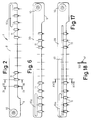
- the saw blade 7 shown in Fig. 2 is the left-hand of the two blades when viewed in the direction of arrow Z in Fig. 1.
- the blade 7 comprises a length 8 of steel strip of constant top-to-bottom dimension over most of its length.
- the top-to-bottom dimension increases over a short length of the strip at the left-hand end thereof (as viewed in Fig. 2) and as indicated at 9.
- An apertured boss 10 is fixed to the strip 8 close to the left-hand end and is used to connect the blade to the drive mechanism referred to above.
- the strip 8 is formed, in a manner described below, to receive cutting teeth 11 at spaced intervals along its length (excluding part 9).
- the tooth pitch is not the same for all teeth, the distance between the fourth and fifth teeth from the left and between the eighth and ninth teeth from the left being slightly greater than the constant distance between the remaining teeth.
- the teeth 11 are of tungsten carbide and are fixed to the strip by first placing them in slots 12 cut in the strip and then brazing the teeth in position in the slots. As can be seen from Fig. 5, the slots extend into the strip from the lower (as viewed in Fig. 5) edge of the latter.
- Each slot 12 has a parallel sided entry portion 13 which leads into a sector-shaped extension 14.
- the entry portion 14 has side edges and a base edge 37 which is generally parallel to the lower edge of the strip 8.
- the entry portion 13 and the extension 14 lie symmetrically with respect to the longitudinal axis A-A of the slot and the extension 14 joins the entry portion 13 centrally of the base edge of the latter as shown.
- the junctions between the base and the extension 14 are gently rounded as indicated at 15.
- the slots extend for a short distance only into the top-to-bottom dimension of the strip 8.
- Alternate teeth along the length of strip 8 are of the configuration shown in Figs. 7-10 while the remainder are of the configuration shown in Figs. 11-14. Starting from the rib of the strip as seen in Fig. 2, odd numbered teeth are as shown in Figs. 7-10, and even numbered teeth are shown in Figs. 11-14.
- the tooth shown in Figs. 7-10 has a pointed portion 16, the side walls of the portion being bevelled in part as indicated at 17.
- the extremity of the portion is downwardly-set (as viewed in Fig. 8) as indicated at 18. The set is sufficient to ensure that the kerf cut is of a width that will permit passage of the support 2.
- the portion 16 merges into a body portion 19 of generally rectangular form when seen in plan as in Fig. 7 with a curved end face 20.
- the body portion 19 has equisized, triangularly-shaped areas 21, 22 over which the depth of the body portion is reduced by about one half to leave a sector-shaped platform 23 disposed centrally of the longitudinal axis B-B of the tooth and whose upper surface lies in a plane that is inclined slightly to that containing the upper surface of portion 16.
- line 24 represents the upper edge of the left-hand end (as viewed in Fig. 9) of the platform 23 and line 25 represents the edge between the upper surfaces of the platform 23 and portion 16.
- the areas 21, 22 are so orientated as to leave shoulders 38 which lie transversely of the axis B.
- each remaining tooth has a pointed portion 27 whose edges are bevelled in part as indicated at 28.
- the extremity of portion 27 is not downwardly set as is the tooth shown in Figs. 7-10 but is straight as shown in Fig. 12. Those teeth ensure the removal of saw dust from the kerf.
- the body portion 29 of the tooth shown in Figs. 11-14 is identical with that of the tooth shown in Figs. 7-10, and has equi-sized, reduced-depth triangularly-shaped areas 30, 31 whose adjacent tips are rounded as at 32.
- the sector-shaped platform 33 that is disposed centrally of the longitudinal axis B-B of the tooth has an upper surface that lies in a plane inclined slightly with respect to that containing the upper surface of portion 27, the inclination being the same as that of the corresponding planes of the tooth shown in Figs. 7-10.
- the inclination can be observed from Fig. 13 where lines 34, 35 correspond with lines 24 and 25 of Fig. 9.
- the body portion 29 also has a curved end face 36, the curvature being identical with that of end face 20.
- the areas 30, 31 are so orientated as to leave shoulders 38 which lie transversely of the axis B-B.
- the teeth are sized so that the platforms 23, 33 will fit into the extensions 14 of the slots in the strip 8.
- the areas 21, 22 thus overlie surface parts of the plate-like strip 8 on each side of the platforms 23, 33.
- the surfaces of the platforms 23, 33 when the tooth is correctly positioned, lie flush with the inner surface of the strips 8 or slightly below that surface.
- the parallel sided entry portions 13 of the slots receive those parts of the teeth between the reduced depth areas and the pointed portions with the base 37 of each entry portion 13 supporting the shoulders 38 of the recessed areas.
- the platforms fit tightly in the vicinity of the rounded parts 15 of the slots but elsewhere there are some small clearances to permit the ready flow of brazing alloy during the brazing of the teeth to the strip 8.
- the other blade 39 is shown in Fig. 6 and is of a configuration generally similar to that of blade 7 but is its mirror image so that the blades can be placed together in side by side contact as indicated in Figs. 3 and 4 with the surfaces of the teeth platforms facing each other.
- the surfaces of the platforms lie flush with or just beneath the respective contacting faces of the saw blades so that side-by-side reciprocating movement of the blade is not impeded and the blades are not separated.
- the teeth 11 of blade 39 are located in positions corresponding with those of teeth 11 on blade 7.
- the teeth 11 are formed by a process in which tungsten carbide particles are first moulded into the required tooth shape and are then sintered for producing a coherent mass of particles.
- the tooth configuration described above faciliates the use of moulding techniques and sintering because there are no severe changes in tooth cross section. Moreover, possible distortion during sintering is minimised because the tooth form has one substantially flat or plane surface on which it can rest during sintering.
- the teeth are located in the position with the platforms engaged in the slots.
- the relatively tight fit between the rounded surfaces 15 and 26 ensures that the teeth are held firmly for subsequent brazing whilst limiting the area of the blade strips over which stressing occurs, because of the tight fit, to a minimum. Subsequently, the teeth are lapped to a required contour.
- the slot concept enables the teeth to be accurately positioned on the strip and in particular ensures that the end faces 20 and 36 of teeth on the same strip lie in line and at a constant predetermined distance from the upper (as seen in Figs. 2 and 6) edge of the strip.
- the end faces thus form bearing edges which slide along the upper edges of the slot in the support 2.
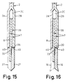
- each saw blade 7, 39 may have a bearing element 41 secured longitudinally to its outer face.
- the bearing element 41 may be a steel strip spot welded or secured in some other way to the saw blade. It may be necessary to reduce slightly the overall length of the teeth and of the slots in which they are located to accommodate the bearing element 41.
- the strips are chrome plated to give a hard surface finish.
- chrome plated is only one is chrome plated.
- circular saw blades may be made with teeth held in slots as may the blades of jig saws and sabre saws, although it will of course be necessary to employ different tooth profiles.
- contour of the slot must provide positive location of the tooth and preferably hold the latter during any subsequent processing for example brazing.
- support surfaces must be provided to support the tooth when exposed to loads.
Landscapes
- Engineering & Computer Science (AREA)
- Mechanical Engineering (AREA)
- Knives (AREA)
- Sawing (AREA)
- Dovetailed Work, And Nailing Machines And Stapling Machines For Wood (AREA)
- Harvester Elements (AREA)
- Treatment Of Fiber Materials (AREA)
Claims (16)
- Lame de scie comprenant un élément porteur (7) comportant au moins un bord et une surface latérale et, réparties le long de ce bord, une série de fentes (12) dans chacune desquelles est fixée une dent de scie (11) s'étendant au-delà dudit bord, et dans laquelle chaque fente (12) est profilée de façon à former un ou des bords de base (37) servant à supporter un ou des bords correspondants (38) de la dent (11) et où une première partie (23) de la dent s'étend au moins partiellement dans la fente (12), caractérisée en ce qu'une autre partie (21, 22 ou 30, 31) de la dent (11) s'étend latéralement au-delà de ladite fente et recouvre une partie de ladite surface latérale.
- Lame de scie telle que revendiquée dans la revendication 1, dans laquelle ladite première partie (23) est plus épaisse que ledit élément porteur (7).
- Lame de scie telle que revendiquée dans la revendication 1 ou 2, dans laquelle ladite autre partie forme un bord d'appui (20, 36).
- Lame de scie telle que revendiquée dans la revendication 1, 2 ou 3, dans laquelle la partie (14) de chacune desdites fentes (12) qui s'adapte à ladite première partie (23) de la dent (11) a dans l'ensemble une forme de secteur.
- Lame de scie telle que revendiquée dans les revendications 3 et 4, dans laquelle la partie incurvée de ladite fente en forme de secteur vient buter contre le bord d'appui (20, 36) prévu sur ladite dent.
- Lame de scie telle que revendiquée dans l'une des revendications précédentes, dans laquelle chaque fente (12) comporte une partie d'entrée (13) pourvue de bords latéraux et dudit bord (37) ou desdits bords de base.
- Lame de scie telle que revendiquée dans les revendications 4 et 6 ou dans les revendications 5 et 6, dans laquelle l'extrémité (15) de la partie en forme de secteur de ladite fente qui est opposée à sa partie incurvée est située au centre du bord de base et ladite partie en forme de secteur est disposée symétriquement par rapport à l'axe longitudinal A-A de la fente (12).
- Lame de scie telle que revendiquée dans la revendication 7, dans laquelle chaque partie (37) dudit bord de base et la paroi latérale adjacente de ladite partie en forme de secteur définissent deux côtés d'une partie, profilée dans l'ensemble en forme de triangle, de ladite surface latérale, les deux parties précitées en forme de triangle étant les parties dudit élément porteur (7) qui sont recouvertes par lesdites autres parties (21, 22 ou 30, 31) de leurs dents respectives.
- Lame de scie telle que revendiquée dans la revendication 8, dans laquelle ladite partie en forme de secteur (14) est en communication avec ladite partie d'entrée (13) par l'intermédiaire d'une ouverture prévue dans ledit bord de base et dont les côtés (15) sont arrondis et sont assemblés de façon serrée avec une partie correspondante d'une dent (11), le reste de la dent étant engagé dans la fente (12) avec un certain jeu.
- Lame de scie telle que revendiquée dans l'une quelconque des revendications précédentes, dans laquelle un bord porteur pour la lame (8) est formé par un élément d'appui (41) fixé sur ladite surface latérale de ladite lame (8) audessus desdites dents (11).
- Lame de scie telle que revendiquée dans la revendication 1, comportant une dent, comprenant une partie de coupe (13) et une partie formant corps (19) profilée pour créer une plateforme (23) centrée par rapport à l'axe longitudinal (B-B) de la dent et destinée à être placée dans ladite fente (12) prévue dans ladite lame de scie (8), ainsi que des épaulements porteurs (21, 22 ou 30, 31) situés transversalement auxdits axes (B-B) et s'étendant au-delà de ladite plate-forme (23), afin de recouvrir ladite partie de ladite surface latérale de ladite lame (8).
- Lame de scie telle que revendiquée dans la revendication 11, dans laquelle ladite plate-forme (23) a une forme de secteur, quand elle est observée en vue en plan, avec son sommet dirigé vers ladite partie de coupe (16).
- Lame de scie telle que revendiquée dans la revendication 12, dans laquelle la partie formant corps (19) comporte une face (23) qui est sensiblement plane.
- Lame de scie telle que revendiquée dans la revendication 13, dans laquelle lesdits épaulements porteurs (21, 22 ou 30, 31) sont sensiblement triangulaires et plus minces que ladite partie formant corps (19).
- Scie motorisée tenue manuellement et comportant deux lames de scies (8) telles que revendiquées dans la revendication 1.
- Scie motorisée tenue manuellement et comprenant des première et seconde lames de scies (8) telles que revendiquées dans la revendication 3 ou dans l'une quelconque des revendications 4 à 10, en dépendance de la revendication 3, scie dans laquelle lesdites lames (8) sont guidées pour un mouvement alternatif longitudinal dans un support (2) et dans laquelle lesdites surfaces d'appui (20, 36) de dents adjacentes coopèrent avec des surfaces latérales (40) dudit support (2) pour supporter lesdites lames (8).
Applications Claiming Priority (2)
| Application Number | Priority Date | Filing Date | Title |
|---|---|---|---|
| GB8822627 | 1988-09-27 | ||
| GB8822627A GB8822627D0 (en) | 1988-09-27 | 1988-09-27 | Improvements in/relating to saws & saw teeth & blades therefor |
Publications (3)
| Publication Number | Publication Date |
|---|---|
| EP0361876A2 EP0361876A2 (fr) | 1990-04-04 |
| EP0361876A3 EP0361876A3 (fr) | 1991-04-03 |
| EP0361876B1 true EP0361876B1 (fr) | 1994-10-19 |
Family
ID=10644287
Family Applications (2)
| Application Number | Title | Priority Date | Filing Date |
|---|---|---|---|
| EP19890309804 Expired - Lifetime EP0361875B1 (fr) | 1988-09-27 | 1989-09-26 | Scies, dents de scie et lames de scie |
| EP19890309805 Expired - Lifetime EP0361876B1 (fr) | 1988-09-27 | 1989-09-26 | Scies, dents de scie et lames de scie |
Family Applications Before (1)
| Application Number | Title | Priority Date | Filing Date |
|---|---|---|---|
| EP19890309804 Expired - Lifetime EP0361875B1 (fr) | 1988-09-27 | 1989-09-26 | Scies, dents de scie et lames de scie |
Country Status (4)
| Country | Link |
|---|---|
| US (1) | US4999915A (fr) |
| EP (2) | EP0361875B1 (fr) |
| DE (2) | DE68918913T2 (fr) |
| GB (1) | GB8822627D0 (fr) |
Families Citing this family (14)
| Publication number | Priority date | Publication date | Assignee | Title |
|---|---|---|---|---|
| GB9103883D0 (en) * | 1991-02-25 | 1991-04-10 | Black & Decker Inc | Saw blades and method of making same |
| DE4140395A1 (de) * | 1991-12-07 | 1993-06-09 | Robert Bosch Gmbh, 7000 Stuttgart, De | Kraftgetriebene saege mit gegensinnig hin- und herbewegbaren saegeblaettern |
| DE4314004B4 (de) * | 1993-04-26 | 2005-12-15 | Black & Decker Inc., Newark | Sägeblatt für eine Säge zum Schneiden von Gas- und/oder Porenbetonsteinen |
| DE29600567U1 (de) * | 1996-01-15 | 1996-09-26 | Wilhelm Putsch oHG, 42855 Remscheid | Sägeblatt für eine oszillierende Maschinensäge |
| GB2315457A (en) * | 1996-07-25 | 1998-02-04 | D J | Cutting apparatus |
| GB0010336D0 (en) | 2000-04-29 | 2000-06-14 | C4 Carbides Plc | Saw blades |
| US6688197B1 (en) * | 2001-09-24 | 2004-02-10 | Leo L. Niemela | Notch sawing apparatus for dove-tail joints |
| EP1855837A4 (fr) * | 2005-01-27 | 2009-04-08 | Jon S Ritter | Outil en carbure de tungstene |
| WO2010148471A1 (fr) * | 2009-06-23 | 2010-12-29 | Scies B.G.R. Inc. | Extrémité de dent de scie |
| DE102012210164A1 (de) * | 2012-06-18 | 2013-12-19 | Robert Bosch Gmbh | Verfahren zum Herstellen eines Sägeblatts |
| US9101992B2 (en) * | 2013-11-18 | 2015-08-11 | Ningbo Gemay Industry Co., Inc | Reciprocating saw blade assembly |
| US9498832B2 (en) * | 2013-11-18 | 2016-11-22 | Richpower Industries Inc. | Reciprocating saw blade assembly |
| GB2578516A (en) * | 2019-09-08 | 2020-05-13 | Spencer Ford Duncan | Saw Blade |
| CN117601198A (zh) * | 2024-01-10 | 2024-02-27 | 浙江武义好宇百联工贸有限公司 | 一种往复锯片结构 |
Family Cites Families (7)
| Publication number | Priority date | Publication date | Assignee | Title |
|---|---|---|---|---|
| US1711016A (en) * | 1927-06-04 | 1929-04-30 | Dubois Lionel | Stone-sawing machine |
| US2344262A (en) * | 1943-11-10 | 1944-03-14 | Odierna Ernest | Surgical cast cutter |
| DE8301931U1 (de) * | 1983-01-25 | 1983-07-14 | Frank, Helmut, 5630 Remscheid, De | Motorsaege |
| DE3307170C2 (de) * | 1983-03-01 | 1986-08-14 | Wilhelm H. Kullmann WIKUS-Sägenfabrik, 3509 Spangenberg | Sägeblatt und Verfahren zu seiner Herstellung |
| US4690024A (en) * | 1985-02-28 | 1987-09-01 | Black & Decker Inc. | Saw blade and tip therefor |
| SE463501B (sv) * | 1986-10-06 | 1990-12-03 | Sandvik Ab | Anordning vid motordriven saag |
| EP0267311A1 (fr) * | 1986-11-11 | 1988-05-18 | Black & Decker Inc. | Lame de scie pour une scie avec deux lames disposées côte à côte en parallèle et oscillantes en sens inverse |
-
1988
- 1988-09-27 GB GB8822627A patent/GB8822627D0/en active Pending
-
1989
- 1989-09-25 US US07/412,762 patent/US4999915A/en not_active Expired - Lifetime
- 1989-09-26 EP EP19890309804 patent/EP0361875B1/fr not_active Expired - Lifetime
- 1989-09-26 DE DE68918913T patent/DE68918913T2/de not_active Expired - Lifetime
- 1989-09-26 DE DE68921398T patent/DE68921398T2/de not_active Expired - Lifetime
- 1989-09-26 EP EP19890309805 patent/EP0361876B1/fr not_active Expired - Lifetime
Also Published As
| Publication number | Publication date |
|---|---|
| DE68918913D1 (de) | 1994-11-24 |
| GB8822627D0 (en) | 1988-11-02 |
| EP0361875B1 (fr) | 1995-03-01 |
| EP0361876A2 (fr) | 1990-04-04 |
| DE68921398D1 (de) | 1995-04-06 |
| DE68918913T2 (de) | 1995-02-23 |
| EP0361875A3 (fr) | 1991-04-03 |
| EP0361876A3 (fr) | 1991-04-03 |
| US4999915A (en) | 1991-03-19 |
| DE68921398T2 (de) | 1995-06-29 |
| EP0361875A2 (fr) | 1990-04-04 |
Similar Documents
| Publication | Publication Date | Title |
|---|---|---|
| EP0361875B1 (fr) | Scies, dents de scie et lames de scie | |
| US4784034A (en) | Saw blades and saw assemblies | |
| JP4503921B2 (ja) | 鋸刃 | |
| US20020121023A1 (en) | Saw blade for hand-held tools | |
| US4690024A (en) | Saw blade and tip therefor | |
| US5884547A (en) | Saw blade tooth form | |
| EP3162484B1 (fr) | Lame de scie alternative | |
| US4738594A (en) | Blades for axial fans | |
| CA2228087A1 (fr) | Lame de scie | |
| US4324163A (en) | Circular saw construction | |
| US4893411A (en) | Power sawblades for abrasive materials | |
| KR910004876Y1 (ko) | 용접건용 팁 드레서(Tip Dresser)의 커터(Cutter) | |
| JPS6239113A (ja) | 丸鋸及びその製造方法 | |
| EP0334594A2 (fr) | Outils à dents rapportées | |
| US3990334A (en) | Method and saw blade for the sawing of particularly wood | |
| JPH07314205A (ja) | 溝切用バイト | |
| GB2100187A (en) | Wood working saws | |
| CN1293102A (zh) | 线锯,尤其是精切锯 | |
| GB2052374A (en) | Reinforcing tip for a sawtooth | |
| JPH0215603Y2 (fr) | ||
| EP0622165A1 (fr) | Dent de scie | |
| SU990443A1 (ru) | Инструмент дл сн ти фасок по профил м зубьев зубчатых колес | |
| JPH04176490A (ja) | 電気カミソリ | |
| JP2000052140A (ja) | 円形カッター | |
| CN209175018U (zh) | 切割部件 |
Legal Events
| Date | Code | Title | Description |
|---|---|---|---|
| PUAI | Public reference made under article 153(3) epc to a published international application that has entered the european phase |
Free format text: ORIGINAL CODE: 0009012 |
|
| AK | Designated contracting states |
Kind code of ref document: A2 Designated state(s): CH DE FR GB IT LI SE |
|
| PUAL | Search report despatched |
Free format text: ORIGINAL CODE: 0009013 |
|
| AK | Designated contracting states |
Kind code of ref document: A3 Designated state(s): CH DE FR GB IT LI SE |
|
| RHK1 | Main classification (correction) |
Ipc: B23D 49/00 |
|
| 17P | Request for examination filed |
Effective date: 19910911 |
|
| 17Q | First examination report despatched |
Effective date: 19921008 |
|
| GRAA | (expected) grant |
Free format text: ORIGINAL CODE: 0009210 |
|
| AK | Designated contracting states |
Kind code of ref document: B1 Designated state(s): CH DE FR GB IT LI SE |
|
| REF | Corresponds to: |
Ref document number: 68918913 Country of ref document: DE Date of ref document: 19941124 |
|
| ET | Fr: translation filed | ||
| ITF | It: translation for a ep patent filed | ||
| EAL | Se: european patent in force in sweden |
Ref document number: 89309805.3 |
|
| PLBE | No opposition filed within time limit |
Free format text: ORIGINAL CODE: 0009261 |
|
| STAA | Information on the status of an ep patent application or granted ep patent |
Free format text: STATUS: NO OPPOSITION FILED WITHIN TIME LIMIT |
|
| 26N | No opposition filed | ||
| REG | Reference to a national code |
Ref country code: GB Ref legal event code: IF02 |
|
| PGFP | Annual fee paid to national office [announced via postgrant information from national office to epo] |
Ref country code: CH Payment date: 20080930 Year of fee payment: 20 |
|
| PGFP | Annual fee paid to national office [announced via postgrant information from national office to epo] |
Ref country code: FR Payment date: 20080917 Year of fee payment: 20 |
|
| PGFP | Annual fee paid to national office [announced via postgrant information from national office to epo] |
Ref country code: GB Payment date: 20080929 Year of fee payment: 20 |
|
| PGFP | Annual fee paid to national office [announced via postgrant information from national office to epo] |
Ref country code: DE Payment date: 20081031 Year of fee payment: 20 |
|
| PGFP | Annual fee paid to national office [announced via postgrant information from national office to epo] |
Ref country code: IT Payment date: 20080929 Year of fee payment: 20 Ref country code: SE Payment date: 20080929 Year of fee payment: 20 |
|
| REG | Reference to a national code |
Ref country code: CH Ref legal event code: PL |
|
| REG | Reference to a national code |
Ref country code: GB Ref legal event code: PE20 Expiry date: 20090925 |
|
| EUG | Se: european patent has lapsed | ||
| PG25 | Lapsed in a contracting state [announced via postgrant information from national office to epo] |
Ref country code: GB Free format text: LAPSE BECAUSE OF EXPIRATION OF PROTECTION Effective date: 20090925 |