EP0362215B1 - Entrainement ameliore pour joint d'etancheite du type rondelle a bande - Google Patents
Entrainement ameliore pour joint d'etancheite du type rondelle a bande Download PDFInfo
- Publication number
- EP0362215B1 EP0362215B1 EP88903475A EP88903475A EP0362215B1 EP 0362215 B1 EP0362215 B1 EP 0362215B1 EP 88903475 A EP88903475 A EP 88903475A EP 88903475 A EP88903475 A EP 88903475A EP 0362215 B1 EP0362215 B1 EP 0362215B1
- Authority
- EP
- European Patent Office
- Prior art keywords
- washer
- sleeve
- flange
- band
- mechanical seal
- Prior art date
- Legal status (The legal status is an assumption and is not a legal conclusion. Google has not performed a legal analysis and makes no representation as to the accuracy of the status listed.)
- Expired - Lifetime
Links
- 239000000919 ceramic Substances 0.000 claims abstract description 21
- 238000007789 sealing Methods 0.000 claims abstract description 17
- 230000002093 peripheral effect Effects 0.000 claims 1
- 239000002184 metal Substances 0.000 description 17
- 230000035939 shock Effects 0.000 description 6
- 230000006835 compression Effects 0.000 description 3
- 238000007906 compression Methods 0.000 description 3
- 239000002826 coolant Substances 0.000 description 3
- 239000012530 fluid Substances 0.000 description 3
- 238000009987 spinning Methods 0.000 description 3
- 238000002485 combustion reaction Methods 0.000 description 2
- 238000001816 cooling Methods 0.000 description 2
- 230000003068 static effect Effects 0.000 description 2
- 238000007792 addition Methods 0.000 description 1
- 229910010293 ceramic material Inorganic materials 0.000 description 1
- 230000000694 effects Effects 0.000 description 1
- 229920001971 elastomer Polymers 0.000 description 1
- 239000000806 elastomer Substances 0.000 description 1
- 238000009434 installation Methods 0.000 description 1
- 239000007788 liquid Substances 0.000 description 1
- 239000000463 material Substances 0.000 description 1
- 230000013011 mating Effects 0.000 description 1
- 230000004048 modification Effects 0.000 description 1
- 238000012986 modification Methods 0.000 description 1
Images

Classifications
-
- F—MECHANICAL ENGINEERING; LIGHTING; HEATING; WEAPONS; BLASTING
- F16—ENGINEERING ELEMENTS AND UNITS; GENERAL MEASURES FOR PRODUCING AND MAINTAINING EFFECTIVE FUNCTIONING OF MACHINES OR INSTALLATIONS; THERMAL INSULATION IN GENERAL
- F16J—PISTONS; CYLINDERS; SEALINGS
- F16J15/00—Sealings
- F16J15/16—Sealings between relatively-moving surfaces
- F16J15/34—Sealings between relatively-moving surfaces with slip-ring pressed against a more or less radial face on one member
- F16J15/36—Sealings between relatively-moving surfaces with slip-ring pressed against a more or less radial face on one member connected by a diaphragm or bellow to the other member
-
- F—MECHANICAL ENGINEERING; LIGHTING; HEATING; WEAPONS; BLASTING
- F16—ENGINEERING ELEMENTS AND UNITS; GENERAL MEASURES FOR PRODUCING AND MAINTAINING EFFECTIVE FUNCTIONING OF MACHINES OR INSTALLATIONS; THERMAL INSULATION IN GENERAL
- F16J—PISTONS; CYLINDERS; SEALINGS
- F16J15/00—Sealings
- F16J15/16—Sealings between relatively-moving surfaces
- F16J15/34—Sealings between relatively-moving surfaces with slip-ring pressed against a more or less radial face on one member
- F16J15/3464—Mounting of the seal
- F16J15/348—Pre-assembled seals, e.g. cartridge seals
Definitions
- the present invention relates to rotary mechanical seals used to prevent leakage of fluids along a shaft rotatable in a housing.
- Such seals utilize a pair of contacting washers: one annular washer or ring is sealed with respect to the shaft and rotates with the shaft; the other is sealed with respect to a housing and is stationary.
- the device of the present invention provides an improved drive to the rotatable washer to insure that the washer rotates with the rotation of the shaft.
- Rotary mechanical seals are known and are particularly useful in a variety of applications, for example, in coolant pumps in the cooling systems of internal combustion engines.
- one of the sealing washers is typically made of a hard, rigid material such as ceramic.
- the coolant may be subject to sudden and extreme temperature changes which subject the ceramic washer to thermal shock; the washer may expand unevenly, causing it to crack and the seal to fail.
- United States Patent No. 3,782,735 discloses the use of a metal band around the ceramic washer.
- the metal band has an interference fit with the ceramic washer at one end.
- the band defines a radially directed annular fin. Because of the interference fit between the ceramic washer and the metal band, the ceramic washer is in a constant state of compression, thereby increasing the washer's resistance to thermal shock.
- the annular fin aids in dissipating heat from the ceramic washer into the fluid being pumped.
- the ceramic washer is carried by a sleeve pressed onto the shaft.
- An elastomeric washer is disposed between the sleeve and the washer to provide a static seal and also to provide a means for driving the washer.
- the rotary mechanical seal disclosed in Novosad Patent No. 3,782,735 protects the ceramic washer from thermal shock, ceramic washers driven solely by this frictional connection between the washer and sleeve may, in some instances, spin relative to the pump shaft.
- the present invention provides a rotary mechanical seal which uses an improved drive to rotate the ceramic washer.
- the seals of the present invention are particularly useful as seals in coolant pumps in the cooling systems of internal combustion engines.
- the driven ring is arranged with means to both protect the seal from damage due to the thermal shock and to insure that the rotating seal element rotates with the shaft.
- the present invention provides a rotary mechanical seal of the type disclosed in United States Patent No. 3,782,735. It includes a banded ceramic washer which rotates with the shaft and co-operates with a second washer which is stationary to establish relatively rotating contacting seal faces.
- the ceramic washer is banded in accordance with the principles of the aforesaid patent.
- a sleeve is press-fit coaxially onto a shaft and adapted to rotate with the shaft.
- a cylindrical body portion coaxial with the shaft, receives the banded washer.
- a flange extends radially from the body, and defines means to engage the metal band of a banded sealing washer adjacent the outer periperal diameter of the band.
- the band includes cooperating means which is engaged by the means on the sleeve.
- Figure 1 is an axial section, through one embodiment of an illustrated rotary mechanical seal made in accordance with the principles of the present invention.
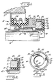
- Figure 2 is a partial axial section, of a second embodiment of an illustrative rotary mechanical seal.
- Figure 3 is an end view of the rotary mechanical seal as viewed from the right side of Figure 2.
- Figure 4 is a view similar to Figure 2, showing a further alternate embodiment of a rotary mechanical seal.
- Figure 5 is an end view of the rotary mechanical seal as viewed from the right side of Figure 4.
- Figure 6 is an end view of a further alternate embodiment, looking in the direction opposite to the view of Figure 5.
- Figure 7 is a partially exploded perspective view of the seal of Figure 6.
- the seal generally designated 10 is intended to provide a liquid tight seal between housing 11 and shaft 12, of a pump or other device. It is mounted coaxially, on shaft 12.
- the seal 10 uses two relatively rotating contacting washers 14, 16 which define running seal surfaces, defining stationary and rotating sealing surfaces.
- One washer 14 is mounted for non-rotative but limited axial movement; the other washer 16 is rotatable, with the pump shaft 12 and is in fixed axial position. The parts could however, be reversed, with the axially movable washer connected to the rotatable shaft.
- the non-rotating washer 14 is mounted in a metal retainer 18, which is press-fit into a bore of the pump housing 11.
- the retainer 18 is sealed with respect to the pump housing by the press-fit of the retainer in the housing.
- the washer 14 defines a flat, smooth, radially disposed sealing surface 20 on one side.
- the opposite side of the washer 14 bears against a flexible resilient bellows member 22 extending between the ring or washer 14 and the metal retainer 18.
- a spring 24 is interposed between the two ends of the bellows member 22, and effects a fluid-tight seal between the retainer 18 and the washer 14.
- the spring 24 also biases the sealing surface 20 of the first washer 14 against the rotatable washer 16.
- Ring 14 includes a series of grooves 15 at its inside diameter defined by partially cylindrical surfaces.
- Sleeve 18 includes mating detents 19 which extend into grooves 15 and fix ring 14 against rotation but permit axial movement along the shaft 12.
- the sealing surface 20 of the non-rotating washer 14 bears against a similar flat, smooth, radially disposed sealing surface 26 of the rotatable washer 16.
- the rotatable washer 16 is preferably made of a ceramic material. To obviate thermal shock problems, the perimeter of the rotatable washer 16 is circumscribed by a metal band 28 as described in United States Patent No. 3,782,735.
- the metal band 28 is annular and one end 30 is of a larger diameter than opposite end 32 and tapers to provide an interference fit around the washer 16 at end 32.
- the oversized end is flared outwardly to form a short radial fin or flange 34.
- the fin 34 defines an axial edge surface 36 at its perimeter or outer periphery.
- Sleeve 40 includes a cylindrical body 42 frictionally mounted coaxially on the pump shaft 12 for rotation with the shaft.
- the interference between the sleeve 40 and the shaft 12 should be a minimum of 2,54 ⁇ 10 ⁇ 5 m (0.001 inch).
- the body is enlarged away from the shaft 12.
- the flared end 44 engages the metal retainer 18 when the seal is not installed in a pump wall to form a unitary seal package.
- the retainer engages the housing and is fixed in an axial position, further axial movement of sleeve 40 moves flared end 44 away from the retainer causing compression of spring 24. In this manner a predetermined load may be placed on the seal faces during installation.
- sleeve 40 At its opposite end sleeve 40 includes a radial flange 46 extending radially from the sleeve body. Flange 46 is provided with an integral, annular, axially-directed wall 48 extending axially toward the non-rotating washer 14 concentric with and overlying body 44.
- a flanged flexible resilient ring 38 is interposed between the banded rotatable washer 16 and sleeve 40 to seal against fluid leakage. It is made of an elastomer and includes radial portion 39 and axial portion 41. The sleeve body 42, flange 46, and axial annular wall encircle the banded washer 16. The resilient ring 38 provides a static seal therebetween.
- the resilient ring 38 and banded washer 16 are sized such that the ring 38 is compressed into the space defined by the sleeve body 42, flange 46, and upon the inner surface of sleeve 40 and wall 48. As shown in the drawing, the resilient ring or washer 38 bears against the inner surfaces of the sleeve 42 body and flange 46. This arrangement provides a frictional drive path between the sleeve 42 and ring 16.
- the fin or flange 36 of the metal band 28 and the inner diameter of axial wall 48 are sized such that surface 36 contacts the inner surface of the axial wall 48, and is frictionally engaged therewith.
- This frictional engagement of the metal band 28 and sleeve wall 48 provides sufficient drive torque to insure rotation of the rotatable washer 16 and prevent spinning relative to the sleeve 40 and shaft 12.
- a minimum of 2,54 ⁇ 10 ⁇ 5 m (0.001 inch) interference is provided between the outer diameter of the surface 36 and the inner diameter of axial wall 48 to insure frictional drive.
- the banded washer 16 is held between the sleeve wall 48 and the resilient ring 38. Because of the compression of the ring 38, washer 16 will be driven by sleeve 40 through ring 38 and also through frictional engagement of axially directed wall 48 with axial edge surface 36 of flange 34. The drive torque thus provided is greater than that provided by the resilient ring 38, alone.
- the contacting surfaces of the extension and band fin provide a means for driving the rotatable washer, and thereby, the present invention serves to prevent the washer from spinning relative to the sleeve 40 or pump shaft 12.
- the metal band 28 includes radial flange 34 and axial edge surface 36.
- flange 34 also includes a plurality of slots or notches 80 disposed on the outer circumference of the flange 34 of band 28. The slots define pairs of generally parallel driven surfaces 81.
- the integral flange 46 of sleeve 40 is radially directed as in the prior embodiment.
- it instead of a radial wall concentric with sleeve 40, it includes a plurality of axial drive lugs 82 which extend toward the opposite end 44 of the sleeve. Each defines a pair of generally radial drive surfaces 83 disposed between driven surfaces 81.
- the illustrated embodiment discloses a metal band 28 including four slots or notches 80 disposed 90° apart.
- the flange 46 of sleeve 40 has only one pair of diametrically opposed lugs 82. Any desired number of slots and lugs may be used, so long as a positive connection between the band 28 and sleeve 40 is achieved.
- FIGS 4 and 5 illustrate a further alternate arrangement for providing a positive drive between a sleeve and rotatable washer.
- This form of the sleeve 50 includes a body 52 adapted to be press fit on the end of a shaft as in the previous embodiments.
- the outer end of the sleeve 50 has a radial flange 54 which extends to an integral, annular, axially-directed wall 56 spaced from sleeve body 52.
- An outwardly flaring lip 58 is formed along the inside edge of the wall 56.
- Three detents or crimps 60 are formed in the wall 56 and extend radially inwardly therefrom. In the illustrated embodiment the detents are formed as a semi-cylindrical surface, any number of alternate shapes, however, could be used.
- a resilient ring 62 having a foreshortened radial portion mounts the ceramic rotatable washer 64.
- the washer has an annular groove 66 for receiving the radial portion of resilient ring 62. The portion of the washer 64 beyond the grove 66 engages the inner surface of the flange 54.
- a metal band 68 similar to the band 28 extends around the periphery of the washer 64.
- Band 68 has a radial fin or flange 70 at its edge underneath the wall 56.
- Arcuate grooves or cutouts 72 are formed at spaced locations around the flange 70.
- the detents 60 mate or cooperate with the grooves 72, as best seen in Figure 5, to positively engage the sleeve 50 and metal band 68 for rotation. This provides a drive for the band, and thus the washer 64, for rotation of the washer with the shaft.
- Figures 6 and 7 illustrate yet another alternate means for positively driving the rotatable washer.
- the sleeve 50 is essentially the same as that in Figures 4 and 5 with the exception that detents 60 are replaced by two sets of tabs 90 and 92.
- Each set has two tabs formed 180 o apart in the axially-directed wall 56. The tabs extend inwardly from the annulus of the wall 56.
- the tabs of one set, 92 are directed toward a clockwise direction.
- the tabs 90 of the other set are directed in a counterclockwise direction.
- the drive therefore is suitable for either direction of rotation of the shaft.
- the fin 34 has a series of axial grooves or notches 96 on its outer surface. Tabs 90 and 92 engage the notches 96 to provide a positive drive between the sleeve and washer.
- tabs 90 and 92 engage the notches 96 to provide a positive drive between the sleeve and washer.
Landscapes
- Engineering & Computer Science (AREA)
- General Engineering & Computer Science (AREA)
- Mechanical Engineering (AREA)
- Mechanical Sealing (AREA)
- Sealing Devices (AREA)
- Glass Compositions (AREA)
- Centrifugal Separators (AREA)
- Reciprocating, Oscillating Or Vibrating Motors (AREA)
- Lubrication Of Internal Combustion Engines (AREA)
- Lubrication Details And Ventilation Of Internal Combustion Engines (AREA)
- Bolts, Nuts, And Washers (AREA)
Claims (22)
- Joint mécanique rotatif comprenant un manchon rigide (40 ; 50) destiné à être monté sur un arbre rotatif (12) pour tourner avec lui, une rondelle d'étanchéité annulaire (16, 64) définissant une face d'étanchéité radiale (26), et montée sur ledit manchon (40, 50) pour tourner avec lui, une frette annulaire séparée (28; 68; 94) circonscrivant ladite rondelle (16, 64) en engagement à frottement serré avec elle, ladite frette (28, 68, 94) comportant une joue généralement radiale (34, 70), ledit manchon (40, 50) étant disposé en contact d'engagement avec ladite joue radiale (34, 70) de ladite frette (28, 68, 94).
- Joint mécanique rotatif selon la revendication 1, dans lequel ladite rondelle d'étanchéité (16, 64) est fabriquée en céramique.
- Joint mécanique rotatif selon la revendication 1, dans lequel ledit manchon (40) comprend un corps annulaire (42), adapté de façon à s'engager en frottement avec l'arbre rotatif (12), ledit manchon (40) comprenant en outre une joue radiale (46), ladite joue (46) comprenant une paroi axiale annulaire (48) concentrique avec ledit corps (42) et l'entourant, ladite rondelle (16) étant disposée entre ledit corps (42) et ladite paroi axiale annulaire (48), ladite joue généralement radiale (34) de ladite frette (28) comportant un rebord axial (36), ledit rebord (36) venant engager en frottement contre ladite paroi axiale (48) dudit manchon (40).
- Joint mécanique rotatif selon la revendication 2, dans lequel ledit manchon (40) comprend un corps annulaire (42) adapté de façon à s'engager en frottement avec ledit arbre rotatif (12), ledit manchon (40) comprenant en outre une joue radiale (46), ladite joue (46) comprenant au moins une patte (82) dirigée axialement, ladite rondelle (16) étant disposée entre ledit corps (42) et ladite patte (82) dirigée axialement, ladite joue généralement radiale (34) de ladite frette (28) comportant au moins une encoche (80) qui y est formée, ladite patte (82) définissant au moins une surface d'entraînement (83), ladite encoche (80) définissant au moins une surface entrainée (81), ladite patte (82) étant disposée dans ladite ouverture avec ladite surface (83) d'entraînement disposée pour s'engager avec ladite surface entraînée (81) de façon à assurer un engagement d'entraînement positif entre ladite frette (28) et ledit manchon (40).
- Joint mécanique rotatif selon la revendication 4, dans lequel ledit manchon (40) comprend une pluralité de pattes (82) et la frette (28) comprend une pluralité d'encoches (80), chacune desdites pattes (82) définissant au moins une surface d'entraînement (83) et chacune desdites encoches (80) définissant au moins une surface entraînée (81) disposée dans une desdites encoches (80) avec la surface d'entraînement (83) disposée pour assurer l'engagement en entraînement de ladite surface entraînée (81) de façon à assurer l'engagement en entraînement entre ledit manchon (40) et ladite frette (28).
- Joint mécanique rotatif selon la revendication 5, dans lequel lesdites pattes (82) et lesdites ouvertures sont espacées circonférentiellement de façon égale.
- Joint mécanique rotatif selon la revendication 4, dans lequel ladite joue (34) de ladite frette (28) comprend au moins une encoche périphérique découpée (80) définissant ladite surface entraînée (81), ladite surface d'entraînement (83) sur ladite patte (82) et ladite surface entraînée (81) sur ladite frette (28) étant dirigées de façon générale radialement en recevant une patte (82) dudit manchon (40).
- Joint mécanique rotatif selon la revendication 3, dans lequel une bague élastique (38) est disposée entre ladite rondelle (16) et ledit corps (42), ledit corps (42) et ladite rondelle (16) étant dimensionnés de telle façon que ladite rondelle (16) est comprimée entre les deux et est en engagement d'étanchéité avec ledit corps (42) et avec ladite rondelle (16).
- Joint mécanique rotatif selon la revendication 5, dans lequel une bague élastique (38) est disposée entre ladite rondelle (16) et ledit corps (42), ledit corps (42) et ladite rondelle (16) étant dimensionnés de telle façon que ladite rondelle (16) est comprimée entre eux et se trouve en engagement d'étanchéité avec ledit corps (42) et avec ladite rondelle (16).
- Joint mécanique rotatif selon la revendication 6, dans lequel lesdites encoches (80) et lesdites pattes (82) sont disposées par paires, diamétralement opposées.
- Joint mécanique rotatif selon la revendication 10, dans lequel ladite frette (28) comprend deux paires d'encoches (80) et ladite joue (46) comprend une paire desdites pattes (82).
- Joint mécanique rotatif selon la revendication 1, dans lequel le manchon (50) présente un corps annulaire (52) s'engageant avec l'arbre rotatif (12) et une joue radiale (54) reliée au corps (52), la joue (54) comprenant en outre une paroi annulaire axiale (56) qui comporte au moins un chien d'arrêt s'étendant radialement (60) dans cette paroi, la paroi axiale (56) étant concentrique audit corps (52) et l'entourant et étant écartée dudit corps avec ladite rondelle (64) disposée entre le corps (52) et la paroi axiale (56), et ladite joue radiale (70) de ladite frette annulaire (68) comportant au moins une gorge (72) qui y est formée, coopérant avec le chien d'arrêt (60) de façon à assurer un engagement d'entraînement positif entre le manchon (50) et la frette (68).
- Joint mécanique rotatif selon la revendication 12, dans lequel ladite paroi annulaire axiale (56) de ladite joue (54) dudit manchon (50) comprend trois chiens d'arrêt (60) s'étendant radialement, également espacés, et ladite joue (70) de ladite frette annulaire (68) comprend trois gorges (72), chacune coopérant avec l'un desdits chiens d'arrêt (60).
- Joint mécanique rotatif selon la revendication 12, dans lequel ledit chien d'arrêt (60) est constitué comme une surface semi-cylindrique et ladite au moins une gorge (72) formée dans ladite joue (70) de ladite frette (68) est conformée en étant recourbée de façon à épouser la surface dudit au moins un chien d'arrêt (60).
- Joint mécanique rotatif selon la revendication 13, dans lequel chacun desdits chiens d'arrêt (60) est formé comme une surface semi-cylindrique et chacune desdites gorges (72) formée dans ladite joue (70) de ladite frette (68) est conformée en étant recourbée de façon à épouser la surface desdits chiens d'arrêts (60).
- Joint mécanique rotatif selon la revendication 1, dans lequel ledit manchon (50) comprend un corps annulaire (52) adapté de façon à venir en contact de frottement contre ledit arbre rotatif (12) et une joue radiale (54) reliée audit corps (52), ladite joue (54) comprenant en outre une paroi axiale annulaire (56) qui comporte au moins une languette s'étendant vers l'intérieur (90, 92) et qui y est formée, ladite joue (54) de ladite paroi axiale (56) étant concentrique audit corps (52) et l'entourant et en étant espacée avec la rondelle (64) qui est disposée entre le corps (52) et la paroi axiale (56), ladite frette annulaire (94) comprenant au moins une encoche (96) qui y est formée dans laquelle s'engage ladite languette (90, 92) pour assurer l'engagement en entraînement positif entre le manchon (50) et ladite frette (94).
- Joint mécanique rotatif selon la revendication 16, dans lequel ladite paroi annulaire axiale (56) de ladite joue (54) dudit manchon (50) comprend deux languettes espacées les unes des autres et dirigées en opposition, et ladite joue (70) de ladite frette annulaire (94) comprend au moins deux encoches (96) dans chacune desquelles s'engage l'une desdites languettes (90, 92).
- Joint mécanique rotatif selon la revendication 17, dans lequel ladite paroi annulaire axiale (56) de ladite joue (54) dudit manchon (50) comprend deux paires de languettes espacées (90, 92), les languettes (90, 92) de chaque paire étant dirigées en sens opposé et dans lequel ladite joue (70) de ladite frette annulaire (94) comprend au moins quatre encoches (96) dans chacune desquelles est engagée l'une desdites languettes (90, 92).
- Joint mécanique rotatif selon la revendication 18, dans lequel lesdites languettes (90, 92) de chaque paire sont espacées d'environ 180°.
- Joint mécanique rotatif selon la revendication 3, dans lequel ladite rondelle d'étanchéité (16) est fabriquée en céramique.
- Joint mécanique rotatif selon la revendication 12, dans lequel ladite rondelle d'étanchéité (64) est fabriquée en céramique.
- Joint mécanique rotatif selon la revendication 16, dans lequel ladite rondelle d'étanchéité (64) est fabriquée en céramique.
Applications Claiming Priority (3)
| Application Number | Priority Date | Filing Date | Title |
|---|---|---|---|
| US07/048,072 US4779876A (en) | 1987-05-11 | 1987-05-11 | Drive for banded washer type seal |
| US48072 | 1987-05-11 | ||
| PCT/US1988/000306 WO1988008935A1 (fr) | 1987-05-11 | 1988-02-03 | Entrainement ameliore pour joint d'etancheite du type rondelle a bande |
Publications (3)
| Publication Number | Publication Date |
|---|---|
| EP0362215A1 EP0362215A1 (fr) | 1990-04-11 |
| EP0362215A4 EP0362215A4 (en) | 1992-05-13 |
| EP0362215B1 true EP0362215B1 (fr) | 1994-06-08 |
Family
ID=21952593
Family Applications (1)
| Application Number | Title | Priority Date | Filing Date |
|---|---|---|---|
| EP88903475A Expired - Lifetime EP0362215B1 (fr) | 1987-05-11 | 1988-02-03 | Entrainement ameliore pour joint d'etancheite du type rondelle a bande |
Country Status (10)
| Country | Link |
|---|---|
| US (1) | US4779876A (fr) |
| EP (1) | EP0362215B1 (fr) |
| JP (1) | JPH02503706A (fr) |
| KR (1) | KR890701937A (fr) |
| AT (1) | ATE107000T1 (fr) |
| AU (1) | AU626257B2 (fr) |
| BR (1) | BR8807500A (fr) |
| CA (1) | CA1312886C (fr) |
| DE (1) | DE3850108T2 (fr) |
| WO (1) | WO1988008935A1 (fr) |
Families Citing this family (45)
| Publication number | Priority date | Publication date | Assignee | Title |
|---|---|---|---|---|
| DE3821352C1 (fr) * | 1988-06-24 | 1989-11-02 | Goetze Ag, 5093 Burscheid, De | |
| CH676811A5 (fr) * | 1988-09-29 | 1991-03-15 | Stopinc Ag | |
| US4969652A (en) * | 1989-04-03 | 1990-11-13 | General Motors Corporation | Cooled shaft seal |
| DE3927589C2 (de) * | 1989-08-22 | 1994-09-29 | Kaco Gmbh Co | Dichtungseinheit |
| DE3929618A1 (de) * | 1989-09-06 | 1991-03-07 | Burgmann Dichtungswerk Feodor | Ringanordnung fuer eine gleitringdichtung |
| US5045048A (en) * | 1990-03-29 | 1991-09-03 | Haemonetics Corporation | Rotary centrifuge bowl and seal for blood processing |
| US5123660A (en) * | 1990-09-20 | 1992-06-23 | Freudenberg-Nok General Partnership | Extended life mechanical face seal assembly |
| JPH0487067U (fr) * | 1990-12-11 | 1992-07-29 | ||
| JPH0487069U (fr) * | 1990-12-12 | 1992-07-29 | ||
| JP2545725Y2 (ja) * | 1990-12-12 | 1997-08-27 | イーグル工業株式会社 | メカニカルシール |
| US5192085A (en) * | 1990-12-17 | 1993-03-09 | Mconie Robert | Rubber drive system mechanical seal |
| JPH0495366U (fr) * | 1991-01-16 | 1992-08-18 | ||
| US5141416A (en) * | 1991-02-14 | 1992-08-25 | Dover Resources, Inc. | Plunger for a downhole reciprocating oil well pump and the method of manufacture thereof |
| GB2254116B (en) * | 1991-03-29 | 1995-01-18 | Rexnord Corp | Shaft seal assemblies |
| AU676466B2 (en) * | 1993-03-09 | 1997-03-13 | Robert Mconie | Flexible drive split mechanical seal |
| US5947479A (en) * | 1995-03-31 | 1999-09-07 | John Crane Inc. | Mechanical seal with flexible metal diaphragm |
| DE69629366D1 (de) * | 1995-03-31 | 2003-09-11 | Crane John Inc | Gleitringdichtung mit flexibler metallmembran |
| US5676382A (en) * | 1995-06-06 | 1997-10-14 | Freudenberg Nok General Partnership | Mechanical face seal assembly including a gasket |
| US6314808B1 (en) * | 1996-02-27 | 2001-11-13 | Felsted Products Llc | Fluid level measuring device |
| US6068263A (en) * | 1997-12-17 | 2000-05-30 | A.W. Chesterton Company | Split mechanical face seal with resilient pivoting member |
| JP2000074226A (ja) * | 1998-08-27 | 2000-03-14 | Eagle Ind Co Ltd | メカニカルシール |
| DE19846153C1 (de) | 1998-10-07 | 2000-04-20 | Freudenberg Carl Fa | Gleitringdichtung |
| DE19914930A1 (de) * | 1999-04-01 | 2000-10-19 | Freudenberg Carl Fa | Gleitringdichtung |
| DE19914929C2 (de) * | 1999-04-01 | 2001-07-19 | Freudenberg Carl Fa | Gleitringdichtung |
| US7581734B1 (en) * | 2000-05-01 | 2009-09-01 | Schlumberger Technology Corporation | Peek coated seal surfaces |
| US6398223B1 (en) | 2000-08-21 | 2002-06-04 | John Crane Inc. | Mechanical face seal |
| US6805357B2 (en) * | 2001-05-18 | 2004-10-19 | Freudenberg-Nok Gp | Bellows face seal assembly |
| US6935044B2 (en) * | 2001-06-13 | 2005-08-30 | Orscheln Products Llc | Connection system for a fluid level measuring device |
| US6988403B2 (en) * | 2001-10-01 | 2006-01-24 | Orscheln Products Llc | Fluid level measuring device |
| DE20120966U1 (de) * | 2001-12-27 | 2002-03-28 | Burgmann Dichtungswerke GmbH & Co. KG, 82515 Wolfratshausen | Gleitringdichtungsanordnung |
| EP1463923A2 (fr) * | 2002-01-09 | 2004-10-06 | Orscheln Products LLC | Dispositif de mesure de niveau de liquide |
| US6969071B2 (en) * | 2002-08-13 | 2005-11-29 | Perkinelmer, Inc. | Face seal assembly |
| US7431303B2 (en) * | 2003-01-20 | 2008-10-07 | Freudenberg-Nok General Partnership | Heat conducting seal |
| DE20312908U1 (de) | 2003-08-21 | 2003-10-16 | Burgmann Automotive GmbH, 82547 Eurasburg | Gleitringanordnung einer Gleitringdichtung |
| US7343968B2 (en) * | 2004-08-27 | 2008-03-18 | Deublin Company | Washpipe seal assembly |
| US20080048400A1 (en) * | 2006-08-28 | 2008-02-28 | Freudenberg-Nok General Partnership | Unitized seal with integral flanged sleeve |
| US20080237995A1 (en) * | 2007-03-30 | 2008-10-02 | Louisiana State University | Mechanical Seal with Superior Thermal Performance |
| SE531210C2 (sv) * | 2007-05-07 | 2009-01-20 | Roplan Internat Ab | Mekanisk tätningsanordning samt pump |
| WO2010068297A2 (fr) * | 2008-12-12 | 2010-06-17 | Flowserve Management Company | Joint de pompe |
| DE102011122477A1 (de) * | 2011-12-21 | 2013-06-27 | Kaco Gmbh + Co. Kg | Gleitringdichtung |
| GB2532169A (en) * | 2013-09-10 | 2016-05-11 | Schlumberger Holdings | Wear rings for electric submersible pump stages |
| EP3096048B1 (fr) * | 2014-01-17 | 2020-05-06 | Eagle Industry Co., Ltd. | Joint mécanique |
| EP3199846B1 (fr) * | 2014-09-24 | 2019-05-15 | Eagle Industry Co., Ltd. | Joint d'étanchéité mécanique |
| IT201700059560A1 (it) * | 2017-05-31 | 2018-12-01 | Umbra Meccanotecnica | Gruppo di tenuta per elementi striscianti in particolare per pompe. |
| FR3110663B1 (fr) * | 2020-05-25 | 2022-06-24 | Psa Automobiles Sa | Raccord hydraulique de type banjo, pourvu de rondelles d'etancheite solidaires d'un manchon sur lequel les rondelles sont immobilisees en rotation |
Family Cites Families (11)
| Publication number | Priority date | Publication date | Assignee | Title |
|---|---|---|---|---|
| GB756725A (en) * | 1952-04-30 | 1956-09-05 | Crane Packing Ltd | Improvements in and relating to face-type mechanical seals for use with relatively rotating members |
| US2806720A (en) * | 1954-02-04 | 1957-09-17 | Muskegon Piston Ring Co Inc | Seal |
| US2917329A (en) * | 1955-05-13 | 1959-12-15 | City Nat Bank And Trust Compan | Rotary seal |
| US2948555A (en) * | 1955-08-08 | 1960-08-09 | Chicago Rawhide Mfg Co | Controlled gap seal |
| US2937039A (en) * | 1957-05-29 | 1960-05-17 | Chicago Rawhide Mfg Co | Controlled gap seal |
| US2995390A (en) * | 1958-09-18 | 1961-08-08 | Napier & Son Ltd | Mountings for rings or discs |
| NL285497A (fr) * | 1961-11-16 | |||
| US3480284A (en) * | 1967-07-24 | 1969-11-25 | Continental Illinois National | Vented labyrinth seal |
| US3782735A (en) * | 1971-07-06 | 1974-01-01 | Crane Packing Co | Banded sealing washer |
| US3895811A (en) * | 1974-07-19 | 1975-07-22 | Gen Motors Corp | Face sealing arrangement for automotive waterpumps and the like and face seal assembly therefor |
| AU587640B2 (en) * | 1985-10-17 | 1989-08-24 | Flexibox Limited | A mechanical seal |
-
1987
- 1987-05-11 US US07/048,072 patent/US4779876A/en not_active Expired - Lifetime
-
1988
- 1988-02-03 AT AT88903475T patent/ATE107000T1/de not_active IP Right Cessation
- 1988-02-03 AU AU15919/88A patent/AU626257B2/en not_active Ceased
- 1988-02-03 BR BR888807500A patent/BR8807500A/pt not_active IP Right Cessation
- 1988-02-03 DE DE3850108T patent/DE3850108T2/de not_active Expired - Fee Related
- 1988-02-03 WO PCT/US1988/000306 patent/WO1988008935A1/fr not_active Ceased
- 1988-02-03 EP EP88903475A patent/EP0362215B1/fr not_active Expired - Lifetime
- 1988-02-03 JP JP63503134A patent/JPH02503706A/ja active Pending
- 1988-02-10 CA CA000558637A patent/CA1312886C/fr not_active Expired - Fee Related
-
1989
- 1989-01-11 KR KR1019890700040A patent/KR890701937A/ko not_active Withdrawn
Also Published As
| Publication number | Publication date |
|---|---|
| CA1312886C (fr) | 1993-01-19 |
| WO1988008935A1 (fr) | 1988-11-17 |
| AU1591988A (en) | 1988-12-06 |
| US4779876A (en) | 1988-10-25 |
| EP0362215A4 (en) | 1992-05-13 |
| BR8807500A (pt) | 1990-05-08 |
| AU626257B2 (en) | 1992-07-30 |
| KR890701937A (ko) | 1989-12-22 |
| ATE107000T1 (de) | 1994-06-15 |
| JPH02503706A (ja) | 1990-11-01 |
| DE3850108D1 (de) | 1994-07-14 |
| DE3850108T2 (de) | 1995-01-26 |
| EP0362215A1 (fr) | 1990-04-11 |
Similar Documents
| Publication | Publication Date | Title |
|---|---|---|
| EP0362215B1 (fr) | Entrainement ameliore pour joint d'etancheite du type rondelle a bande | |
| US4365816A (en) | Self-damping bellows seal assembly | |
| EP0385635B1 (fr) | Joints d'étanchéité | |
| US5116066A (en) | Mechanical seal construction and locking assembly for use therein | |
| GB2137702A (en) | Combination wear sleeve and excluder lip adapted for easy installation | |
| US5605338A (en) | Liquid pump seal | |
| US4413831A (en) | Face seal with elastomeric axial thrust member | |
| US2717790A (en) | Sealing devices | |
| US3977685A (en) | Rotating bellows seal | |
| EP0371587B1 (fr) | Joint frontal pour pompe à eau | |
| US2399764A (en) | Fluid sealing device | |
| US2408909A (en) | Annular fluid seal | |
| MXPA06008601A (es) | Sello facial con elemento doble soportado por muelle con manguito superficial de corrimiento. | |
| US2299638A (en) | Fluid sealing device | |
| US3332692A (en) | Rotary mechanical seal | |
| JPH026303Y2 (fr) | ||
| US2784017A (en) | Face to face seal | |
| JPS6342206Y2 (fr) | ||
| US3313551A (en) | Rotary seal | |
| US3043598A (en) | Sealing device | |
| JPH0222524Y2 (fr) | ||
| JP2025076054A (ja) | メカニカルシール | |
| JPH0643581Y2 (ja) | リップ型シール | |
| SU1629661A1 (ru) | Торцовое уплотнение | |
| AU700950B2 (en) | Liquid pump seal |
Legal Events
| Date | Code | Title | Description |
|---|---|---|---|
| PUAI | Public reference made under article 153(3) epc to a published international application that has entered the european phase |
Free format text: ORIGINAL CODE: 0009012 |
|
| 17P | Request for examination filed |
Effective date: 19891115 |
|
| AK | Designated contracting states |
Kind code of ref document: A1 Designated state(s): AT BE CH DE FR GB IT LI LU NL SE |
|
| A4 | Supplementary search report drawn up and despatched |
Effective date: 19920325 |
|
| AK | Designated contracting states |
Kind code of ref document: A4 Designated state(s): AT BE CH DE FR GB IT LI LU NL SE |
|
| RIN1 | Information on inventor provided before grant (corrected) |
Inventor name: NOVOSAD, EUGENE W. |
|
| 17Q | First examination report despatched |
Effective date: 19930222 |
|
| GRAA | (expected) grant |
Free format text: ORIGINAL CODE: 0009210 |
|
| AK | Designated contracting states |
Kind code of ref document: B1 Designated state(s): AT BE CH DE FR GB IT LI LU NL SE |
|
| PG25 | Lapsed in a contracting state [announced via postgrant information from national office to epo] |
Ref country code: LI Effective date: 19940608 Ref country code: AT Effective date: 19940608 Ref country code: IT Free format text: LAPSE BECAUSE OF FAILURE TO SUBMIT A TRANSLATION OF THE DESCRIPTION OR TO PAY THE FEE WITHIN THE PRESCRIBED TIME-LIMIT;WARNING: LAPSES OF ITALIAN PATENTS WITH EFFECTIVE DATE BEFORE 2007 MAY HAVE OCCURRED AT ANY TIME BEFORE 2007. THE CORRECT EFFECTIVE DATE MAY BE DIFFERENT FROM THE ONE RECORDED. Effective date: 19940608 Ref country code: NL Effective date: 19940608 Ref country code: BE Effective date: 19940608 Ref country code: CH Effective date: 19940608 |
|
| REF | Corresponds to: |
Ref document number: 107000 Country of ref document: AT Date of ref document: 19940615 Kind code of ref document: T |
|
| REF | Corresponds to: |
Ref document number: 3850108 Country of ref document: DE Date of ref document: 19940714 |
|
| REG | Reference to a national code |
Ref country code: CH Ref legal event code: PL |
|
| ET | Fr: translation filed | ||
| NLV1 | Nl: lapsed or annulled due to failure to fulfill the requirements of art. 29p and 29m of the patents act | ||
| EAL | Se: european patent in force in sweden |
Ref document number: 88903475.7 |
|
| PG25 | Lapsed in a contracting state [announced via postgrant information from national office to epo] |
Ref country code: GB Effective date: 19950203 |
|
| PG25 | Lapsed in a contracting state [announced via postgrant information from national office to epo] |
Ref country code: SE Effective date: 19950204 |
|
| PG25 | Lapsed in a contracting state [announced via postgrant information from national office to epo] |
Ref country code: LU Free format text: LAPSE BECAUSE OF NON-PAYMENT OF DUE FEES Effective date: 19950228 |
|
| PLBE | No opposition filed within time limit |
Free format text: ORIGINAL CODE: 0009261 |
|
| STAA | Information on the status of an ep patent application or granted ep patent |
Free format text: STATUS: NO OPPOSITION FILED WITHIN TIME LIMIT |
|
| 26N | No opposition filed | ||
| GBPC | Gb: european patent ceased through non-payment of renewal fee |
Effective date: 19950203 |
|
| PG25 | Lapsed in a contracting state [announced via postgrant information from national office to epo] |
Ref country code: FR Effective date: 19951031 |
|
| PG25 | Lapsed in a contracting state [announced via postgrant information from national office to epo] |
Ref country code: DE Effective date: 19951101 |
|
| EUG | Se: european patent has lapsed |
Ref document number: 88903475.7 |
|
| REG | Reference to a national code |
Ref country code: FR Ref legal event code: ST |
|
| P01 | Opt-out of the competence of the unified patent court (upc) registered |
Effective date: 20230522 |