EP0362687B1 - Dispositif pour l'ajustage du calage de la distribution d'un moteur à combustion interne dont l'arbre à cames et entraîné par courroie, chaîne ou engrenage - Google Patents
Dispositif pour l'ajustage du calage de la distribution d'un moteur à combustion interne dont l'arbre à cames et entraîné par courroie, chaîne ou engrenage Download PDFInfo
- Publication number
- EP0362687B1 EP0362687B1 EP89117918A EP89117918A EP0362687B1 EP 0362687 B1 EP0362687 B1 EP 0362687B1 EP 89117918 A EP89117918 A EP 89117918A EP 89117918 A EP89117918 A EP 89117918A EP 0362687 B1 EP0362687 B1 EP 0362687B1
- Authority
- EP
- European Patent Office
- Prior art keywords
- crankshaft
- camshaft
- bore
- crankcase
- pin
- Prior art date
- Legal status (The legal status is an assumption and is not a legal conclusion. Google has not performed a legal analysis and makes no representation as to the accuracy of the status listed.)
- Expired - Lifetime
Links
- 238000002485 combustion reaction Methods 0.000 title claims description 10
- 230000000149 penetrating effect Effects 0.000 claims 1
- 238000002347 injection Methods 0.000 description 3
- 239000007924 injection Substances 0.000 description 3
- 238000009434 installation Methods 0.000 description 2
- 230000003213 activating effect Effects 0.000 description 1
- 230000004913 activation Effects 0.000 description 1
- 230000002411 adverse Effects 0.000 description 1
- 230000005540 biological transmission Effects 0.000 description 1
- 230000000903 blocking effect Effects 0.000 description 1
- 230000001771 impaired effect Effects 0.000 description 1
- 238000012423 maintenance Methods 0.000 description 1
- 238000004519 manufacturing process Methods 0.000 description 1
- 238000000034 method Methods 0.000 description 1
- 230000001360 synchronised effect Effects 0.000 description 1
Images

Classifications
-
- F—MECHANICAL ENGINEERING; LIGHTING; HEATING; WEAPONS; BLASTING
- F01—MACHINES OR ENGINES IN GENERAL; ENGINE PLANTS IN GENERAL; STEAM ENGINES
- F01L—CYCLICALLY OPERATING VALVES FOR MACHINES OR ENGINES
- F01L1/00—Valve-gear or valve arrangements, e.g. lift-valve gear
- F01L1/46—Component parts, details, or accessories, not provided for in preceding subgroups
-
- F—MECHANICAL ENGINEERING; LIGHTING; HEATING; WEAPONS; BLASTING
- F01—MACHINES OR ENGINES IN GENERAL; ENGINE PLANTS IN GENERAL; STEAM ENGINES
- F01L—CYCLICALLY OPERATING VALVES FOR MACHINES OR ENGINES
- F01L1/00—Valve-gear or valve arrangements, e.g. lift-valve gear
- F01L1/02—Valve drive
- F01L1/024—Belt drive
-
- F—MECHANICAL ENGINEERING; LIGHTING; HEATING; WEAPONS; BLASTING
- F01—MACHINES OR ENGINES IN GENERAL; ENGINE PLANTS IN GENERAL; STEAM ENGINES
- F01L—CYCLICALLY OPERATING VALVES FOR MACHINES OR ENGINES
- F01L2303/00—Manufacturing of components used in valve arrangements
- F01L2303/01—Tools for producing, mounting or adjusting, e.g. some part of the distribution
-
- Y—GENERAL TAGGING OF NEW TECHNOLOGICAL DEVELOPMENTS; GENERAL TAGGING OF CROSS-SECTIONAL TECHNOLOGIES SPANNING OVER SEVERAL SECTIONS OF THE IPC; TECHNICAL SUBJECTS COVERED BY FORMER USPC CROSS-REFERENCE ART COLLECTIONS [XRACs] AND DIGESTS
- Y10—TECHNICAL SUBJECTS COVERED BY FORMER USPC
- Y10T—TECHNICAL SUBJECTS COVERED BY FORMER US CLASSIFICATION
- Y10T29/00—Metal working
- Y10T29/53—Means to assemble or disassemble
- Y10T29/53978—Means to assemble or disassemble including means to relatively position plural work parts
Definitions
- the invention relates to a device for setting the control times on an internal combustion engine according to the preamble of claim 1.
- a device in the form of a control box in which a chain drive is used is known, with the help of which the synchronous position of the camshaft is determined independently of a specific position of the crankshaft.
- the housing box contains the driving and the driven pinion as well as the chain, which engages in the pinion and thus secures the presetting of the control, so that the injection pump shaft and the camshaft are in their desired position relative to the crankshaft be coupled with the respective pinions.
- the sprockets freely arranged in the housing are held in their position by means of ribs which are adapted in the shape of a circular arc to the contour of the sprockets.
- the housing also contains detachable, angular positioning parts, which have protruding cylindrical elevations with ribs, and which interact with the pinions and their respective partial grooves to fix the angular position of the pinions.
- control box The assembly of the above control box is complicated and it has to be opened with every readjustment, incorrect settings of the releasable positioning parts cannot be ruled out, since these can occur when installing and removing the parts, and the exact setting of the driving and driven shafts to each other impaired.
- control box must be resealed after each removal or adjustment.
- JP-A-57-83617 describes a device for adjusting the timing of an internal combustion engine having a crankshaft which is mounted in a crankcase and at least one camshaft which is arranged in the crankcase or in a cylinder head and is driven by the crankshaft, the camshaft and the crankshaft can be fixed in its rotational position, and a fixing pin in the setting position of the camshaft in the area of a camshaft bearing can be inserted into a radial camshaft bore without play but smoothly through a lateral bore in the crankcase or in the cylinder head.
- a disadvantage of this device is that the crankshaft is not sufficiently rotationally fixed.
- the invention is based on the object of proposing a device for setting the control times in an internal combustion engine which is easy to handle and which fulfills the requirement for exact position maintenance of the driving crankshaft and the driven camshaft during the adjustment work.
- the camshaft and the crankshaft are immovably held in a defined position by an adjusting pin.
- the crankshaft is held in place by the adjusting pin and by the stop sleeve screwed into the crankcase.
- an adjusting pin suffices to lock it, which is screwed through the crankcase or through the housing provided specifically for the camshaft and engages in the camshaft within a bore provided for this purpose.
- the tips of the adjusting pins protrude smoothly into the respective bores of the camshaft and crankshaft, but without play, in order to counteract any rotation of the shafts.
- the part of the adjusting pin located within the crankcase is offset in diameter on the camshaft and that of the stop sleeve on the crankshaft.
- the beginning of the stepped part is threaded and screwed into the crankcase.
- the offset end face on both parts lies on the crankcase and holds the respective part against tilting movements.
- the end part of the stop sleeve is also in the installed state on the Crankshaft flattened point and thus forms an additional safeguard against rotation of the crankshaft.
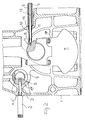
- Fig. 1 "a” shows an axial section on a crankcase 1, in which a crankshaft 7 is embedded.
- a stop surface 23 is provided on the side of a crank web, with a bore 21 which is axially aligned with a threaded bore 24 on the crankcase.
- the setting pin 20 is screwed in through the threaded bore 24 on the crankcase until its stepped surface 25 rests on the crankcase and its tip engages in the bore 21.
- the crankshaft can thus be held in the desired position.
- the outer part of the setting pin is knurled to enable it to be installed and removed.
- Variant "b” differs from variant “a” only in that the bore 22 into which the adjusting pin 20 engages has more play than in the bore 21, which is easier and more economical to manufacture.
- Figure 2 shows in axial section a crankcase part 1 of an internal combustion engine with a camshaft 6 and the crankshaft 7 mounted therein.
- the crankcase has a bore 4 at the level of the camshaft, the initial part 4 'is provided with an internal thread.
- a threaded hole 15 is also provided in the crankcase at the level of the upper part of the crankshaft.
- the camshaft has a bore 5 which is flush with the bore 4 when the camshaft is brought into the position which is decisive for the adjustment of the timing.
- the setting pin 2 is pushed and tightened on the threaded part 4 '.
- the tip of the offset part 3 of the adjusting pin engages in the bore 5 and holds the camshaft 6 in its position immovably.
- the end of the adjusting pin When screwed in, the end of the adjusting pin snaps into the camshaft bore smoothly and without play and locks the camshaft firmly in the position intended for adjustment. Increased security against twisting is achieved by creating the offset Level of the adjusting pin on the crankcase reached.
- the adjustment pin is knurled or has a hexagon head or a slot to facilitate the installation or rotation of this part in the crankcase.
- a threaded hole is provided on the crankcase at the level of the crankshaft upper part, through which a stop sleeve 9 with an outer diameter is screwed.
- the threaded part 11 of the stop sleeve lies at the beginning of the offset piece and is dimensioned such that the stop sleeve bears in the installed state with the offset surface on the outer crankcase wall, while at the same time the end part lies on the flattened area around the threaded bore 14 on the crankshaft 8. This ensures the highest level of security against torsion.
- any macro movement that may occur due to the force of the crankshaft can be eliminated by magnetically activating the tip of the setting pin 13 within the threaded bore 14.
- the adjusting sleeve is also knurled or provided with a hexagon head to facilitate installation.
- the driving crankshaft and the driven camshaft are brought into immovable position by the two adjusting pins and the stop sleeve.
- the power transmission Element, chain or wheel drive, can then be attached to the immovably fixed shafts.
- Block or distributor injection pumps can also be set correctly in the same way with a fixed blocking of the intended setting position.
- the stop pins and the stop sleeve are removed and the openings on the crankcase are closed with a locking screw.
Landscapes
- Engineering & Computer Science (AREA)
- Mechanical Engineering (AREA)
- General Engineering & Computer Science (AREA)
- Valve-Gear Or Valve Arrangements (AREA)
Claims (5)
- Dispositif pour l'ajustage du calage de la distribution d'un moteur à combustion interne, avec un arbre de vilebrequin (7), qui est monté dans un carter de vilebrequin (1), et avec au moins un arbre à cames (6), qui est disposé dans le carter de vilebrequin (1) ou bien dans une culasse et qui est entraîné par l'arbre de vilebrequin (7), tandis que l'arbre à cames (6) et l'arbre de vilebrequin (7) sont susceptibles d'être fixés dans leur position de rotation et qu'une broche de fixation (2) est susceptible, dans la position d'ajustage de l'arbre à cames (6), d'être enfoncée, sans jeu mais facilement, dans un perçage radial (5) de l'arbre à cames à travers un perçage latéral (4) dans le carter (1) du vilebrequin ou dans la culasse, dans la zone d'un palier (17) de l'arbre à cames, dispositif caractérisé en ce que l'arbre de vilebrequin (7) comporte un perçage défini (21), qui est disposé à une certaine distance de l'axe de rotation de l'arbre de vilebrequin (7) sur un flasque (18) du vilebrequin, et en ce que le carter (1) du vilebrequin comporte un perçage fileté (24) aligné sur le perçage (21) dans l'arbre (7) du vilebrequin, en ce qu'il est prévu une broche d'ajustage (20), qui est susceptible d'être vissée dans le perçage fileté (24) du carter (1) du vilebrequin et qui vient alors en prise par sa pointe dans le perçage (21) de l'arbre (7) du vilebrequin.
- Dispositif selon la revendication 1, caractérisé en ce que la broche d'ajustage (20) vient en prise avec du jeu dans le perçage (21) de l'arbre (7) du vilebrequin, en ce que l'extrémité de la broche d'ajustage (20) forme une butée avec le fond du perçage de l'arbre (7) du vilebrequin, et en ce que la broche d'ajustage (20) comporte un tronçon (19) avec un épaulement (25) qui, dans la position de montage, s'applique contre une surface définie (26) de la face externe du carter (1) du vilebrequin.
- Dispositif selon la revendication 2, caractérisé en ce que la pointe de la broche d'ajustage (20) est magnétique.
- Dispositif pour l'ajustage du calage de la distribution d'un moteur à combustion interne, avec un arbre de vilebrequin (7), qui est monté dans un carter de vilebrequin (1), et avec au moins un arbre à cames (6), qui est disposé dans le carter de vilebrequin (1) ou bien dans une culasse et qui est entraîné par l'arbre de vilebrequin (7), tandis que l'arbre à cames (6) et l'arbre de vilebrequin (7) sont susceptibles d'être fixés dans leur position de rotation et qu'une broche de fixation (2) est susceptible, dans la position d'ajustage de l'arbre à cames (6), d'être enfoncée, sans jeu mais facilement, dans un perçage radial (5) de l'arbre à cames à travers un perçage latéral (4) dans le carter (1) du vilebrequin ou dans la culasse, dans la zone d'un palier (17) de l'arbre à cames, dispositif caractérisé en ce que l'arbre (7) du vilebrequin comporte une surface de butée définie (8) et un perçage (14) qui sont disposés à une certaine distance de l'axe de rotation de l'arbre (7) du vilebrequin sur un flasque (18) du vilebrequin et en ce qu'il est prévu une douille de butée (9) qui est susceptible d'être vissée dans un perçage fileté (15), aligné sur le perçage (14) du carter (1) du vilebrequin, douille qui comporte un épaulement s'appliquant contre une surface définie de la face externe du carter (1) du vilebrequin et s'applique, en outre, par sa partie terminale contre la surface de butée (8) de l'arbre (7) du vilebrequin, et en ce qu'une broche d'ajustage (13) est susceptible d'être introduite dans la douille de butée (9), broche dont la pointe fait saillie dans le perçage (14) de l'arbre (7) du vilebrequin.
- Dispositif selon la revendication 4, caractérisé en ce que la broche d'ajustage (13) porte à sa pointe un filetage et est ainsi susceptible d'être vissée dans le perçage (14) de l'arbre (7) du vilebrequin, tandis qu'un épaulement de la broche d'ajustage (13) prend appui sur l'extrémité, éloignée de l'arbre du vilebrequin, de la douille de butée (9).
Applications Claiming Priority (2)
| Application Number | Priority Date | Filing Date | Title |
|---|---|---|---|
| DE3832812A DE3832812A1 (de) | 1988-09-28 | 1988-09-28 | Vorrichtung zur einstellung der steuerzeiten an einer brennkraftmaschine, deren nockenwelle ueber einen zahnriemen, eine kette oder auch einen zahnraedertrieb angetrieben wird |
| DE3832812 | 1988-09-28 |
Publications (2)
| Publication Number | Publication Date |
|---|---|
| EP0362687A1 EP0362687A1 (fr) | 1990-04-11 |
| EP0362687B1 true EP0362687B1 (fr) | 1993-10-20 |
Family
ID=6363828
Family Applications (1)
| Application Number | Title | Priority Date | Filing Date |
|---|---|---|---|
| EP89117918A Expired - Lifetime EP0362687B1 (fr) | 1988-09-28 | 1989-09-28 | Dispositif pour l'ajustage du calage de la distribution d'un moteur à combustion interne dont l'arbre à cames et entraîné par courroie, chaîne ou engrenage |
Country Status (3)
| Country | Link |
|---|---|
| US (1) | US5099563A (fr) |
| EP (1) | EP0362687B1 (fr) |
| DE (2) | DE3832812A1 (fr) |
Families Citing this family (18)
| Publication number | Priority date | Publication date | Assignee | Title |
|---|---|---|---|---|
| US5845397A (en) * | 1997-02-21 | 1998-12-08 | Cummins Engine Company, Inc. | Static timing method for heavy duty diesel engines |
| US5950294A (en) * | 1998-03-17 | 1999-09-14 | Gibbs; Joseph L. | Tool for immobilizing cam shaft gears |
| JP2000304010A (ja) | 1999-02-10 | 2000-10-31 | Nsk Ltd | 被固定部材の固定部材への取り付け構造 |
| DE19919660A1 (de) * | 1999-04-29 | 2000-11-02 | Volkswagen Ag | Verfahren und Vorrichtung zum vorübergehenden Arretieren einer Kurbelwelle |
| GB2392711B (en) | 2002-09-03 | 2004-08-18 | Auto Service Tools Ltd | Holding device |
| BR0302062B1 (pt) * | 2003-05-30 | 2011-12-13 | motor de combustão interna e carcaça de motor. | |
| FR2855553B1 (fr) * | 2003-06-02 | 2007-06-08 | Inst Francais Du Petrole | Moteur a combustion interne a culasse mobile, notamment moteur pour essais |
| AT501132B1 (de) * | 2004-11-11 | 2006-11-15 | Avl List Gmbh | Brennkraftmaschine |
| FR2897400B1 (fr) * | 2006-02-10 | 2009-06-05 | Renault Sas | Piece de blocage d'un volant moteur |
| DE102010055192B4 (de) | 2010-12-20 | 2024-05-02 | Volkswagen Aktiengesellschaft | Verbrennungsmotor mit Führung zum Abstecken der Nockenwelle sowie Verschlusselement |
| US8776741B2 (en) * | 2011-03-03 | 2014-07-15 | GM Global Technology Operations LLC | Engine assembly including cam phaser assembly aid pin |
| DE102011121860A1 (de) | 2011-12-21 | 2013-06-27 | Volkswagen Aktiengesellschaft | Verbrennungsmotor mit Öffnung zum Abstecken einer Welle und Geberelement zur Erfassung der Winkellage der Welle |
| US20140290626A1 (en) * | 2013-03-28 | 2014-10-02 | Caterpillar Inc. | Assembling fuel pump on engine |
| DE102014104995A1 (de) * | 2014-04-08 | 2015-10-08 | Thyssenkrupp Presta Teccenter Ag | Modul mit vororientierter Nockenwelle |
| CN104329168A (zh) * | 2014-09-05 | 2015-02-04 | 朝柴动力科技(北京)有限公司 | 发动机一缸活塞上止点锁止机构 |
| DE102016112994A1 (de) | 2016-07-14 | 2018-01-18 | Thyssenkrupp Ag | Montagehilfe, Nockenwellenmodul und Verfahren zur Fixierung der Drehposition von drehbar gelagerten Wellen |
| DE102016217356B4 (de) | 2016-09-12 | 2021-02-18 | Volkswagen Aktiengesellschaft | Vorrichtung zur vorübergehenden relativen drehfesten Arretierung von zwei Nockenwellen |
| FR3077843B1 (fr) * | 2018-02-15 | 2022-05-13 | Psa Automobiles Sa | Dispositif de calage pour arbre a cames |
Family Cites Families (6)
| Publication number | Priority date | Publication date | Assignee | Title |
|---|---|---|---|---|
| US4232497A (en) * | 1979-02-21 | 1980-11-11 | Albin Meschnig | Device for securing platelike elements to a carrying structure at a distance therefrom |
| DE3131278A1 (de) * | 1981-08-07 | 1983-02-24 | Bayerische Motoren Werke AG, 8000 München | Verfahren und vorrichtung zum einstellen der ventilsteuerung einer hubkolben-brennkraftmaschine, insbes. eines diesel-motors |
| DE3629431A1 (de) * | 1986-08-29 | 1988-03-03 | Porsche Ag | Vorrichtung zum einstellen von raedern eines kraftfahrzeugs, insbesondere zum einstellen eines radsturzes |
| US4796494A (en) * | 1987-03-30 | 1989-01-10 | Eaton Corporation | Headlight position adjustment assembly |
| SE458137B (sv) * | 1987-05-13 | 1989-02-27 | Volvo Ab | Foerfarande och anordning vid en bilmotor med dubbla kamaxlar |
| US4957317A (en) * | 1990-04-27 | 1990-09-18 | Taurus Precision, Inc. | Drum lock device |
-
1988
- 1988-09-28 DE DE3832812A patent/DE3832812A1/de not_active Withdrawn
-
1989
- 1989-09-14 US US07/407,101 patent/US5099563A/en not_active Expired - Fee Related
- 1989-09-28 EP EP89117918A patent/EP0362687B1/fr not_active Expired - Lifetime
- 1989-09-28 DE DE89117918T patent/DE58905960D1/de not_active Expired - Fee Related
Also Published As
| Publication number | Publication date |
|---|---|
| US5099563A (en) | 1992-03-31 |
| DE58905960D1 (de) | 1993-11-25 |
| EP0362687A1 (fr) | 1990-04-11 |
| DE3832812A1 (de) | 1990-03-29 |
Similar Documents
| Publication | Publication Date | Title |
|---|---|---|
| EP0362687B1 (fr) | Dispositif pour l'ajustage du calage de la distribution d'un moteur à combustion interne dont l'arbre à cames et entraîné par courroie, chaîne ou engrenage | |
| EP0254058A2 (fr) | Arbre à cames pour le réglage des soupapes d'admission et d'échappement d'un moteur à combustion interne | |
| DE3242862C2 (fr) | ||
| WO2008125565A1 (fr) | Arbre à cames | |
| DE10161701A1 (de) | Vorrichtung zum Verändern der Steuerzeiten von Gaswechselventilen einer Brennkraftmaschine, insbesondere Einrichtung zur hydraulischen Drehwinkelverstellung einer Nockenwelle gegenüber einer Kurbelwelle | |
| DE3039946A1 (de) | Vorrichtung zur verhinderung des verdrehens von stoesseln bei verbrennungskraftmaschinen | |
| DE20313211U1 (de) | Haltevorrichtung | |
| DE102011121860A1 (de) | Verbrennungsmotor mit Öffnung zum Abstecken einer Welle und Geberelement zur Erfassung der Winkellage der Welle | |
| EP0090226B1 (fr) | Procédé et dispositif de montage d'une pompe d'injection sur un moteur à combustion interne | |
| DE3926430C2 (de) | Verfahren und Vorrichtung zum phasenrichtigen Einstellen von Nockenwellen | |
| DE19820638A1 (de) | Zahnradanordnung | |
| DE102016101264B3 (de) | Nockenwelleneinstellwerkzeug | |
| DE102004035077A1 (de) | Verfahren zum Einstellen einer Nockenwellenverstelleinrichtung für Brennkraftmaschinen von Kraftfahrzeugen sowie Vorrichtung zur Durchführung des Verfahrens | |
| DE4139446C2 (fr) | ||
| DE69925426T2 (de) | Vorrichtung zum Ausrichtung von Nockenwelle und Vehrfahren zu dessem Betrieb | |
| EP2664752A1 (fr) | Procédé de compensation d'une modification de distance d'axe sur la distribution d'un moteur à combustion interne commandé par soupape et distribution | |
| EP0725213B1 (fr) | Module de montage pour la commande d'arbre à came pour le montage prépositionné dans un moteur à combustion interne | |
| DE3813703A1 (de) | Ventilspieleinsteller und verfahren zur einstellung des ventilspiels | |
| DE102010055192B4 (de) | Verbrennungsmotor mit Führung zum Abstecken der Nockenwelle sowie Verschlusselement | |
| DE2935423A1 (de) | Befestigungsvorrichtung fuer einen mehrspindelkopf einer bearbeitungsmaschine | |
| DE3541700A1 (de) | Brennkraftmaschine mit mindestens einer obenliegenden nockenwelle | |
| EP1048824A2 (fr) | Moteur à combustion interne avec entraínement frontal aux roues dentées | |
| EP0947670B1 (fr) | Entraînement d'arbre à cames d'un moteur à combustion interne | |
| DE3875123T2 (de) | Vorrichtung und verfahren zur regelung von nokkenwellen. | |
| DE4130125C2 (de) | Mechanische Handverstelleinrichtung für den Regelhub eines Stellgliedes |
Legal Events
| Date | Code | Title | Description |
|---|---|---|---|
| PUAI | Public reference made under article 153(3) epc to a published international application that has entered the european phase |
Free format text: ORIGINAL CODE: 0009012 |
|
| AK | Designated contracting states |
Kind code of ref document: A1 Designated state(s): DE FR GB IT |
|
| 17P | Request for examination filed |
Effective date: 19900303 |
|
| 17Q | First examination report despatched |
Effective date: 19910621 |
|
| RAP1 | Party data changed (applicant data changed or rights of an application transferred) |
Owner name: KLOECKNER-HUMBOLDT-DEUTZ AG |
|
| GRAA | (expected) grant |
Free format text: ORIGINAL CODE: 0009210 |
|
| AK | Designated contracting states |
Kind code of ref document: B1 Designated state(s): DE FR GB IT |
|
| PG25 | Lapsed in a contracting state [announced via postgrant information from national office to epo] |
Ref country code: IT Free format text: LAPSE BECAUSE OF FAILURE TO SUBMIT A TRANSLATION OF THE DESCRIPTION OR TO PAY THE FEE WITHIN THE PRE;WARNING: LAPSES OF ITALIAN PATENTS WITH EFFECTIVE DATE BEFORE 2007 MAY HAVE OCCURRED AT ANY TIME BEFORE 2007. THE CORRECT EFFECTIVE DATE MAY BE DIFFERENT FROM THE ONE RECORDED.SCRIBED TIME-LIMIT Effective date: 19931020 Ref country code: FR Effective date: 19931020 |
|
| REF | Corresponds to: |
Ref document number: 58905960 Country of ref document: DE Date of ref document: 19931125 |
|
| GBT | Gb: translation of ep patent filed (gb section 77(6)(a)/1977) |
Effective date: 19931029 |
|
| EN | Fr: translation not filed | ||
| PLBE | No opposition filed within time limit |
Free format text: ORIGINAL CODE: 0009261 |
|
| STAA | Information on the status of an ep patent application or granted ep patent |
Free format text: STATUS: NO OPPOSITION FILED WITHIN TIME LIMIT |
|
| 26N | No opposition filed | ||
| PGFP | Annual fee paid to national office [announced via postgrant information from national office to epo] |
Ref country code: GB Payment date: 20010817 Year of fee payment: 13 |
|
| REG | Reference to a national code |
Ref country code: GB Ref legal event code: IF02 |
|
| PG25 | Lapsed in a contracting state [announced via postgrant information from national office to epo] |
Ref country code: GB Free format text: LAPSE BECAUSE OF NON-PAYMENT OF DUE FEES Effective date: 20020928 |
|
| PGFP | Annual fee paid to national office [announced via postgrant information from national office to epo] |
Ref country code: DE Payment date: 20020930 Year of fee payment: 14 |
|
| GBPC | Gb: european patent ceased through non-payment of renewal fee |
Effective date: 20020928 |
|
| PG25 | Lapsed in a contracting state [announced via postgrant information from national office to epo] |
Ref country code: DE Free format text: LAPSE BECAUSE OF NON-PAYMENT OF DUE FEES Effective date: 20040401 |