EP0363497A1 - Pompe d'adsorption cryogenique - Google Patents
Pompe d'adsorption cryogenique Download PDFInfo
- Publication number
- EP0363497A1 EP0363497A1 EP89903491A EP89903491A EP0363497A1 EP 0363497 A1 EP0363497 A1 EP 0363497A1 EP 89903491 A EP89903491 A EP 89903491A EP 89903491 A EP89903491 A EP 89903491A EP 0363497 A1 EP0363497 A1 EP 0363497A1
- Authority
- EP
- European Patent Office
- Prior art keywords
- vessel
- pump
- housing
- radiation shield
- pumping element
- Prior art date
- Legal status (The legal status is an assumption and is not a legal conclusion. Google has not performed a legal analysis and makes no representation as to the accuracy of the status listed.)
- Withdrawn
Links
Images

Classifications
-
- F—MECHANICAL ENGINEERING; LIGHTING; HEATING; WEAPONS; BLASTING
- F04—POSITIVE - DISPLACEMENT MACHINES FOR LIQUIDS; PUMPS FOR LIQUIDS OR ELASTIC FLUIDS
- F04B—POSITIVE-DISPLACEMENT MACHINES FOR LIQUIDS; PUMPS
- F04B37/00—Pumps having pertinent characteristics not provided for in, or of interest apart from, groups F04B25/00 - F04B35/00
- F04B37/06—Pumps having pertinent characteristics not provided for in, or of interest apart from, groups F04B25/00 - F04B35/00 for evacuating by thermal means
- F04B37/08—Pumps having pertinent characteristics not provided for in, or of interest apart from, groups F04B25/00 - F04B35/00 for evacuating by thermal means by condensing or freezing, e.g. cryogenic pumps
-
- Y—GENERAL TAGGING OF NEW TECHNOLOGICAL DEVELOPMENTS; GENERAL TAGGING OF CROSS-SECTIONAL TECHNOLOGIES SPANNING OVER SEVERAL SECTIONS OF THE IPC; TECHNICAL SUBJECTS COVERED BY FORMER USPC CROSS-REFERENCE ART COLLECTIONS [XRACs] AND DIGESTS
- Y10—TECHNICAL SUBJECTS COVERED BY FORMER USPC
- Y10S—TECHNICAL SUBJECTS COVERED BY FORMER USPC CROSS-REFERENCE ART COLLECTIONS [XRACs] AND DIGESTS
- Y10S417/00—Pumps
- Y10S417/901—Cryogenic pumps
Definitions
- the invention relates to vacuum technology and in particular to cryogenic adsorption pumps and can be used to generate an ultra-pure oil-free vacuum in a pressure range of 10 2 to 10 -7 Pa when evacuating any, including aggressive gases, helium, in chambers of various purposes with a volume of 0.01 m 3 can be used up to several hundreds of cubic meters.
- a cryogenic adsorption pump with a pumping element is known (SU, A, 1333833), which consists of an annular vessel with liquid nitrogen, a porous screen which is arranged coaxially with the vessel in a space which is enclosed by the inner side surface of the vessel and an adsorbent, which is housed in a gap between the inner side surface of the vessel and the porous screen.
- a disadvantage of this pump is that, at the liquid nitrogen temperature, the adsorbent has a low sorption capacity at low (below 10 -3 to 10 -4 Pa) equilibrium pressures of the adsorbed gases. This is why this pump cannot achieve any limit pressures below 10- 3 Pa even after a brief exposure to the leg.
- the adsorbent is cooled by solid nitrogen up to temperatures of 55 to 50 K.
- the heating of nitrogen causes after its vapors have been evacuated. Operation of the pump is made more difficult by the fact that one often has to fill the vessel with liquid nitrogen and repeatedly pump out its vapors.
- a cryogenic adsorption pump is also known. (Zhurnal tekhnicheskoj fiziki, volume 28, issue 10, 1988, October, Nauka (Leningrad branch), MPLarin "Kondensatsionno-adsorbtsionnaya und sorbtsionnaya otkachka pri Temperaturakh twerdogo azota", p.2026 to 2039), with a housing with a cover that one is provided to be evacuated volume with a inlet connection for connection, and the housing is accommodated a pump-out element and a cooled radiation shield of the pump-out umschli - eat.
- the pumping element is designed as an annular cryogenic agent vessel, to the bottom of which a disk-shaped heat conductor is welded, and as heat-conducting frames and frame-porous screens, which are arranged coaxially to the vessel and are attached to the disk-shaped heat conductor. Cavities between the heat-conducting frames and the frame-porous screens adjacent to them are filled with adsorbent, and cavities between adjacent frame-porous screens are connected to the inlet connection of the pump.
- the radiation umbrella contains a toroidal cryogenic agent vessel which is arranged under the vessel of the pumping element, a frame which is arranged coaxially with the pumping element and an arrow screen which is arranged between the pumping element and the inlet connection.
- the lower end of the frame of the radiation shield is attached to the vessel of the radiation shield in an airtight manner and in its upper part the frame has a lid which is connected to the inlet connector via a corrugated tube-like thermal bridge.
- In the housing there is a nozzle for evacuating a space between the housing and the radiation shield.
- the pump also contains a thin-walled tube, which is arranged in a space delimited by inner walls of the vessel of the radiation shield and is airtightly attached to the lid of this vessel at the upper end and to the bottom of the housing at the lower end.
- the tube cross-section is bridged by an arrow screen, which has thermal contact with the vessel of the radiation screen.
- the vessel of the radiation shield When operating the pump, the vessel of the radiation shield is filled with liquid nitrogen and the vessel of the pumping element with solid nitrogen, i.e. filled with a cryogen at a lower temperature.
- the radiation screen cooled down to a temperature of 77.4 K by liquid nitrogen sets.
- a heat supply by radiation from the housing into the pumping element is considerably reduced, thanks to which nitrogen in the solid state can be held for a longer, dozen times longer than in the pump described above when the adsorbent is cooled by solid nitrogen.
- a space between the thin-walled tube, an inner wall of the vessel of the radiation shield, the bottom of this vessel, its outer wall, the frame of the radiation shield and the pump housing forms the so-called protective vacuum space.
- a pressure of less than 10 -4 Pa is set in this room, as a result of which the heat input from residual gases from the housing into the radiation shield is greatly reduced.
- the invention has for its object to provide a cryogenic adsorption pump, wherein at inlet pressures above 10 -2 Pa no noticeable heat exchange through the gases to be evacuated between the pumping element, which is cooled by a cryogen with a lower temperature, and the radiation shield, the is cooled by a cryogen at a higher temperature, which increases the operating efficiency of the pump at these pressures, as well as a reduced cryogen consumption for cooling the pumping element and a reduction in the amount of work required to maintain the pump in the operating state.
- This task is based on a cryogenic adsorption pump with a housing with an inlet connection and the pumping element arranged in the housing, containing an adsorbent and a vessel for cryogenic agents with a lower temperature, a radiation shield which encloses the pumping element and a toroidal vessel for cryogenic agents with one higher temperature and a frame, which is connected at the lower end to this vessel and at the upper end to the housing, and a thin-walled tube, which is arranged in a space delimited by the inner wall of the radiation shield and at the lower end airtight with the housing bottom .
- a thermal bridge which is arranged between the frame of the radiation shield and the pumping element and at the upper end. the upper part of the frame is connected over its entire circumference and at the lower end to the vessel of the pumping element over its entire circumference, the upper tube end being airtightly connected to the vessel of the pumping element.
- the frame of the radiation shield has openings which connect a space between the housing and the "radiation shield” with a space between the radiation shield and the thermal bridge.
- the pump additionally contains a toroidal vessel which is arranged in the interior of the vessel of the radiation shield and has two connecting pieces which are led out of the housing in an airtight manner.
- this vessel the working chamber can be temporarily evacuated with the help of a conventional backing pump without the risk that the volume to be evacuated will be contaminated by oil vapors from this backing pump.
- this additional vessel plays the role of a stiocarbon, which is built into the cryogenic center vessel of the radiation shield.
- the pump may include two emergency valves connected to the inlet port, the first of which communicates with the outside air and the second communicates with a space between the housing and the radiation shield.
- valves increase the operational reliability of the pump by protecting the thin-walled thermal bridge from destruction in the event of an accident.
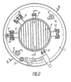
- the cryogenic adsorption pump has a housing (FIG. 1) with a cover 2, which is provided with an inlet connection 3.
- a pump-out element is arranged in the housing 1, containing a toroidal cryogen container 4, on the cover 5 of which coaxially arranged heat-conducting frames 6, 7 and 8 and frame-porous screens 9 are welded.
- the outer heat-conducting frame 6 and the inner heat-conducting frame 8 are made of dense sheet metal and the other heat-conducting frames 7 are perforated. As a material for the frames 9, for example. porous copper can be used.
- the outer porous screen 9 is on the inside of the heat-conducting frame 6, the inner porous screen is on the outside of the heat-conducting frame 8 and the other porous screens 9 are arranged on both sides of the perforated heat conductor 7.
- Annular spaces ' 10 between the heat-conducting frames 6, 7 and 8 and the adjacent porous screens 9 are with an adsorbent. eg activated carbon filled.
- a perforation in heat conductors 7, which are surrounded by adsorbents from the two sides, is carried out to accelerate the process of balancing the equilibrium pressure of the gases over the adsorbent.
- the rooms 10 are covered by rings 11 from above.
- Annular spaces 12 between adjacent porous screens 9 serve for the passage of the evacuated gases.
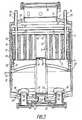
- tubes 13 (Fig. 2, 3) are welded airtight, which are connected to its space.
- the upper ends of these tubes 13 are led out of the housing 1 and fastened in the cover 2 via connecting pieces 14.
- the tubes 13 are used for filling cryogen into the vessel 4 and for evacuating the cryogen vapors in order to lower the cryogen temperature in the vessel 4.
- the pump-off element is enclosed by a radiation shield to reduce heat input from the housing.1.
- the radiation shield contains a toroidal vessel 15 (FIGS. 1, 3) for cryogen with a temperature above that of the cryogen in the vessel 4 of the pumping element, a frame 16 and an arrow screen 17.
- the vessel 15 is arranged under the vessel 4 of the pumping element and the Frame 16 is attached to the vessel 15 airtight at the lower end.
- Two tubes 18 and 19 (FIG. 1) are inserted into the vessel 15 of the radiation shield, of which the tube 18 is used to fill the vessel 15 with cryogen and the tube 19 is used to evacuate the cryogen vapors.
- the frame 16 has a cover 20 which is attached to the inlet connection 3 via a corrugated tube-like thermal bridge 21.
- Sockets 22 are welded to the cover 20, the upper ends of which are welded to the tubes 13 and the sockets 14 in a vacuum-tight manner.
- the arrow screen 17 is arranged between the pumping element and the inlet connection 3 and is fastened to the upper part of the frame 16 with good thermal contact.
- An additional screen 23 is arranged between the housing 1 ' and the radiation screen, which screen is intended to reduce the supply of heat by radiation from the housing 1 into the radiation screen.
- the pump contains a vacuum-tight thermal bridge 24, which is designed as a thin-walled frame and is arranged between the frame 16 of the radiation shield and the pumping element. At the upper end, the thermal bridge 24 is connected to the upper part of the frame 16 over its entire circumference and at the lower end to the vessel 4 of the pumping element also over its entire circumference.
- the thermal bridge 24 is made of a thin stainless steel strip with a thickness of about 0.15 to 0.2 mm, so that its cross-sectional area is as small as possible, and with many beads to increase its actual length. This design of the thermal bridge 24 ensures a reduction in the supply of heat by thermal conductivity from the frame 16 of the radiation shield into the pumping element.
- the pump also contains a thin-walled tube 25 which runs in a space between the inner walls of the vessels 4 and 15.
- the upper end of the tube 25 is connected to the lid 5 of the vessel 4 and the lower end of a corrugated pipe 26 having a flange 27 hermetically, which is welded to the bottom 28 of the overall äuses h. 1
- an arrow screen 29 Arranged in the lower part of the tube 25 is an arrow screen 29, which is connected to the bottom of the vessel 15 via a ring 30 with good thermal contact.
- a connection with a valve 34 (FIG. 2), which is arranged on the cover 2 of the housing, is used to connect a backing pump to the protective vacuum chamber 31.
- the spaces 31 and 36 are connected to one another via openings 37 which are embodied in the frame 16.
- the openings 37 present in the frame 16 are not a mandatory condition for the implementation of the invention. If none of these openings are present, the construction of the pump according to the invention and its preparation for operation are made to a certain extent more complicated, because in this case the housing 1 is equipped with an additional stopper for evacuating the To provide room 36 between the thermal bridge 24 and the radiation shield, and in this room an element with adsorbent to maintain a required vacuum in this room has to be installed.
- the interconnected spaces 31 and 36 can be evacuated simultaneously via a nozzle with the valve 34 (FIG. 2) and adsorbent, which is located in the annular recess 3S. (Fig.1) the frame 16 is located, ensures a required vacuum in both room 31 and in room 46.
- a toroidal vessel 38 Arranged in the interior of the vessel 15 of the radiation shield is a toroidal vessel 38, which has nozzles 39 (FIG. 3) which are connected in an airtight manner to corrugated tubes 40, which in turn are connected to the bottom 28 of the pump housing via nozzles with attachable flanges.
- This vessel 38 performs the functions of a nitrogen avalanche when the working chamber is pre-evacuated. With the help of a backing pump and prevents oil from entering this pump into the volume to be evacuated.
- one of these attachable flanges is connected via a valve to a mechanical backing pump and the other also via a valve to the chamber to be evacuated.
- connection 41 In the walls of the inlet connection 3 there are connections 41 (FIGS. 1, 2), 42 and 43.
- An emergency valve 44 is connected to one of the connectors 41, which connects the pump chamber to the outside air
- an emergency valve 45 is connected to the other connector 41, which connects the pump chamber to the protective vacuum chamber 31 via a connector 46.
- the connecting piece 42 is intended for connecting pressure transmitters for measuring a fore and a high vacuum
- the connecting piece 43 is intended for connecting a fore vacuum pump via a valve when the working chamber is evacuated.
- the emergency valves 44 and 45 prevent destruction of the thermal bridge 24 (Fig. 1, 3) in emergency situations, which has a relatively large diameter and a small wall thickness and is therefore one of the most endangered pump elements in terms of mechanical strength.
- disks 47 (FIG. 1) and 48 with openings 49 and 50 are arranged along its vertical axis, and the arrow screens 17 and 29 have openings 51 and 52 for inserting a transport rod, which are connected to the opening by means of a threaded connection 50 of the disc 48 and in the discs 53, 54 is attached.
- the inlet connection 3 and the flange 27 are closed by blind flanges 55 and 56, respectively
- All surfaces of the pump elements facing the space to be evacuated have a two-layer coating of a dense aluminum layer with a thickness of not less than 1 ⁇ m and an aluminum oxide layer with a thickness of 2 to 20 nm.
- the arrow screens 17 and 29 have coatings with a thickness not less than 200 ⁇ m with a degree of blackening not less than 0.99 in a wavelength range from 2 to 200 ⁇ m.
- the pump according to the invention works as follows.
- a mechanical backing pump is connected to the connecting pieces 43 (FIG. 2) and 34 and the pump chamber and the protective vacuum chambers 31 (FIG. 1) and 36 are evacuated at the same time. Said rooms are to be evacuated at the same time with the purpose that a pressure difference in the pump room and in the protective vacuum rooms 31 and 36 is not higher than 2.10 4 Pa and that there is no destruction of the thermal bridge 24 or membrane breakthrough in the valves 44 and 45 can.
- the evacuation is interrupted and a cryogen, for example liquid nitrogen, is poured into the vessel 15 of the radiation shield via the tube 18.
- a cryogen for example liquid nitrogen
- adsorbent is also cooled, which is in the annular Recess 32 of the frame 16 is located. This causes a pressure reduction in the protective vacuum spaces 31 and 36 up to 10 -4 Pa and a strong reduction in heat exchange by residual gases between the housing 1 and the radiation shield and between the latter and the pumping element.
- the working chamber is separated from the pump by the closure, it is connected via a valve (not shown) to one of the attachable flanges connected to the corrugated tube 40 (FIG. 3), and the second attachable flange is closed also via a valve to the mechanical backing pump and evacuates the chamber via the vessel '3 8 to a pressure of approx. 1 Pa.
- the vessel 38 acts as a nitrogen all for oil vapors of the fore-vacuum pump and prevents it from entering the volume to be evacuated. This ends the process of pre-evacuating the work chamber.
- a cryogen with a lower temperature than that of the cryogen in vessel 15 of the radiation screen e.g. Liquid hydrogen or helium or the same cryogen.
- the temperature of the cryogen in the vessel 5 is reduced by evacuating its vapors via the pipe 13 with the help of the forevacuum pump.
- the nitrogen temperature in the vessel 5 is reduced to 55 K after two hours of their work and after a further four hours of evacuation to 50 K and below.
- the liquid nitrogen hardens at a temperature of 63 K.
- adsorbent Simultaneously with the vessel 5 is cooled via the heat conductors 6, 7 and 8 adsorbent, which is located in the annular spaces 10 of the pumping element.
- Adsorbent swallows the gases coming out of the working chamber and ensures a limit pressure of 10 -7 Pa and below.
- the sorption capacity of an adsorbent increases by several orders of magnitude in comparison with its sorption capacity at the temperature of the Liquid Stiokstoffes (77.4 K) or the equilibrium pressure is reduced by several orders of magnitude after adsorption of one and the same amount of gas.
- the pump is ready for operation and a high vacuum evacuation of the working chamber can be carried out by opening the closure which connects it to the pump.
- the non-adsorbable gases such as helium and neon are removed with the help of an ion atomizing pump; which is connected to the flange 27.
- valves 44 (FIG. 2) and 45 are provided. If the pressure in the pump room exceeds the pressure in the protective vacuum rooms 31 (Fig. 1) and 36 ⁇ m, for example 2.10 4 Pa, the valve 45 (Fig. 2) responds and the pressure in these rooms is equalized. The valve 44 responds as soon as the pressure in the pump chamber also exceeds the atmospheric pressure by 2.10 4 Pa, and connects the pump chamber to the outside air.
- the thermal bridge 24 (FIG. 1), which is arranged between the pumping element and the frame 16 of the radiation shield, is the source of a certain heat supply into the pumping element due to its thermal conductivity, it enables the pumping element to be protected by a protective vacuum from the side of the frame 16 of the Radiation screen and surround from the side of the lid 35 of its vessel 15. Therefore, the heat supply caused by heat exchange with residual gases at working pressures above 10-2 Pa is excluded from the radiation shield into the pumping element and the total heat supply into the pumping element is reduced accordingly.
- the working time of a pumping element is 300 hours until a required refilling with liquid nitrogen and 50 hours at an inlet pressure of 1 Pa.
- the invention can be used for evacuating plants for vapor deposition and plasma-chemical plants, for example in the electronics industry, and for producing an ultra-pure oil-free vacuum in a pressure range from 10 2 to 10 -7 Pa when solving several tasks in vacuum technology.
Landscapes
- Engineering & Computer Science (AREA)
- Mechanical Engineering (AREA)
- General Engineering & Computer Science (AREA)
- Compressors, Vaccum Pumps And Other Relevant Systems (AREA)
- Structures Of Non-Positive Displacement Pumps (AREA)
- Nitrogen And Oxygen Or Sulfur-Condensed Heterocyclic Ring Systems (AREA)
- Filling Or Discharging Of Gas Storage Vessels (AREA)
Abstract
La pompe d'adsorption cryogénique décrite comprend un élément d'aspiration avec un réservoir (4) pour l'agent cryogénique de température inférieure, un écran absorbant le rayonnement qui renferme l'élément d'aspiration, un tube (25) et un pont thermique (24). L'écran absorbant le rayonnement comprend un réservoir (15) pour l'agent cryogénique de température supérieure, une enveloppe (16) reliée par son extrémité supérieure au réservoir (15) et par son extrémité inférieure au réservoir (4) de l'élément d'aspiration. Le tube (25) traverse un espace libre situé entre les parois internes des réservoirs (4 et 15) et est relié par son extrémité inférieure à la partie inférieure (28) d'un logement (1) et par son extrémité supérieure au réservoir (4) de l'élément d'aspiration. Lors du fonctionnement de la pompe, une chambre à vide protectrice (31) se forme dans l'espace vide entre l'écran absorbant le rayonnement et le logement, pendant qu'une chambre à vide protectrice (36) se forme dans l'espace situé entre l'écran absorbant le rayonnement, le tube (25), le réservoir (4) de l'élément d'aspiraion et le pont thermique (24). Ces chambres (31) et (36) empêche nt les échanges de chaleur par les gaz d'aspiration à des pressions supérieures à 10-2Pa, respectivement, entre le logement (1) et l'écran absorbant le rayonnement et entre les premier et dernier éléments d'aspiration.
Applications Claiming Priority (2)
| Application Number | Priority Date | Filing Date | Title |
|---|---|---|---|
| SU4391234 | 1988-03-10 | ||
| SU884391234A SU1682628A1 (ru) | 1988-03-10 | 1988-03-10 | Криоадсорбционный насос |
Publications (2)
| Publication Number | Publication Date |
|---|---|
| EP0363497A1 true EP0363497A1 (fr) | 1990-04-18 |
| EP0363497A4 EP0363497A4 (en) | 1991-01-23 |
Family
ID=21360806
Family Applications (2)
| Application Number | Title | Priority Date | Filing Date |
|---|---|---|---|
| EP19890903490 Withdrawn EP0394452A4 (en) | 1988-03-10 | 1989-02-10 | Cryogenic adsorption pump |
| EP19890903491 Withdrawn EP0363497A4 (en) | 1988-03-10 | 1989-02-10 | Cryogenic adsorption pump |
Family Applications Before (1)
| Application Number | Title | Priority Date | Filing Date |
|---|---|---|---|
| EP19890903490 Withdrawn EP0394452A4 (en) | 1988-03-10 | 1989-02-10 | Cryogenic adsorption pump |
Country Status (6)
| Country | Link |
|---|---|
| US (2) | US5014517A (fr) |
| EP (2) | EP0394452A4 (fr) |
| JP (2) | JPH02503461A (fr) |
| AU (2) | AU623387B2 (fr) |
| SU (1) | SU1682628A1 (fr) |
| WO (2) | WO1989008781A1 (fr) |
Families Citing this family (13)
| Publication number | Priority date | Publication date | Assignee | Title |
|---|---|---|---|---|
| SU1682628A1 (ru) * | 1988-03-10 | 1991-10-07 | Институт Аналитического Приборостроения Научно-Технического Объединения Ан Ссср | Криоадсорбционный насос |
| JP2574586B2 (ja) * | 1990-11-19 | 1997-01-22 | ライボルト アクチエンゲゼルシヤフト | クライオポンプを再生する方法及びこの方法を実施するのに適したクライオポンプ |
| US5261244A (en) * | 1992-05-21 | 1993-11-16 | Helix Technology Corporation | Cryogenic waterpump |
| AT398849B (de) * | 1992-09-08 | 1995-02-27 | Sitte Hellmuth | Kammer zur gefriertrocknung durch kryosorption |
| US5537833A (en) * | 1995-05-02 | 1996-07-23 | Helix Technology Corporation | Shielded cryogenic trap |
| US5799493A (en) * | 1996-09-05 | 1998-09-01 | Helix Technology Corporation | Corrosion resistant cryopump |
| US6154478A (en) * | 1998-06-30 | 2000-11-28 | The Boeing Company | Chemical oxygen-iodine laser (coil)/cryosorption vacuum pump system |
| US6621848B1 (en) | 2000-04-25 | 2003-09-16 | The Boeing Company | SECOIL reprocessing system |
| US6650681B1 (en) | 2000-04-25 | 2003-11-18 | The Boeing Company | Sealed exhaust chemical oxygen-iodine laser system |
| US6438992B1 (en) * | 2000-10-18 | 2002-08-27 | Thermal Products Development, Inc. | Evacuated sorbent assembly and cooling device incorporating same |
| RU2226622C1 (ru) * | 2002-08-05 | 2004-04-10 | Общество с ограниченной ответственностью "НПП "Лазерные системы" | Вакуумная криоадсорбционная система для химического кислород-йодного лазера |
| US7320224B2 (en) * | 2004-01-21 | 2008-01-22 | Brooks Automation, Inc. | Method and apparatus for detecting and measuring state of fullness in cryopumps |
| US20070051242A1 (en) * | 2005-09-08 | 2007-03-08 | Petrik Viktor I | Configurations and methods for assisted condensation |
Family Cites Families (22)
| Publication number | Priority date | Publication date | Assignee | Title |
|---|---|---|---|---|
| BE603422A (fr) * | 1960-05-06 | 1900-01-01 | ||
| NL251342A (fr) * | 1960-05-07 | |||
| US3335550A (en) * | 1964-04-24 | 1967-08-15 | Union Carbide Corp | Cryosorption apparatus |
| US3310227A (en) * | 1965-04-12 | 1967-03-21 | Milleron Norman | Surge and backstreaming porous diaphragm filter for vacuum system |
| US3371499A (en) * | 1966-11-02 | 1968-03-05 | Union Carbide Corp | Cryosorption vacuum pumping system |
| US3416326A (en) * | 1967-06-02 | 1968-12-17 | Stuffer Rowen | Efficient nitrogen trap |
| FR1549434A (fr) * | 1967-10-20 | 1968-12-13 | ||
| FR2048253A5 (fr) * | 1969-12-01 | 1971-03-19 | Air Liquide | |
| DE2208743A1 (de) * | 1971-02-26 | 1972-09-07 | Air Liquide | Verfahren und Vorrichtung zur Gasübertragung |
| FR2146100B2 (fr) * | 1971-07-16 | 1974-03-29 | Air Liquide | |
| SU547549A1 (ru) * | 1974-07-05 | 1977-02-25 | Предприятие П/Я А-3605 | Адсорбционный насос |
| SU659792A2 (ru) * | 1977-12-06 | 1979-04-30 | Предприятие П/Я В-8851 | Форвакуумна криогенна ловушка |
| SU696176A2 (ru) * | 1978-04-12 | 1979-11-05 | Предприятие П/Я В-8851 | Адсорбционный насос |
| SU769080A1 (ru) * | 1978-07-31 | 1980-10-07 | Предприятие П/Я В-8851 | Криогенный вакуумный насос |
| SU992814A2 (ru) * | 1981-12-31 | 1983-01-30 | Физико-технический институт низких температур АН УССР | Криогенный конденсационный насос |
| US4494381A (en) * | 1983-05-13 | 1985-01-22 | Helix Technology Corporation | Cryopump with improved adsorption capacity |
| JPS6065287A (ja) * | 1983-09-20 | 1985-04-15 | Toshiba Corp | クライオソープシヨンポンプ |
| SU1333833A1 (ru) * | 1985-08-19 | 1987-08-30 | Организация П/Я М-5273 | Криоадсорбционный насос |
| SU1439278A1 (ru) * | 1987-03-09 | 1988-11-23 | Предприятие П/Я Р-6681 | Сорбционный вакуумный насос |
| SU1698481A1 (ru) * | 1987-12-17 | 1991-12-15 | Институт Аналитического Приборостроения Научно-Технического Объединения Ан Ссср | Криогенный адсорбционный насос |
| SU1698482A1 (ru) * | 1988-01-08 | 1991-12-15 | Институт Анатилического Приборостроения Научно-Технического Объединения Ан Ссср | Криогенный конденсационный насос |
| SU1682628A1 (ru) * | 1988-03-10 | 1991-10-07 | Институт Аналитического Приборостроения Научно-Технического Объединения Ан Ссср | Криоадсорбционный насос |
-
1988
- 1988-03-10 SU SU884391234A patent/SU1682628A1/ru active
-
1989
- 1989-02-10 AU AU32863/89A patent/AU623387B2/en not_active Ceased
- 1989-02-10 US US07/439,366 patent/US5014517A/en not_active Expired - Fee Related
- 1989-02-10 WO PCT/SU1989/000036 patent/WO1989008781A1/fr not_active Ceased
- 1989-02-10 AU AU41885/89A patent/AU615342B2/en not_active Ceased
- 1989-02-10 JP JP1503247A patent/JPH02503461A/ja active Pending
- 1989-02-10 US US07/439,368 patent/US4979369A/en not_active Expired - Fee Related
- 1989-02-10 WO PCT/SU1989/000035 patent/WO1989008780A1/fr not_active Ceased
- 1989-02-10 JP JP1503248A patent/JPH02503462A/ja active Pending
- 1989-02-10 EP EP19890903490 patent/EP0394452A4/de not_active Withdrawn
- 1989-02-10 EP EP19890903491 patent/EP0363497A4/de not_active Withdrawn
Non-Patent Citations (2)
| Title |
|---|
| KEINE WEITERE DOKUMENTEN ERMITTELT. * |
| See also references of WO8908780A1 * |
Also Published As
| Publication number | Publication date |
|---|---|
| WO1989008781A1 (fr) | 1989-09-21 |
| JPH02503461A (ja) | 1990-10-18 |
| US4979369A (en) | 1990-12-25 |
| JPH02503462A (ja) | 1990-10-18 |
| EP0363497A4 (en) | 1991-01-23 |
| US5014517A (en) | 1991-05-14 |
| AU615342B2 (en) | 1991-09-26 |
| EP0394452A1 (fr) | 1990-10-31 |
| AU3286389A (en) | 1989-10-05 |
| AU4188589A (en) | 1989-10-05 |
| EP0394452A4 (en) | 1991-01-23 |
| WO1989008780A1 (fr) | 1989-09-21 |
| AU623387B2 (en) | 1992-05-14 |
| SU1682628A1 (ru) | 1991-10-07 |
Similar Documents
| Publication | Publication Date | Title |
|---|---|---|
| DE69300280T2 (de) | Versorgungseinrichtung für ein hochreines Fluid. | |
| EP0363497A1 (fr) | Pompe d'adsorption cryogenique | |
| DE3006332C2 (de) | Kolbenkompressor, insbesondere zum Verdichten von Sauerstoff | |
| DE68907565T2 (de) | Vorrichtung mit Hochvakuumkammer. | |
| DE1751051C3 (de) | Kryostat mit einer Vakuumkammer | |
| EP0603638B1 (fr) | Adaptateur pour un système de sorption et méthode de sorption utilisant cet adaptateur | |
| DE1648648B2 (de) | Anordnung zur Lecksuche nach dem Massenspektrometer Prinzip | |
| DE69408379T2 (de) | Verfahren und Vorrichtung zur Kühlung einer Vakuumvorrichtung | |
| DE7626231U1 (de) | Kaeltepumpe mit regenerierung | |
| DE1539159B2 (de) | Sortionspumpe | |
| DE3021747C2 (de) | Transportbehälter mit einer zylinderförmigen Wandung, der zur Beseitigung eines schadhaften transportablen Druckbehälters dient | |
| DE1136448B (de) | Hochvakuum-Pumpverfahren und Anordnung zur Ausfuehrung des Verfahrens | |
| EP0344333A1 (fr) | Pompe d'adsorption cryogenique | |
| DE69712387T2 (de) | Abgasanlage in einem Ionenimplantierungssystem | |
| DD157013A1 (de) | Einrichtung zum einbringen von aktiviertem getterstoff in vakuumbehaelter | |
| DE3232902A1 (de) | Vorrichtung zur be- und entlueftung von geschlossenen behaeltern oder gehaeusen | |
| DE3226785A1 (de) | Kryosorptionspumpe | |
| AT391930B (de) | Hochdruck-vakuumventil | |
| AT144282B (de) | Vakuumentladungsgefäß mit von der Pumpe getrenntem Vakuumgefäß und reiner Quecksilberkathode. | |
| DE2536005A1 (de) | Hochvakuum-pumpensystem | |
| DE3725995A1 (de) | Spuelgasfilter | |
| DE2454158B2 (de) | Tieftemperaturbehälter | |
| Zerwekh et al. | The Development of a Dry Inert Atmosphere Drybox System | |
| CH177388A (de) | Vakuumentladungsgefäss mit von der Pumpe getrenntem Vakuumgefäss und reiner Quecksilberkathode. | |
| DE1097616B (de) | Vorrichtung zur Erzeugung eines Hochvakuums, vorzugsweise eines Utrahochvakuums |
Legal Events
| Date | Code | Title | Description |
|---|---|---|---|
| PUAI | Public reference made under article 153(3) epc to a published international application that has entered the european phase |
Free format text: ORIGINAL CODE: 0009012 |
|
| 17P | Request for examination filed |
Effective date: 19891109 |
|
| AK | Designated contracting states |
Kind code of ref document: A1 Designated state(s): DE FR GB SE |
|
| A4 | Supplementary search report drawn up and despatched |
Effective date: 19901203 |
|
| AK | Designated contracting states |
Kind code of ref document: A4 Designated state(s): DE FR GB SE |
|
| STAA | Information on the status of an ep patent application or granted ep patent |
Free format text: STATUS: THE APPLICATION IS DEEMED TO BE WITHDRAWN |
|
| 18D | Application deemed to be withdrawn |
Effective date: 19920903 |