EP0363686A2 - Bildfixiergerät - Google Patents
Bildfixiergerät Download PDFInfo
- Publication number
- EP0363686A2 EP0363686A2 EP89117298A EP89117298A EP0363686A2 EP 0363686 A2 EP0363686 A2 EP 0363686A2 EP 89117298 A EP89117298 A EP 89117298A EP 89117298 A EP89117298 A EP 89117298A EP 0363686 A2 EP0363686 A2 EP 0363686A2
- Authority
- EP
- European Patent Office
- Prior art keywords
- film
- heater
- image
- fixing
- fixing film
- Prior art date
- Legal status (The legal status is an assumption and is not a legal conclusion. Google has not performed a legal analysis and makes no representation as to the accuracy of the status listed.)
- Granted
Links
Images


Classifications
-
- G—PHYSICS
- G03—PHOTOGRAPHY; CINEMATOGRAPHY; ANALOGOUS TECHNIQUES USING WAVES OTHER THAN OPTICAL WAVES; ELECTROGRAPHY; HOLOGRAPHY
- G03G—ELECTROGRAPHY; ELECTROPHOTOGRAPHY; MAGNETOGRAPHY
- G03G15/00—Apparatus for electrographic processes using a charge pattern
- G03G15/20—Apparatus for electrographic processes using a charge pattern for fixing, e.g. by using heat
- G03G15/2003—Apparatus for electrographic processes using a charge pattern for fixing, e.g. by using heat using heat
- G03G15/2014—Apparatus for electrographic processes using a charge pattern for fixing, e.g. by using heat using heat using contact heat
- G03G15/2064—Apparatus for electrographic processes using a charge pattern for fixing, e.g. by using heat using heat using contact heat combined with pressure
-
- G—PHYSICS
- G03—PHOTOGRAPHY; CINEMATOGRAPHY; ANALOGOUS TECHNIQUES USING WAVES OTHER THAN OPTICAL WAVES; ELECTROGRAPHY; HOLOGRAPHY
- G03G—ELECTROGRAPHY; ELECTROPHOTOGRAPHY; MAGNETOGRAPHY
- G03G15/00—Apparatus for electrographic processes using a charge pattern
- G03G15/20—Apparatus for electrographic processes using a charge pattern for fixing, e.g. by using heat
- G03G15/2003—Apparatus for electrographic processes using a charge pattern for fixing, e.g. by using heat using heat
- G03G15/2014—Apparatus for electrographic processes using a charge pattern for fixing, e.g. by using heat using heat using contact heat
- G03G15/2039—Apparatus for electrographic processes using a charge pattern for fixing, e.g. by using heat using heat using contact heat with means for controlling the fixing temperature
Definitions
- the present invention relates to an image fixing apparatus for heating, fusing and fixing a toner image on a recording medium, more particularly to an image fixing apparatus wherein the heat is applied to the toner through a film.
- the recording medium is passed through a nip formed between a heating roller maintained at a predetermined temperature and a pressing or back-up roller having an elastic layer and press-contacted to the heating roller, the recording medium supporting an unfixed toner image.
- the conventional image fixing system of this type requires that the heating roller is always maintained at an optimum temperature, and requires that the recording medium is also heated, with the result that the thermal capacity of the heating roller is large. Therefore, the energy required for the image fixing is large, and in addition, unnecessary heat is to be produced with the result of temperature rise of the inside of the apparatus using the fixing apparatus.
- U.S. Serial No. 206,767 proposes a novel image fixing apparatus wherein the toner image is fused using a small thermal capacity heater and an image fixing film slidable relative to the heater.
- the fixing film is liable to be damaged or fused if a certain portion of the fixing film is continuously subjected to the high temperature.
- the recording medium is closely contacted to the fixing film, the recording medium is also subjected to the high temperature with the possibility of smoking.
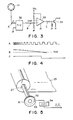
- the image fixing apparatus comprises a heat generating member 21 functioning as a heating member.
- the heat generating member 21 includes a base member made of electrically insulating and heat-resistive material such as alumina or the like or a compound material containing it, a heat generating layer in the form of a line or a stripe made of Ta2N or the like and a surface protection layer resistive against sliding movement, made of Ta2O5 or the like.
- the bottom surface of the heat generating member 21 is smooth, and the front and rear portions are rounded to permit smooth sliding of a fixing film 23.
- the fixing film 23 is made, for example, of PET treated for heat-resistance having a thickness of approximately 6 microns. It is wound on a film feeding shaft 24. The film is fed out in the direction indicated by an arrow D. The fixing film 23 is contacted to the surface of the heat generating member 21 and is taken up on a film take-up shaft 27 by way of a separating and conveying roller 26 having a large curvature.
- the heat generating layer 28 of the heat generating member 21 has a small thermal capacity, and is pulsewisely energized, and it is instantaneously heated up to approximately 300 °C each time.
- the leading and trailing edges of the recording sheet P on which the unfixed toner image is formed are detected by a recording sheet detecting lever 25 and a recording sheet detecting sensor 29.
- the heat generating layer 28 is energized upon necessity.
- the energization of the heat generating member 21 may be controlled in accordance with position detection of the recording sheet P using a sheet feed sensor of an image forming apparatus with which the image fixing apparatus is used.
- the back-up roller 22 includes a core made of metal or the like and an elastic layer made of silicone rubber or the like. It is driven by an unshown driving source and is pressed to the heat generating member 21 through the fixing film 23 moving at the same speed as the recording sheet P advanced by a conveyance guide 10 and having the unfixed toner image T.
- the conveyance speed by the pressing roller 22 is preferably substantially the same as the conveyance speed of the sheet during the unfixed toner image formation on the recording sheet.
- the fixing film 23 speed is determined following this speed.
- Designated by a reference 30 is a sensor for sensing the fixing film 23.
- the temperature of the heat generating layer 28 is instantaneously raised, and therefore, preliminary heating is not required, and the heat transfer to the back-up roller 22 during the non-image-fixing operation is small.
- the fixing film 23 and the toner image T and the recording sheet P are interposed between the heat generating layer 28 and the pressing roller 22, and in addition, the heat generating period is short with the result of steep temperature gradient, by which the back-up roller 22 is not easily raised in temperature. The temperature is maintained lower than the fusing point of the toner even when the image forming operation is continuously performed in a practical manner.
- the toner image T made of heat-fusible toner on the recording sheet P is first heated and fused by the heat generating member 21 through the fixing film, and particularly, the surface portion thereof is heated up to highly above the fusing point, by which the toner is completely softened and fused.
- the back-up roller 23 establishes close contact between the heat generating member 21, the fixing film 23, the toner image T and the recording sheet P, so that the heat transfer is efficient.
- the heat generation of the heat generating member 21 stops, and the recording sheet P is continued to advance and is separated from the heat generating member 21, by which the heat of the toner image T is irradiated so that the toner image T is cooled and solidified.
- the fixing film 23 is separated from the recording sheet P by the separating and conveying roller 26 having a large curvature.
- the temperature of the back-up roller 22 is maintained lower than the fusing point of the toner, and therefore, the heat radiation of the toner image T is promoted.
- the toner image T is once completely softened and fused, and then is solidified, the coagulation force of the toner is very strong, and therefore, the toner behaves as a mass.
- the toner is pressed by the back-up or pressing roller 22 when it is softened and fused by heat, at least a part of the toner image T soaks into the surface layer of the recording sheet P, and then cooled and solidified. This permits the toner image T to be fixed on the recording sheet P without off-set to the fixing film 23.
- the toner fusing point used here means the minimum temperature required for fixing the toner and covers the case where the viscosity thereof decreases to such an extent as can be said to be fused, at the minimum fixable temperature and the case where the viscosity decreases to such an extent as can be said to be softened, at the minimum fixable temperature. Therefore, even when it is said that the toner is fused for convenience, it actually may mean the viscosity decrease to such an extent that it is actually softened. Similarly, when it is said that the toner is cooled and solidified for convenience, it actually may not be solidified depending on the materials of the toner, but can be said that the viscosity is sufficiently increased.
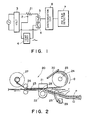
- FIG. 1 there is shown a block diagram further illustrating this embodiment.
- the system of Figure 1 comprises the heat generating member 21, a temperature sensor 2 and a power source 3 for supplying electric power to the heat generating member 1, a temperature controlling circuit 4 for controlling the temperature of the heat generating member 1 by operating a second switch 6.
- a first switch 5 is normally closed.
- An image fixing film stoppage discriminating circuit 8 receives a signal from an image fixing film stoppage detecting means 7 to discriminate stoppage of the fixing film 23. Upon the discrimination, the stoppage discriminating circuit 8 instructs the first switch 5 to open, thus stopping the power supply to the heat generating member 21.
- Figure 5 shows the film stoppage detecting means. As described in conjunction with Figure 2, the fixing film 23 is taken up on the take-up shaft 27. Using this, as shown in Figure 5, the rotation of the film take-up shaft 27 is detected by the film stoppage detecting means.
- a disk 51 is mounted on the take-up shaft 27 rotatable together with movement of the film and is provided with light-transmitting slits.
- a light emitting element 52 and a light receiving element 53 are disposed with the disk 51 therebetween.
- the light receiving signal by the light receiving element 53 is converged to an electric signal by an electric signal converting circuit 54.
- Figure 3 shows the film stoppage discriminating circuit, wherein the pulse output of the film stoppage detecting means 31 is supplied to f-V converter 32 to produce a voltage output.
- a voltage comparator 33 compares the output voltage of the f-V converter 32 and a reference voltage Vref. In accordance with the result of comparison, the first switch 5 of Figure 1 is operated.
- a transistor 34 functions to operate the switch 5.
- the fixing film stoppage detecting means 31 produces pulses at intervals.
- the output voltage of the f-V converter 32 is higher than the reference voltage Vref, so that the transistor 34 is rendered on to close the first switch 5 which may be in the form of a relaying circuit or a contactless switching circuit such as FET.
- the output frequency of the fixing film stoppage detecting means 31 also decreases with the result of reduced output voltage of the f-V converter 32.
- the transistor 34 is rendered off to open the first switch 5 and open the power supply circuit, thus shuting off the power supply thereto.
- the transistor 34 is rendered off when the fixing film is stopped, and therefore, the first switch 5 is opened, and the power supply circuit is opened.
- the film moving speed decreases down to a predetermined, more particularly, when the fixing film stops, the power supply to the heat generating member is stopped, by which the fixing film is locally heated, so that the fixing film is protected from the thermal damage.
- the recording material such as the recording sheet is contacted to the fixing film, the recording material is prevented from over heating.
- the fixing film 23 is provided with a mark 61 at an end thereof.
- the mark 62 is read by a film end reading means 62, by which the film stoppage is detected.
- the film stoppage can be detected with certain detection.
- stoppage of the power supply for stopping the power supply to the heat generating member in accordance with the film stoppage detecting means is the same as in the first embodiment.
- Figure 7 shows a system according to a third embodiment of the present invention in this embodiment, as constructed to the first and second embodiment, the output signal of the fixing film stoppage detecting means 7 or the fixing film stoppage discriminating circuit is supplied to a temperature controlling circuit 4 to stop an output signal of the temperature controlling circuit 4, by which the power supply to the heat generating member 21 is stopped. This eliminates necessity of an independent power supply stopping means.
- the power supply to the heater element can be stopped when the film is stopped, or the film moving speed decreases down to a predetermined due to jammed recording material or the like. Therefore, the film is prevented from being locally heated to an extremely high temperature. Thus, the damage or fusing of the film can be prevented, and in addition, the smoking of the recording material is prevented.
- the copying apparatus comprises a housing 100, a reciprocable original supporting platen 71 made of transparent material such as glass disposed in a top plate 100a of the housing, the original supporting platen is movable above the top plate 100a in the right and left directions a and a ′.
- An original G is placed face-down on the original supporting platen 71 at a predetermined index on the top surface thereof, and the original G is covered by an original cover 1a.
- a slit opening 100b is formed in the top plate 100a, extending perpendicular to the reciprocal movement direction of the original supporting plate 71 (perpendicular to the sheet of drawing).
- the bottom surface that is, the image carrying surface of the original G placed face-down on the original supporting platen 71 is moved in the direction a , by which each part of the original is passed by the slit opening 100b.
- the original is illuminated by light L from a lamp 77 through the slit opening 100b and the transparent original supporting platen 71, so that the original is optically scanned.
- the light reflected by the original is imaged on a surface of a photosensitive drum 73 by an array 72 of short focus and small diameter imaging elements.
- the photosensitive drum 73 has a photosensitive layer such as zinc oxide photosensitive member or an organic photosensitive layer and is rotated in a direction indicated by an arrow b at a predetermined speed about a central shaft 73a. During the rotation, it is uniformly charged to a positive or negative polarity by a charger 74 and is exposed to the imaged light through the slit, so that an electrostatic latent image is sequentially formed corresponding to the image of the original.
- a photosensitive layer such as zinc oxide photosensitive member or an organic photosensitive layer
- the electrostatic latent image is developed into a visualized image with toner made of resin which is softened or fused by heat in a developing device 5.
- the toner image is advanced into an image transfer station containing an image transfer discharger 78.
- the recording material in the form of a transfer sheet of paper P in this embodiment S is contained in a cassette.
- the transfer sheet is singled out of the cassette by rotation of a pick-up roller 76.
- the sheet is then advanced by a registration roller 79 at such timing that when a leading edge of the toner image formed area on the drum 73 reaches the position of the transfer discharger 78, the leading edge of the transfer sheet P reaches a position between the transfer discharger 78 and the photosensitive drum 73, by which they are aligned.
- the toner image on the photosensitive drum 73 is transferred sequentially to the surface of the fed sheet by the transfer discharger 78.
- the sheet now having the toner image transferred thereonto at the transfer station is sequentially separated from the surface of the photosensitive drum 73 by an unshown separating means and is advanced into an image fixing device 11 where the unfixed toner image is heated and fixed.
- the sheet is then, discharged onto a discharge tray 12 outside the image forming apparatus as a print or copy.
- the surface of the photosensitive drum 3 after the toner image transfer is cleaned by the cleaning device 13, by which the contaminations such as the residual toner or the like is removed to be prepared for the next image forming operation.
- the image fixing apparatus comprises an image fixing film 84 in the form of an endless belt, a left side driving roller 85, a right side follower roller 86, a separating roller 26 disposed below the driving roller 85 and a low thermal capacity heater 80 disposed below a position between the driving roller 85 and the follower roller 86.
- the endless fixing film 84 is stretched around these rollers and the heater 80.
- the follower roller 86 functions also as a tension roller for applying tension to the endless fixing film 84.
- the predetermined speed is substantially the conveying speed of the transfer sheet P conveyed from the image forming station 8 of the image forming apparatus and carrying on its top surface the unfixed toner image Ta.
- the fixing apparatus further comprises a pressing or back-up member or roller 22 having a rubber elastic layer made of silicone rubber having a good parting property.
- the back-up roller 22 is pressed to the bottom surface of the heating member 20 under a total pressure of 4 - 7 kg by an unshown urging means through the endless fixing film 24 at its bottom side travel.
- the back-up roller 22 rotates in the counterclockwise direction to peripherally move codirectionally with the conveyance of the transfer sheet P.
- the endless fixing film 84 rotates along an endless path to be repeatedly used for heating and fixing the toner images, it exhibits good heat-resistance, releasing or parting property and durability.
- the thickness thereof is not more than 100 microns, further preferably not more than 50 microns.
- It may be a single layer film of a heat resistive resin such as polyimide, polyetherimide or PFA resin (copolymer of tetrafluoroethylene-perfluoroalkyd vinylether, or it may be a multi-layer film including a thicker film of 20 microns coated with a parting layer of 10 microns at least on the side contactable to the image, the coating being made of PTFE resin (tetrafluoroethylene resin) added by electrically conductive material.
- a heat resistive resin such as polyimide, polyetherimide or PFA resin (copolymer of tetrafluoroethylene-perfluoroalkyd vinylether, or it may be a multi-layer film including a thicker film of 20 microns coated with a parting layer of 10 microns at least on the side contactable to the image, the coating being made of PTFE resin (tetrafluoroethylene resin) added by electrically conductive material.
- PTFE resin tetraflu
- the heater has a low thermal capacity and is in the form of a line or stripe. It, for example, comprises an alumina base plate 821 having a thickness of 1.0 mm, a width of 10 mm and a length of 240 mm and electric resistance material such as Ta2N extending along a length of the base plate 821 substantially at the middle of the width thereof on its bottom surface.
- the electric resistance material is applied thereon with the width of 1.0 mm in the form of a line or a stripe to constitute the heat generating member 22.
- the linear or stripe heat generating member 822 is energized by wiring at its longitudinal opposite ends to produce the heat over the entire length of the heat generating member 822.
- the power supply is in the form of a pulse wave of DC 100 V and the period of 20 msec.
- the power supply controlling circuit controls the pulse width in accordance with the temperature detected by the temperature detecting thermister 823 press-contacted to the back side of the base plate, the target temperature and the energy radiation.
- the pulse width is controlled within the range between 0.5 - 5 msec.
- the heat generating member 822 is instantaneously heated up to a temperature between 200 - 300 °C each time the pulse is produced.
- the temperature of the heater constituted by the base plate 821 and the heat generating member 822 is detected by the thermister 823, and the detected temperature is transmitted to a control circuit 830 ( Figure 12).
- the power supply circuit 831 for supplying power to the heat generating member 822 is controlled, by which the temperature of the heater is controlled at 200 °C.
- the fixing film 84 is not limited to the form of the endless belt. It may be, as shown in Figures 2 and 10, in the form of a film rolled on a feeding shaft 24 and a take-up shaft 27 and stretched therebetween and between the heater 80 and the back-up roller 22 below the separating roller 26.
- the fixing film 23 in this case is advanced from the feeding shaft 24 to the take-up shaft 27 at the same speed as the speed of the transfer sheet P.
- the image forming apparatus operates to produce and introduce to the fixing device 11 from the transfer station 78 a transfer sheet P carrying on its top surface the unfixed toner image Ta.
- a sheet sensor 92 Figures 9 and 10 disposed adjacent to the fixing apparatus
- the power supply to the heat generating member 822 is started at the point of time t2 which is 0.5 sec, in this embodiment, after a delay period (timer period) from the point of time t1 ( Figure 13) at which the film travel starts.
- the heater is energized and is temperature-controlled.
- the transfer sheet P is guided along a guide 89 and is introduced into between the fixing film 84 and the pressing roller 22 in the nip N formed between the heating member 80 and the back-up roller 22.
- the transfer sheet P is moved while its surface carrying the unfixed toner image is being in press-contact with the bottom surface of the fixing film 84 which is moving in the same direction as and at the same speed as the transfer sheet P. It is moved together with the fixing film 84 through the nip N between the heater 80 and the pressing roller 22 without slip or without production of the crease.
- the toner image is heated and softened or fused.
- the heater 80 has a linear heat generating element 822 and a heating member 821 integral with the low thermal capacity heat generating element 822 which is pulsewisely energized to produce pulsewise heat.
- the toner image Ta on the sheet P conveyed at the predetermined conveying speed is introduced together with the fixing film 84 into an effective heating width W determined in accordance with the linear heat generating element 822 of the heater 80, by which it is heated and softened or fused into a fused image Tb.
- This conveying step is used as a cooling step wherein the heat of the softened or fused toner Tb is irradiated, by which the toner is cooled and solidified into a solidified toner image Tc.
- the fixing film 84 When it reaches the separating roller 26, the fixing film 84 is deflected away from the surface of the sheet P along the surface of the separating roller 26 having a large curvature, by which the fixing film 84 and the sheet P are separated, and the sheet P is discharged onto the discharging tray 12.
- the toner is sufficiently cooled and solidified so that the toner is adhered or fixed on the sheet with sufficient force, whereas the contacting force thereof to the fixing film 84 is extremely small, and therefore, the fixing film 84 and the sheet P are separated practically without toner offset to the fixing film 84.
- the linear sheet generating element 822 of the heater 80 is instantaneously heated by the power supply up to a sufficiently high temperature in consideration of the toner fusing point or the fixable temperature, and therefore, the preliminary heating of the heater is not required.
- the heat transfer to the back-up roller 22 is small when the fixing operation is not performed.
- the fixing film, the toner image and the sheet are present between the heater 80 and the back-up roller 22, and a steep temperature gradient is produced due to the short heating period, and therefore, the back-up roller 22 is not heated much, so that the temperature thereof is maintained lower than the toner fusing temperature even if the image forming operation is continuously performed in a practical manner.
- the toner image of the heat-fusible toner on the sheet P is first heated and fused by the heater 80 through the fixing film 84, by which particularly, the surface portion thereof is completely softened or fused.
- the heater, the fixing film, the toner image and the sheet are sufficiently closely contacted by the back-up roller 22, and therefore, the heat transfer therebetween is efficient.
- the toner image itself can be efficiently heated and fused with minimum heating of the sheet P itself.
- the energy consumption can be reduced.
- the size of the heater may be small, so that the thermal capacity thereof is small with the result of unnecessity of the preliminary heating of the heater, by which the power consumption when the image forming operation is not performed can be reduced, and in addition, the temperature rise in the apparatus can be prevented.
- the temperature of the back-up roller 22 is maintained at a temperature lower than the fusing point of the toner, as described in the foregoing, it is possible that the heat radiation of the toner image during the subsequent cooling step can be promoted. This permits shorter cooling period, so that the size of the apparatus can be reduced.
- the image fixing operation is started with the driving (rotation or traveling) of the fixing film 84, and then, the heater 80 is energized to fix the image.
- the energy supply to the heater is first stopped, and then, the movement of the fixing film is stopped. Therefore, during the heat generation, the fixing film is assured to be moved. By this, the fixing film is prevented from locally over heated, by which the film is protected from thermal damage. This improves the durability of the fixing film.
- the drive of the fixing film and the energization of the heating element may be started and stopped simultaneously.
- the drive stop t4 (t a ) of the fixing film after the stoppage of the power supply to the heater at the point of time t3 (A) is effected, provided that the temperature detecting thermister 23 detects that the temperature of the heater is sufficient decreased, for example, down to less than 100 °C by the stoppage of the energy supply to the heat generating element.
- the thickness of the fixing film can be reduced substantially irrespective of the durability of the fixing film, so that the power consumption can be reduced.
- the fixing film in this case may be made of a less expensive material such as PET (polyester) film which is treated for heat-durability having a thickness of 12.5 microns or lower, for example.
- the used fixing film taken up on the take-up shaft can be rewound on the feeding shaft, or the take-up shaft and the feeding shaft are interchanged to use the fixing film repeatedly, if the thermal deformation or thermal deterioration of the fixing film is not significant (rewinding and repeatedly using type).
- the fixing film is preferably made of a material exhibiting high heat-resistivity and mechanical strength, such as polyimide resin film having a thickness of 25 microns which is coated with a parting layer made of fluorine resin or the like having good parting property to constitute a multi-layer film.
- a press-contact releasing mechanism is preferably provided to automatically release the press-contact between the heater and the pressing roller during the rewinding operation.
- a felt pad may be provided to clean the film surface and to apply a slight amount of parting agent such as silicone oil by impregnating the pad with the oil, by which the surface of the film is maintained clean and maintained in good parting property.
- parting agent such as silicone oil
- the fixing film is treated with insulating fluorine resin, electric charge is easily produced on the film, the electric charge disturbing the toner image.
- the fixing film may be rubbed with a discharging brush which is electrically grounded to discharge the film.
- the film may be electrically charged by applying a bias voltage to such a brush without grounding as long as the toner image is not disturbed. It is a possible measure against the image disturbance due to the electric charge to add carbon black or the like in the fixing film. The same means is applicable against the electric charge of the back-up roller.
- anti-electrification agent may be applied or added.
- the structure of the heater 80 and the energization control of the heat generating element 822 are not limited to those described in the foregoing.
- the heating member 80 may be in the form of a heating roller, and the heat generating element 822 may be a thick film resistor or a ceramic chip array having PTC characteristics.
- the energization control is not limited to the pulsewise energization, but it may be in the form of an ordinary AC energization.
- cooling and solidification of the toner may be based on the spontaneous heat irradiation, or may utilize a fan or a heat radiating fins or in another forced cooling type.
- the recording material (transfer material sheet) P is separated from the fixing film 94 immediately after the toner is heated to a sufficiently high temperature and fused in the heating step (in the fixing nip), as shown in Figure 14.
- an image transfer type electrophotographic copying apparatus is taken, but the means and process for the image formation is not limited to this type. It may be of a type wherein a toner image is directly formed and carried on an electrofax sheet or an electrostatic recording sheet or the like, wherein the image is formed and recorded magnetically, or wherein an image is formed with a heat-fusible toner on a recording medium by another image forming process and means.
- An examples of such apparatus are heat-fixing type copying machine, laser beam printer, facsimile machines, microfilm reader-printer, display device and recording device.
- the fixing film is prevented from being locally heated to such an extent that it is thermally damaged at the times when the fixing operation is started and stopped. Therefore, the durability of the fixing film is improved.
- An image fixing apparatus includes a heater which is fixed during an image fixing operation, a film for sliding movement of the heater, wherein a toner image on a recording material is heated by heat from the heater through the film, detecting means for detecting non-movement of the film, and power supply stopping means for stopping energization of the heater in response to an output of the detecting means.
Landscapes
- Physics & Mathematics (AREA)
- General Physics & Mathematics (AREA)
- Fixing For Electrophotography (AREA)
Applications Claiming Priority (4)
| Application Number | Priority Date | Filing Date | Title |
|---|---|---|---|
| JP63234267A JP2510252B2 (ja) | 1988-09-19 | 1988-09-19 | 加熱定着装置 |
| JP234267/88 | 1988-09-19 | ||
| JP63318096A JPH087509B2 (ja) | 1988-12-16 | 1988-12-16 | 定着装置 |
| JP318096/88 | 1988-12-16 |
Publications (3)
| Publication Number | Publication Date |
|---|---|
| EP0363686A2 true EP0363686A2 (de) | 1990-04-18 |
| EP0363686A3 EP0363686A3 (en) | 1990-05-16 |
| EP0363686B1 EP0363686B1 (de) | 1994-11-30 |
Family
ID=26531461
Family Applications (1)
| Application Number | Title | Priority Date | Filing Date |
|---|---|---|---|
| EP89117298A Expired - Lifetime EP0363686B1 (de) | 1988-09-19 | 1989-09-19 | Bildfixiergerät |
Country Status (3)
| Country | Link |
|---|---|
| US (1) | US5043763A (de) |
| EP (1) | EP0363686B1 (de) |
| DE (1) | DE68919639T2 (de) |
Cited By (10)
| Publication number | Priority date | Publication date | Assignee | Title |
|---|---|---|---|---|
| WO1991003771A1 (en) * | 1989-09-11 | 1991-03-21 | Eastman Kodak Company | Toner fixing method and apparatus and image bearing receiving sheet |
| EP0362791A3 (de) * | 1988-10-03 | 1991-05-02 | Canon Kabushiki Kaisha | Bilderzeugungsgerät |
| EP0488357A3 (en) * | 1990-11-30 | 1993-04-14 | Canon Kabushiki Kaisha | Image heating apparatus for heating image through film |
| US5293537A (en) * | 1991-01-10 | 1994-03-08 | Delphax Systems | Image transport fusing system |
| US5294958A (en) * | 1990-01-23 | 1994-03-15 | Oki Electric Industry Co., Ltd. | Image forming apparatus having photoconductor drum and fuser independently operable in timing |
| EP0629930A3 (de) * | 1993-06-18 | 1995-09-06 | Xeikon Nv | Elektrostatographisches Druckgerät mit Bildfixierstation. |
| US5526108A (en) * | 1993-06-18 | 1996-06-11 | Xeikon Nv | Electrostatographic printer with image-fixing station |
| FR2740568A1 (fr) * | 1995-11-01 | 1997-04-30 | Canon Kk | Appareil de formation d'images |
| WO1997015870A1 (de) * | 1995-10-25 | 1997-05-01 | Oce Printing Systems Gmbh | Einrichtung zum überwachen des betriebs einer fixierstation eines elektrographischen druckers |
| WO2001031405A1 (en) * | 1999-10-26 | 2001-05-03 | Matsushita Electric Industrial Co., Ltd. | Image heating device and image forming device |
Families Citing this family (36)
| Publication number | Priority date | Publication date | Assignee | Title |
|---|---|---|---|---|
| US5300997A (en) * | 1987-06-16 | 1994-04-05 | Canon Kabushiki Kaisha | Image fixing apparatus |
| EP0295901B1 (de) * | 1987-06-16 | 1995-12-20 | Canon Kabushiki Kaisha | Bildfixiergerät |
| US5171969A (en) * | 1989-10-30 | 1992-12-15 | Canon Kabushiki Kaisha | Movable film fixing device with heater control responsive to selected sheet size |
| JPH0810379B2 (ja) * | 1989-10-31 | 1996-01-31 | キヤノン株式会社 | 定着装置 |
| US5118920A (en) * | 1989-12-11 | 1992-06-02 | Canon Kabushiki Kaisha | Image fixing apparatus |
| JP2789753B2 (ja) * | 1990-01-09 | 1998-08-20 | キヤノン株式会社 | 定着装置 |
| EP0437204B1 (de) * | 1990-01-11 | 1994-09-14 | Canon Kabushiki Kaisha | Regelung für die seitliche Verschiebung eines Endlosbandes und Fixiergerät mit solcher Regelung |
| DE69118407T2 (de) * | 1990-01-11 | 1996-09-12 | Canon Kk | Vorrichtung zum Steuern der Seitenverschiebung eines Endlos-Bandes und damit ausgestattetes Fixiergerät |
| EP0437205B1 (de) * | 1990-01-12 | 1996-04-03 | Canon Kabushiki Kaisha | Bildfixiergerät |
| JPH03233586A (ja) * | 1990-02-09 | 1991-10-17 | Canon Inc | 定着装置 |
| EP0443799B1 (de) * | 1990-02-20 | 1995-08-16 | Canon Kabushiki Kaisha | Bild-Heizgerät mit von einem rotierenden Element angetriebenen Film |
| EP0443806B1 (de) * | 1990-02-20 | 1996-07-31 | Canon Kabushiki Kaisha | Bilderzeugungsgerät mit Fehlererkennungsdetektor für die Fixiermittel |
| JP2821226B2 (ja) * | 1990-03-13 | 1998-11-05 | キヤノン株式会社 | 加熱装置 |
| US5148226A (en) * | 1990-06-11 | 1992-09-15 | Canon Kabushiki Kaisha | Heating apparatus using endless film |
| EP0461595B1 (de) * | 1990-06-11 | 1996-03-13 | Canon Kabushiki Kaisha | Heizgerät mit Endlosfilm |
| US5291256A (en) * | 1990-11-02 | 1994-03-01 | Canon Kabushiki Kaisha | Image forming apparatus having opening mechanism for jam clearance |
| JP2941962B2 (ja) * | 1991-01-08 | 1999-08-30 | キヤノン株式会社 | 定着装置 |
| JPH05119557A (ja) * | 1991-04-17 | 1993-05-18 | Canon Inc | 画像形成装置 |
| DE69217436T2 (de) * | 1991-09-24 | 1997-07-10 | Canon Kk | Bildheizgerät mit mehreren Temperaturdetektoren |
| JP3055304B2 (ja) * | 1992-04-10 | 2000-06-26 | キヤノン株式会社 | 像加熱装置 |
| JPH05338843A (ja) * | 1992-06-05 | 1993-12-21 | Canon Inc | 定着装置 |
| JP3234660B2 (ja) * | 1992-12-04 | 2001-12-04 | キヤノン株式会社 | 画像形成装置 |
| JPH07234596A (ja) * | 1994-02-21 | 1995-09-05 | Canon Inc | 像加熱装置 |
| JP3513283B2 (ja) * | 1995-09-28 | 2004-03-31 | キヤノン株式会社 | 画像形成装置 |
| JPH10240047A (ja) * | 1997-02-21 | 1998-09-11 | Canon Inc | 画像形成装置 |
| JP4011895B2 (ja) | 2001-11-22 | 2007-11-21 | キヤノン株式会社 | 画像形成装置 |
| JP4058335B2 (ja) * | 2002-12-24 | 2008-03-05 | キヤノン株式会社 | 画像読取記録装置 |
| JP4194536B2 (ja) * | 2004-06-23 | 2008-12-10 | キヤノン株式会社 | 画像処理装置 |
| JP4444876B2 (ja) * | 2005-04-28 | 2010-03-31 | キヤノン株式会社 | 画像読取記録装置 |
| US11803139B2 (en) | 2013-02-18 | 2023-10-31 | Canon Kabushiki Kaisha | Image forming apparatus |
| US9280101B2 (en) | 2013-02-18 | 2016-03-08 | Canon Kabushiki Kaisha | Image forming apparatus with lower and upper guide members |
| JP6476620B2 (ja) * | 2013-08-26 | 2019-03-06 | 株式会社リコー | 定着装置及び画像形成装置 |
| US9969192B2 (en) | 2014-11-19 | 2018-05-15 | Canon Kabushiki Kaisha | Printing apparatus and sheet winding method |
| US9592683B2 (en) | 2014-11-19 | 2017-03-14 | Canon Kabushiki Kaisha | Sheet supplying apparatus and printing apparatus |
| JP6452400B2 (ja) | 2014-11-19 | 2019-01-16 | キヤノン株式会社 | プリント装置 |
| US10399805B2 (en) | 2015-01-09 | 2019-09-03 | Canon Kabushiki Kaisha | Sheet conveyance apparatus |
Family Cites Families (14)
| Publication number | Priority date | Publication date | Assignee | Title |
|---|---|---|---|---|
| US3811828A (en) * | 1970-10-29 | 1974-05-21 | Ricoh Kk | Process and device for heating and fixing an image upon a recording medium |
| US3948215A (en) * | 1972-03-14 | 1976-04-06 | Ricoh Co., Ltd. | Fixing toner images in electrophotography |
| US3809475A (en) * | 1972-12-06 | 1974-05-07 | Xerox Corp | Copier fuser protector |
| JPS5737160Y2 (de) * | 1973-12-21 | 1982-08-16 | ||
| JPS5136952A (de) * | 1974-09-05 | 1976-03-29 | Ricoh Kk | |
| US3924945A (en) * | 1974-12-03 | 1975-12-09 | Xerox Corp | Apparatus for inductive imaging with simultaneous polar ink development |
| DE3109164A1 (de) * | 1981-03-11 | 1982-09-30 | Hoechst Ag, 6000 Frankfurt | Fixiervorrichtung |
| DE3317418A1 (de) * | 1983-05-13 | 1984-11-15 | Hoechst Ag, 6230 Frankfurt | Fixiervorrichtung |
| US4521095A (en) * | 1983-09-02 | 1985-06-04 | Ricoh Company, Ltd. | Electrophotographic copying apparatus including specific toner fusing roll and its method of use |
| US4669852A (en) * | 1983-09-27 | 1987-06-02 | Canon Kabushiki Kaisha | Developing apparatus |
| JPS61162073A (ja) * | 1985-01-10 | 1986-07-22 | Canon Inc | 画像形成装置 |
| JPS6356662A (ja) * | 1986-08-28 | 1988-03-11 | Ricoh Co Ltd | 定着方法 |
| FR2612654B1 (fr) * | 1987-03-19 | 1989-06-23 | Inter Color | Dispositif de marquage au dos d'epreuves photographiques |
| EP0295901B1 (de) * | 1987-06-16 | 1995-12-20 | Canon Kabushiki Kaisha | Bildfixiergerät |
-
1989
- 1989-09-19 US US07/409,341 patent/US5043763A/en not_active Expired - Lifetime
- 1989-09-19 DE DE68919639T patent/DE68919639T2/de not_active Expired - Lifetime
- 1989-09-19 EP EP89117298A patent/EP0363686B1/de not_active Expired - Lifetime
Cited By (19)
| Publication number | Priority date | Publication date | Assignee | Title |
|---|---|---|---|---|
| EP0362791A3 (de) * | 1988-10-03 | 1991-05-02 | Canon Kabushiki Kaisha | Bilderzeugungsgerät |
| WO1991003771A1 (en) * | 1989-09-11 | 1991-03-21 | Eastman Kodak Company | Toner fixing method and apparatus and image bearing receiving sheet |
| US5516394A (en) * | 1989-09-11 | 1996-05-14 | Eastman Kodak Company | Toner fixing method and receiving sheet |
| US5294958A (en) * | 1990-01-23 | 1994-03-15 | Oki Electric Industry Co., Ltd. | Image forming apparatus having photoconductor drum and fuser independently operable in timing |
| EP0488357A3 (en) * | 1990-11-30 | 1993-04-14 | Canon Kabushiki Kaisha | Image heating apparatus for heating image through film |
| US5293537A (en) * | 1991-01-10 | 1994-03-08 | Delphax Systems | Image transport fusing system |
| EP0629930A3 (de) * | 1993-06-18 | 1995-09-06 | Xeikon Nv | Elektrostatographisches Druckgerät mit Bildfixierstation. |
| US5526108A (en) * | 1993-06-18 | 1996-06-11 | Xeikon Nv | Electrostatographic printer with image-fixing station |
| US5978613A (en) * | 1995-10-25 | 1999-11-02 | Oce Printing Systems Gmbh | Device for monitoring the operation of a fixing station of an electrographic printing device |
| WO1997015870A1 (de) * | 1995-10-25 | 1997-05-01 | Oce Printing Systems Gmbh | Einrichtung zum überwachen des betriebs einer fixierstation eines elektrographischen druckers |
| EP0772095A1 (de) * | 1995-11-01 | 1997-05-07 | Canon Kabushiki Kaisha | Bilderzeugungsgerät |
| US5819149A (en) * | 1995-11-01 | 1998-10-06 | Canon Kabushiki Kaisha | Image forming apparatus preventing change of size of image |
| FR2740568A1 (fr) * | 1995-11-01 | 1997-04-30 | Canon Kk | Appareil de formation d'images |
| WO2001031405A1 (en) * | 1999-10-26 | 2001-05-03 | Matsushita Electric Industrial Co., Ltd. | Image heating device and image forming device |
| US6725009B1 (en) | 1999-10-26 | 2004-04-20 | Matsushita Electric Industrial Co., Ltd. | Image heating device and image forming apparatus using the same |
| US6845226B2 (en) | 1999-10-26 | 2005-01-18 | Matsushita Electric Industrial Co., Ltd. | Image heating device and image forming apparatus using the same |
| CN1313893C (zh) * | 1999-10-26 | 2007-05-02 | 松下电器产业株式会社 | 像加热装置及图象形成装置 |
| CN1327302C (zh) * | 1999-10-26 | 2007-07-18 | 松下电器产业株式会社 | 电摄影成像设备中的图像加热定影装置 |
| CN1329779C (zh) * | 1999-10-26 | 2007-08-01 | 松下电器产业株式会社 | 像加热装置及图象形成装置 |
Also Published As
| Publication number | Publication date |
|---|---|
| EP0363686B1 (de) | 1994-11-30 |
| US5043763A (en) | 1991-08-27 |
| DE68919639D1 (de) | 1995-01-12 |
| DE68919639T2 (de) | 1995-05-04 |
| EP0363686A3 (en) | 1990-05-16 |
Similar Documents
| Publication | Publication Date | Title |
|---|---|---|
| EP0363686B1 (de) | Bildfixiergerät | |
| US4998121A (en) | Image forming apparatus | |
| EP0372479B2 (de) | Bildfixiergerät | |
| JP2646444B2 (ja) | 画像加熱定着装置 | |
| EP0432687B1 (de) | Bildfixiergerät | |
| EP0390090B1 (de) | Bildfixiergerät | |
| US5266774A (en) | Set temperature changeable image fixing apparatus | |
| EP0370519B1 (de) | Bildfixiergerät | |
| EP0436955B1 (de) | Bildfixiergerät mit wechselbarem Temperatur-Sollwert | |
| US5171145A (en) | Image fixing apparatus for heat fixing a toner image through a film | |
| EP0369378B1 (de) | Bildfixiergerät | |
| JP2560461B2 (ja) | 定着装置 | |
| JP2511826B2 (ja) | 定着装置 | |
| JP2511825B2 (ja) | 定着装置 | |
| JP2676718B2 (ja) | 定着装置 | |
| JP2694734B2 (ja) | 定着装置 | |
| JPH02143277A (ja) | 画像形成装置 | |
| JPH02113278A (ja) | 画像形成装置 | |
| JP2570838B2 (ja) | 画像加熱定着装置 | |
| JPH0968882A (ja) | 定着装置 | |
| JPH02113279A (ja) | 画像形成装置 | |
| JPH02157881A (ja) | 画像加熱定着装置 | |
| JPH02293771A (ja) | 画像加熱定着装置 | |
| JPH02160272A (ja) | 画像形成装置 | |
| JPH02113280A (ja) | 画像形成装置 |
Legal Events
| Date | Code | Title | Description |
|---|---|---|---|
| PUAI | Public reference made under article 153(3) epc to a published international application that has entered the european phase |
Free format text: ORIGINAL CODE: 0009012 |
|
| PUAL | Search report despatched |
Free format text: ORIGINAL CODE: 0009013 |
|
| 17P | Request for examination filed |
Effective date: 19890919 |
|
| AK | Designated contracting states |
Kind code of ref document: A2 Designated state(s): DE FR GB IT |
|
| AK | Designated contracting states |
Kind code of ref document: A3 Designated state(s): DE FR GB IT |
|
| 17Q | First examination report despatched |
Effective date: 19920525 |
|
| GRAA | (expected) grant |
Free format text: ORIGINAL CODE: 0009210 |
|
| AK | Designated contracting states |
Kind code of ref document: B1 Designated state(s): DE FR GB IT |
|
| REF | Corresponds to: |
Ref document number: 68919639 Country of ref document: DE Date of ref document: 19950112 |
|
| ITF | It: translation for a ep patent filed | ||
| ET | Fr: translation filed | ||
| PLBE | No opposition filed within time limit |
Free format text: ORIGINAL CODE: 0009261 |
|
| STAA | Information on the status of an ep patent application or granted ep patent |
Free format text: STATUS: NO OPPOSITION FILED WITHIN TIME LIMIT |
|
| 26N | No opposition filed | ||
| REG | Reference to a national code |
Ref country code: GB Ref legal event code: IF02 |
|
| PGFP | Annual fee paid to national office [announced via postgrant information from national office to epo] |
Ref country code: GB Payment date: 20070919 Year of fee payment: 19 |
|
| PGFP | Annual fee paid to national office [announced via postgrant information from national office to epo] |
Ref country code: IT Payment date: 20070926 Year of fee payment: 19 |
|
| PGFP | Annual fee paid to national office [announced via postgrant information from national office to epo] |
Ref country code: FR Payment date: 20070914 Year of fee payment: 19 |
|
| PGFP | Annual fee paid to national office [announced via postgrant information from national office to epo] |
Ref country code: DE Payment date: 20080930 Year of fee payment: 20 |
|
| GBPC | Gb: european patent ceased through non-payment of renewal fee |
Effective date: 20080919 |
|
| REG | Reference to a national code |
Ref country code: FR Ref legal event code: ST Effective date: 20090529 |
|
| PG25 | Lapsed in a contracting state [announced via postgrant information from national office to epo] |
Ref country code: IT Free format text: LAPSE BECAUSE OF NON-PAYMENT OF DUE FEES Effective date: 20080919 |
|
| PG25 | Lapsed in a contracting state [announced via postgrant information from national office to epo] |
Ref country code: FR Free format text: LAPSE BECAUSE OF NON-PAYMENT OF DUE FEES Effective date: 20080930 |
|
| PG25 | Lapsed in a contracting state [announced via postgrant information from national office to epo] |
Ref country code: GB Free format text: LAPSE BECAUSE OF NON-PAYMENT OF DUE FEES Effective date: 20080919 |