EP0363722B1 - Méthode et dispositif pour le désempilage de feuilles empilées en blocs sur des palettes - Google Patents
Méthode et dispositif pour le désempilage de feuilles empilées en blocs sur des palettes Download PDFInfo
- Publication number
- EP0363722B1 EP0363722B1 EP89117722A EP89117722A EP0363722B1 EP 0363722 B1 EP0363722 B1 EP 0363722B1 EP 89117722 A EP89117722 A EP 89117722A EP 89117722 A EP89117722 A EP 89117722A EP 0363722 B1 EP0363722 B1 EP 0363722B1
- Authority
- EP
- European Patent Office
- Prior art keywords
- insertion tool
- tool
- blank block
- blank
- tip
- Prior art date
- Legal status (The legal status is an assumption and is not a legal conclusion. Google has not performed a legal analysis and makes no representation as to the accuracy of the status listed.)
- Expired - Lifetime
Links
- 238000000034 method Methods 0.000 title claims description 31
- 238000003780 insertion Methods 0.000 claims description 37
- 230000037431 insertion Effects 0.000 claims description 37
- 238000012545 processing Methods 0.000 claims description 7
- 238000012432 intermediate storage Methods 0.000 claims description 5
- 239000004033 plastic Substances 0.000 claims description 5
- 230000006835 compression Effects 0.000 claims 1
- 238000007906 compression Methods 0.000 claims 1
- 239000011111 cardboard Substances 0.000 description 8
- 235000019504 cigarettes Nutrition 0.000 description 5
- 238000010276 construction Methods 0.000 description 4
- 238000013461 design Methods 0.000 description 4
- 239000000123 paper Substances 0.000 description 4
- 239000011087 paperboard Substances 0.000 description 3
- 230000000284 resting effect Effects 0.000 description 3
- 238000012856 packing Methods 0.000 description 2
- 238000000926 separation method Methods 0.000 description 2
- 238000003860 storage Methods 0.000 description 2
- 241000252254 Catostomidae Species 0.000 description 1
- 238000011161 development Methods 0.000 description 1
- 238000006073 displacement reaction Methods 0.000 description 1
- 230000004886 head movement Effects 0.000 description 1
- 238000004806 packaging method and process Methods 0.000 description 1
- 230000035515 penetration Effects 0.000 description 1
- 238000007493 shaping process Methods 0.000 description 1
Images



Classifications
-
- B—PERFORMING OPERATIONS; TRANSPORTING
- B65—CONVEYING; PACKING; STORING; HANDLING THIN OR FILAMENTARY MATERIAL
- B65H—HANDLING THIN OR FILAMENTARY MATERIAL, e.g. SHEETS, WEBS, CABLES
- B65H3/00—Separating articles from piles
- B65H3/32—Separating articles from piles by elements, e.g. fingers, plates, rollers, inserted or traversed between articles to be separated and remainder of the pile
- B65H3/322—Separating articles from piles by elements, e.g. fingers, plates, rollers, inserted or traversed between articles to be separated and remainder of the pile for separating a part of the pile, i.e. several articles at once
- B65H3/325—Separating articles from piles by elements, e.g. fingers, plates, rollers, inserted or traversed between articles to be separated and remainder of the pile for separating a part of the pile, i.e. several articles at once the pile being pre-marked
-
- B—PERFORMING OPERATIONS; TRANSPORTING
- B65—CONVEYING; PACKING; STORING; HANDLING THIN OR FILAMENTARY MATERIAL
- B65G—TRANSPORT OR STORAGE DEVICES, e.g. CONVEYORS FOR LOADING OR TIPPING, SHOP CONVEYOR SYSTEMS OR PNEUMATIC TUBE CONVEYORS
- B65G61/00—Use of pick-up or transfer devices or of manipulators for stacking or de-stacking articles not otherwise provided for
-
- B—PERFORMING OPERATIONS; TRANSPORTING
- B65—CONVEYING; PACKING; STORING; HANDLING THIN OR FILAMENTARY MATERIAL
- B65H—HANDLING THIN OR FILAMENTARY MATERIAL, e.g. SHEETS, WEBS, CABLES
- B65H2301/00—Handling processes for sheets or webs
- B65H2301/40—Type of handling process
- B65H2301/42—Piling, depiling, handling piles
- B65H2301/422—Handling piles, sets or stacks of articles
- B65H2301/4225—Handling piles, sets or stacks of articles in or on special supports
- B65H2301/42256—Pallets; Skids; Platforms with feet, i.e. handled together with the stack
-
- Y—GENERAL TAGGING OF NEW TECHNOLOGICAL DEVELOPMENTS; GENERAL TAGGING OF CROSS-SECTIONAL TECHNOLOGIES SPANNING OVER SEVERAL SECTIONS OF THE IPC; TECHNICAL SUBJECTS COVERED BY FORMER USPC CROSS-REFERENCE ART COLLECTIONS [XRACs] AND DIGESTS
- Y10—TECHNICAL SUBJECTS COVERED BY FORMER USPC
- Y10S—TECHNICAL SUBJECTS COVERED BY FORMER USPC CROSS-REFERENCE ART COLLECTIONS [XRACs] AND DIGESTS
- Y10S414/00—Material or article handling
- Y10S414/10—Associated with forming or dispersing groups of intersupporting articles, e.g. stacking patterns
- Y10S414/12—Associated with forming or dispersing groups of intersupporting articles, e.g. stacking patterns including means pressing against top or end of group
Definitions
- the invention relates to a method for destacking blanks of paper, cardboard, cardboard, plastic or the like stacked in blocks on pallets, which are then fed as a cutting block to further processing or intermediate storage, the individual cutting blocks being successively at least slightly removed from their respective base by means of a plunging tool are raised and then the respective cutting block is lifted off and transported away.
- the invention further relates to a device for unstacking blanks of paper, cardboard, cardboard, plastic or the like stacked in blocks on pallets, which are then fed as a cutting block for further processing or intermediate storage, with a spatially controlled gripping head on which an approximately horizontally aligned Grooving tool is stored.
- Paper or cardboard blanks are processed in large quantities on many packaging machines, especially cigarette packing machines and folder gluers. Such machines are becoming more and more powerful, so that increases in performance are often only meaningful if the problem of loading these machines with blank stacks can be solved satisfactorily. For this purpose, the cut stacks are to be delivered to the machines on pallets.
- WO-A-86 07579 which corresponds to the preamble of claims 1 and 9, a method for unstacking blanks stacked in blocks on pallets, for example made of paper or cardboard, is known, in which the blanks are subsequently fed as a cutting block for further processing .
- a tool that can be raised and lowered and rotated about a vertical axis is provided, which consists of a vertical support axis rotatable about the vertical axis and a plunging tool attached to its lower end.
- the piercing tool consists of a plurality of rods mounted in horizontal guides of the support arm, each of which is surrounded along its longitudinal extension by a flexible sleeve, which therefore forms a closed loop around the rods, and which is attached to the support arm with both ends.
- the covering of the shell therefore follows the movement of the rod that is enclosed. In this way, the piercing tool can be inserted under or pulled out from under a stack without any frictional forces occurring between the piercing tool and the stack.
- a disadvantage of the known method and the device used here is that no measures are provided to first determine the position of the piercing tool relative to the position of the stack to be handled.
- FR-A 2 563 197 discloses a method for horizontally separating stacks of flat objects using horizontally movable piercing tools.
- the vertically movable grooving tools are designed to be movable along horizontal guides.
- the invention has for its object to develop a method and an apparatus of the type described in such a way that blanks stacked on pallets, such as cigarette pack blanks and folding box blanks of any kind, can be removed as individual blanks without having to use expensive special equipment First determine the position of the plunger relative to the position of the respective stack on the pallet.
- the invention proposes a method in which the tip of the plunging tool, which is at least roughly positioned in a horizontal plane, immediately prior to the plunging process for exact positioning in a vertical direction device on a base protruding from the vertical plunge side of the cutting block before the plunge tool is retracted.
- Normal pads made of paper, cardboard or plastic can be used as a base for the blanks stacked on the pallets in blocks.
- a blank block arranged on the pallet on the outer edge of the entire stack is separated from its base by suction and then a plunge tool is inserted under the bottom blank of the respective blank block, by means of which the respective blank block is then lifted off and transported away.
- This further development of the method is used when there is no underlay protruding from the attack side of the cutting block, which is why this method is only suitable for cutting blocks arranged on the outer edge of the entire stack on the pallet. After removal of one of these blanking blocks, the remaining blanking blocks can be unstacked with the aid of a plunge tool supported on their base.
- a cutting block arranged on the outer edge of the entire stack on the pallet can also be displaced relative to its base by inserting fingers from above into gaps of the cutting block or between adjacent cutting blocks, before a plunging tool is then inserted under the bottom cut of the respective cutting block, through which the respective cutting block is then lifted off and transported away.
- the exact positioning of the plunging tool takes place in the vertical direction by resting the tip of the plunging tool on the respective base and by a slight relative movement of the tip produced thereby relative to the vertical positioning movement of the entire plunging tool.
- the contact force of the tip of the piercing tool on the respective base, which ends the vertical positioning movement of the piercing tool, is variable according to the invention depending on the nature of the base and / or on the position of the cutting block to be removed on the pallet.
- the respective cutting block is transported away by the piercing tool, the cutting block being secured against slipping on the piercing tool by a holding force during this removal.
- the individual cutting blocks are placed by the inserting tool on a conveyor belt designed as an intermediate store, so that on the one hand there are short transport routes between inserting tool and storage and on the other hand no downtime of the downstream machine is required when changing the pallet.
- the invention also proposes a device in which the plunging tool is mounted so that it can be pivoted slightly about a horizontal axis, the pivoting movement of the plunging tool in the lowering direction being limited by a stop and the pivoting movement of the plunging tool in the opposite direction being monitored by a shift lever , which interrupts the lowering movement of the gripping head by means of a switch as soon as the plunging tool has been pivoted by a predeterminable angle against an adjustable spring force.
- This inventive design of the unstacking device enables, with little technical effort, reliable unstacking of blanks stacked in blocks on pallets without the need for special intermediate layers or stacking containers.
- the spring force exerted on the piercing tool opposite to the lowering direction can be adjusted by means of an adjusting element, for example a lifting magnet or pressure medium cylinder.
- an adjusting element for example a lifting magnet or pressure medium cylinder.
- a movable pressure ram is arranged on the gripping head outside the range of movement of the piercing tool.
- a movable holding stamp is arranged on the gripping head within the range of movement of the piercing tool, which secures the respective cutting block against slipping on the piercing tool.
- the piercing tool is arranged on a support plate which is mounted on the gripping head so as to be movable in a horizontal direction.
- the piercing tool is designed either as a tongue-like plate with a central tip or as a forked plate with two tips.
- the tips are preferably slightly bent downward relative to the horizontal plate and each have a defined contact surface, so that reliable underriding of the bottom blank of the respective blanking block is ensured without the risk of damaging the base.
- At least one suction cup is arranged on the gripping head on the side next to the piercing tool.
- piercing fingers can also be arranged on the gripping head on the side next to the piercing tool, which can be moved in the vertical direction relative to the piercing tool, in order to shift cutting blocks arranged on the pallet on the base, in particular on the outer edge of the entire stack, by these piercing fingers are introduced from above into gaps which are either formed by appropriate shaping of the blank in the blanking block or result between adjacent blanking blocks.
- the invention proposes to provide the piercing tool with at least one compressed air duct opening on its front side;
- the compressed air emerging from this compressed air channel facilitates the insertion of the piercing tool between the bottom blank of the respective blanking block and its base and prevents damage in the process.
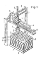
- FIG. 1 shows a pallet P on which a multiplicity of cutting blocks Z are stacked.
- Each blanking block Z consists of a certain number of blanks, for example blanks for cigarette packs or folding boxes.
- a base U in the form of an intermediate layer made of paper or cardboard is arranged between each layer of the cutting blocks Z, by means of which the cutting blocks Z lying one above the other are separated from one another.
- the intermediate layers thus form the respective base U for the individual cutting blocks Z.
- the particular base can be formed, in particular for internal transport, by arranging them on the pallet P in the individual layers Cutting blocks Z in relation to the cutting blocks Z of the adjacent layer are laterally offset or stacked rotated by 90. It is also possible in this way to achieve an exact separation of the cutting blocks Z arranged one above the other len.
- a gripping head 1 which is only shown schematically in FIG. 1, is used to unstack the cutting blocks Z which are stacked in blocks on the pallet P.
- this gripping head 1 is rotatably arranged at the lower end of a guide rod 2, as indicated by the double arrow shown.
- the guide rod 2 is arranged to be movable in the vertical direction on a carriage 3, which in turn can be moved on a horizontal support beam 4.
- This support beam 4 is in turn arranged on a carriage 5 which can be moved on the horizontally extending yoke 6 of a portal 7.
- positioning of the gripping head 1 in the horizontal direction is possible by moving the carriage 5 and the carriage 3, for example using photocells and thus enabling control independent of the respective blank size.
- the height is adjusted by moving the guide rod 2 on the carriage 3.
- the gripping head 1 can be aligned by rotating it relative to the guide rod 2.
- a conveyor belt 8 which runs within the portal 7 and the individual cutting blocks Z either for immediate further processing, for example a cigarette packing machine or a folder gluer, or an interim storage.
- other types of removal of the blanks taken from the pallet P in blocks are also possible.
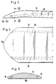
- FIGS. 2 to 6 shows a perspective representation of the spatially controlled movable gripping head 1, on which an approximately horizontally oriented piercing tool 9 is arranged, which is shown in detail in FIGS. 3 to 6.
- the piercing tool 9 is formed by a tongue-like plate 10 with a central tip 10a.
- This tip 10a is bent slightly downwards relative to the horizontally extending plate 10 and is formed with a defined contact surface 10b, so that the piercing tool 9 can be placed specifically on a support U before the plate 10 is moved horizontally relative to the gripping head 1 under each cutting block Z to be removed can be retracted.
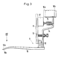
- the tongue-like plate 10 is arranged on a support plate 11 which is mounted on the gripping head 1 such that it can be moved in the horizontal direction, as can be seen in particular from FIG.
- the plate 10 is slightly pivotable relative to the support plate 11 about a bearing pin 12 which forms a horizontal axis.
- the pivoting movement is in the lowering direction of the plate, i.e. 3 in the counterclockwise direction, limited by a stop which is formed by a screw 13 resting on the support plate 11.
- This screw 13 is arranged in a shift lever 14 which is attached to the top of the plate 10 and extends approximately at right angles upwards.
- a tension spring 15 also acts on the shift lever 14, which pulls the screw 13 against the support plate 11 and thus holds the plate 10 in the horizontal, possibly slightly downwardly inclined normal position. Only when the tip 10a of the plate 10 is placed with its support surface 10b on a base U does the plate 10 pivot slightly (clockwise according to FIG. 3) against the force of the tension spring 15. This pivoting movement is monitored by proximity switches 16a, 16b , wherein the proximity switch 16a serves to stop the lowering movement of the gripping head 1 as soon as it has become free, and the proximity switch 16b is used to initiate a slight return movement if the intermediate position between the two proximity switches 16a, 16b has been exceeded.
- one end of the tension spring 15 can be arranged on an adjusting element, for example a lifting magnet 17, according to FIG. 3. by actuating the biasing force of the tension spring 15 is variable.
- the plate 10 can, according to FIGS. 4 to 6, be provided with one or more compressed air channels 18, which are on the front of the plate 10 open and facilitate the piercing process of the plate 10 by the flowing compressed air.
- FIGS. 1 and 2 A denesting process is now to be explained with reference to FIGS. 1 and 2, specifically using blanks for hard cigarette packs.
- the cutting blocks Z stacked on the pallet P are successively lifted from their respective base U by means of the piercing tool 9, for which purpose the gripping head 1 is first positioned at least roughly in a horizontal plane above the pallet P by moving the carriage 3 and the carriage 5 yourself the tip 10a of the plate 10 of the piercing tool 9 is located laterally above the cutting block Z to be removed. Care must be taken to ensure that the tip 10a of the plate 10, upon a subsequent lowering movement of the gripping head 1, reaches the base U, which protrudes from the vertical piercing side of the cutting block Z to be removed, as shown in particular in FIG. 2.
- This protrusion of the base U in relation to the freely accessible side of the cutting block Z results, for example, from the corresponding shape of the cuts. Since the approximately trapezoidal protrusion of the base U is supported at its edges on the cutting block Z underneath, thin intermediate layers, for example made of paper, are sufficient to form the corresponding base U.
- a movable pressure stamp 19 is arranged on the gripping head 1 outside the range of movement of the piercing tool 9. This pressure stamp 19 holds the respective blank stack Z firmly on the base, while the plunging tool in the form of the plate 10 is retracted. In order not to hinder this retraction, the pressure stamp 19 is located outside the range of movement of the plate 10.
- the cutting block Z lifted off the pallet P is then transferred to the conveyor belt 8.
- the pressure stamp 19 can also be extended here in order to hold the respective cutting block Z on the conveyor belt 8 when the plate 10 is pulled back by relative movement of its support plate 11 relative to the gripping head 1 under the cutting block Z, with the holding stamp 20 having of course been lifted off the top of the cutting block Z beforehand.
- the heel movement is usefully interrupted by deflection of the plate 10 relative to the support plate 11 due to signals from the proximity switches 16a and 16b.
- the tip 10a of the plunging tool 9 comprising the plate 10, which is at least roughly positioned in the horizontal plane, is supported immediately before the plunging process for exact positioning in the vertical direction on the base U protruding from the vertical plunge side of the cutting block Z. is before the piercing tool 9 is retracted.
- This support easily results in exact positioning in the vertical direction, the contact force of the tip 10a on the base U being only slight.
- this pivoting movement can be used to end the vertical lowering of the entire gripping head 1 , for example with the help of the construction shown in Fig.3.
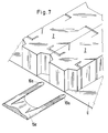
- FIG. 7 shows a modified version of the actual piercing tool 9, which in this example is designed as a forked plate 10c which has two tips 10a. With these two tips 10a, the plate 10c is supported laterally next to a projecting part of the cutting blocks Z on the base U. This indicates that the actual design of the piercing tool 9 can be easily adapted to the respective shape of the blanks without changing the overall concept.
- the gripping head 1 can be provided laterally next to the piercing tool 9 with at least one suction pad 21.
- the cutting block Z arranged on the pallet P on the outer edge of the entire stack is separated from its base U, namely pulled forward, so that the piercing tool 9, for example in the form of a plate 10, is then placed under the lowest section of the respective cutting block Z can be retracted, whereupon the respective cutting block Z is lifted off and transported away.
- a plate 23 can be arranged between the suckers 21, which plate is moved against the cuts and aligns them before the suction process.
- these suction devices 21 can be arranged on the gripping head 1 in addition to the construction elements described above, so that the two methods of denesting described above can alternatively be carried out with the device already explained.
- the Fig.8 shows that even in this modified construction, the gripping head 1 can be provided in this case with paired pressure stamps 19 and a holding stamp 20, in order to prevent the cutting block Z from slipping when pulling forward by means of the suction device 21 and the gripping head movement and when To prevent insertion of the plate 10 and on the other hand to ensure reliable holding of the separated cutting block Z on the piercing tool 9.
- the suction cups 21 are moved out of their working position shown in FIG. 8 when the gripping head works in the manner described above.
- FIG. 9 An alternative embodiment to the construction shown in FIG. 8 is shown in FIG. 9.
- plunge fingers 22 are arranged on the gripping head 1 and can be moved in the vertical direction relative to the plunging tool 9. These piercing fingers 22 can be inserted from above into gaps that are either formed in the actual cutting block Z in accordance with the design of the cuts or that result between adjacent cutting blocks Z.
- the puncturing fingers 22 are shown in dash-dotted lines in FIG. 9 before they are inserted into corresponding gaps between adjacent cutting blocks Z.
- the piercing fingers 22 are then displaced in the horizontal direction with or relative to the gripping head 1, so that the cutting block Z arranged on the edge of the pallet P is advanced over the base U.
- the plate 10 of the piercing tool 9 can now be guided from below under the bottom cut of the slightly advanced cutting block Z in order to grip, separate and remove it.
- printing and holding stamps 19 and 20 are arranged in order to support the separation and removal process.
Landscapes
- Engineering & Computer Science (AREA)
- Mechanical Engineering (AREA)
- Making Paper Articles (AREA)
Claims (19)
caractérisé
en ce que la pointe (10a) de l'outil de plongée (9) positionnée au moins de manière grossière dans un plan horizontal, juste avant l'opération de plongée et en vue d'un positionnement exact dans la direction verticale, s'appuie sur une base de support (U) en saillie par rapport à la surface de plongée verticale du bloc de feuilles découpées (Z), avant que ne soit effectuée la pénétration de l'outil de plongée (9).
en ce que l'outil de plongée (9) est monté de manière à pouvoir pivoter très légèrement autour d'un axe horizontal (12), le mouvement de pivotement de l'outil de plongée (9) étant limité dans la direction de l'abaissement par une butée (13), et le mouvement de pivotement de l'outil de plongée (9) est contrôlé dans la direction opposée, par un levier de commande (14), qui par l'intermédiaire d'un commutateur (16a, 16b), interrompt le mouvement d'abaissement de la tête de préhension (1), dès que l'outil de plongée (9) a été pivoté à l'encontre d'une force élastique réglable, d'un angle pouvant être prédéfini.
Applications Claiming Priority (2)
| Application Number | Priority Date | Filing Date | Title |
|---|---|---|---|
| DE3835032 | 1988-10-14 | ||
| DE3835032A DE3835032A1 (de) | 1988-10-14 | 1988-10-14 | Verfahren und vorrichtung zum entstapeln von blockweise auf paletten gestapelten zuschnitten |
Publications (4)
| Publication Number | Publication Date |
|---|---|
| EP0363722A2 EP0363722A2 (fr) | 1990-04-18 |
| EP0363722A3 EP0363722A3 (fr) | 1991-02-27 |
| EP0363722B1 true EP0363722B1 (fr) | 1993-06-09 |
| EP0363722B2 EP0363722B2 (fr) | 1996-10-30 |
Family
ID=6365131
Family Applications (1)
| Application Number | Title | Priority Date | Filing Date |
|---|---|---|---|
| EP89117722A Expired - Lifetime EP0363722B2 (fr) | 1988-10-14 | 1989-09-26 | Méthode et dispositif pour le désempilage de feuilles empilées en blocs sur des palettes |
Country Status (3)
| Country | Link |
|---|---|
| US (2) | US5040942A (fr) |
| EP (1) | EP0363722B2 (fr) |
| DE (2) | DE3835032A1 (fr) |
Families Citing this family (65)
| Publication number | Priority date | Publication date | Assignee | Title |
|---|---|---|---|---|
| US5139387A (en) * | 1989-09-05 | 1992-08-18 | G.D. S.P.A. | Apparatus for feeding packaging machines with stacks of sheet material |
| DE4001053A1 (de) * | 1990-01-16 | 1991-07-18 | Focke & Co | Vorrichtung zum abheben von (zwischen-)lagen gestapelter gegenstaende |
| DE4124077C2 (de) * | 1991-07-19 | 1995-03-09 | Fraunhofer Ges Forschung | Einrichtung zur Aufnahme von biegeschlaffen flächigen Teilen |
| IT1252449B (it) * | 1991-07-22 | 1995-06-16 | Gd Spa | Procedimento e dispositivo per ordinare pile di sbozzati in una macchina confezionatrice |
| DE9111787U1 (de) * | 1991-09-20 | 1991-11-14 | Niepmann Traylift Transportsysteme GmbH & Co KG, 5820 Gevelsberg | Vorrichtung zum Entstapeln von blockweise auf Paletten gestapelten Zuschnitten |
| DE9111788U1 (de) * | 1991-09-20 | 1991-11-14 | Niepmann Traylift Transportsysteme GmbH & Co KG, 5820 Gevelsberg | Vorrichtung zum Entstapeln von blockweise auf Paletten gestapelten Zuschnitten |
| DE4210592A1 (de) * | 1992-03-31 | 1993-10-07 | Schmermund Maschf Alfred | Hochregallager |
| IT1257810B (it) * | 1992-05-26 | 1996-02-13 | Gd Spa | Metodo per la separazione di due file di pacchetti di sigarette |
| DE4222609A1 (de) * | 1992-07-10 | 1994-01-20 | Focke & Co | Verfahren und Vorrichtung zum Handhaben von Zuschnitt-Stapeln |
| IT1258021B (it) * | 1992-07-28 | 1996-02-20 | Gd Spa | Metodo per il prelievo di pile di sbozzati |
| IT1256310B (it) * | 1992-11-11 | 1995-11-30 | Ocme | Dispositivo per il prelievo,la movimentazione e la deposizione di una pila di fustellati |
| EP0616874B1 (fr) * | 1993-03-24 | 1997-09-10 | Hauni Maschinenbau Aktiengesellschaft | Bras de robot pour robot à portique |
| IT1263434B (it) * | 1993-06-16 | 1996-08-05 | Gd Spa | Unita' di prelievo ed alimentazione di pile di sbozzati |
| DE59501313D1 (de) * | 1994-06-06 | 1998-02-26 | Digitron Ag | Vorrichtung und Verfahren zur Aufnahme von Artikeln |
| DE19500290C2 (de) * | 1994-09-09 | 1997-07-24 | Baumueller Anlagen Systemtech | Verfahren zum Aufeinanderstapeln von mit einer Greifeinrichtung erfaßbaren, nach oben offenen Behältern sowie Greifeinrichtung zum Auf- und Abstapeln von nach oben offenen Behältern |
| IT1281784B1 (it) * | 1995-04-28 | 1998-03-03 | Gd Spa | Dispositivo per il prelievo di pile di prodotti da un supporto |
| DE19518256C2 (de) * | 1995-05-18 | 1998-10-08 | Topack Verpacktech Gmbh | Vorrichtung zum Entstapeln von blockweise und unter Einfügung von flachen Zwischenlagen auf Paletten gestapelten Zuschnitten |
| IT1279959B1 (it) * | 1995-06-22 | 1997-12-23 | Gd Spa | Dispositivo per il prelievo di pile di prodotti da un supporto |
| IT1281245B1 (it) * | 1995-11-15 | 1998-02-17 | Sasib Spa | Dispositivo prelevatore-alimentatore di mazzi di fogli, fustellati, o simili, in particolare nelle macchine impacchettatrici di |
| DE19618344A1 (de) * | 1996-05-08 | 1997-11-13 | Focke & Co | Vorrichtung zum Handhaben von Zuschnittstapeln |
| IT1285719B1 (it) * | 1996-05-24 | 1998-06-18 | Gd Spa | Dispositivo per la formazione ed il trasferimento di pile ordinate di foglietti, in particolare banconote |
| DE19653953A1 (de) | 1996-12-21 | 1998-06-25 | Topack Verpacktech Gmbh | Verfahren und Vorrichtung zum Entpalettieren von Artikeln |
| ES2139431T3 (es) * | 1997-02-25 | 2000-02-01 | Cat System S R L | Aparato para la ubicacion de grupos de productos en paletas. |
| DE19718090A1 (de) * | 1997-04-29 | 1998-11-05 | Promot Ind Automatisierungs Sy | Handhabungssystem für Werkstücke mit Umstapelzelle für Werkstückträger |
| DE19959285B4 (de) * | 1999-12-09 | 2008-01-31 | J. Schmalz Gmbh | Vakuum-Greifsystem zum Greifen eines Objekts und Handhabungsgerät zum Handhaben eines Objekts mit Hilfe eines Vakuum-Greifsystems |
| ITBO20000356A1 (it) * | 2000-06-16 | 2001-12-16 | Gd Spa | Metodo e dispositivo di prelievo di pile di sbozzati . |
| US6887191B2 (en) * | 2000-10-12 | 2005-05-03 | International Paper Company | Carton bottom forming method and apparatus |
| US6746203B2 (en) * | 2001-03-30 | 2004-06-08 | Axium, Inc. | Gripping and transport clamp mounted at the end of a robotic arm and method for operating the same |
| ES2269336T3 (es) * | 2001-06-08 | 2007-04-01 | Bielomatik Leuze Gmbh + Co. Kg | Dispositivo y procedimiento para la subdivision de una pila de hojas en resmas de un numero de hojas predeterminado. |
| ITMO20020050A1 (it) * | 2002-02-28 | 2003-08-28 | Ferrari & Cigarini Srl | Dispositivo per la depalletizzazione di pacchi di piastrelle |
| ITBO20020367A1 (it) * | 2002-06-11 | 2003-12-11 | Gd Spa | Dispositivo di presa per pile di sbozzati |
| EP1378472B1 (fr) * | 2002-07-02 | 2008-03-19 | Müller Martini Holding AG | Dispositif pour transporter une pile de feuilles imprimées, juxtaposées sur chant, reposant sur un support |
| DE10252844A1 (de) * | 2002-11-13 | 2004-06-03 | Alpma Alpenland Maschinenbau Gmbh | Manipulator |
| DE10349021A1 (de) * | 2003-10-13 | 2005-05-12 | Deutsche Post Ag | Verfahren und Anordnung zum Aufnehmen von quaderförmigem Stückgut aus einem Container, von einem LKW-Aufbau oder einem dergleichen einseitig offenen Laderaum und zur Ablage des Stückgutes |
| CN100360384C (zh) * | 2003-10-14 | 2008-01-09 | 云南紫金科贸有限公司 | 一种烟箱实托盘拆垛过程中散盘处理系统 |
| US20050089389A1 (en) * | 2003-10-22 | 2005-04-28 | Saga Automation, Inc. | Method, system, and apparatus for securing a section of a vertical stack of generally flat sheets, cartons, and like |
| DE10355876A1 (de) | 2003-11-25 | 2005-07-28 | Hauni Maschinenbau Ag | Anordnung zum Befüllen und/oder Entleeren von mit Artikeln gefüllten und/oder zu befüllenden Behältern sowie Handhabungsvorrichtung zum Transportieren der Behälter |
| DE102006017379A1 (de) * | 2006-04-11 | 2007-10-18 | Focke & Co.(Gmbh & Co. Kg) | Einrichtung zur Handhabung von Bobinen aus Verpackungsmaterial |
| US20070280812A1 (en) * | 2006-05-17 | 2007-12-06 | Axium Inc. | Tool and method for mixed palletizing/depalletizing |
| US20080112788A1 (en) * | 2006-11-10 | 2008-05-15 | Sage Automation, Inc. | Depalletizing Apparatus and Method |
| JP5144661B2 (ja) * | 2007-08-02 | 2013-02-13 | 平田機工株式会社 | 部品移送装置及び方法 |
| ATE459560T1 (de) * | 2007-09-13 | 2010-03-15 | Multivac Haggenmueller Gmbh | Vorrichtung zur aufnahme und zum transport eines gutes |
| SE0800607L (sv) * | 2008-03-14 | 2009-09-15 | Idab Wamac Internat Ab | Förfarande och anordning för att avlägsna en översta grupp av ytutbredda alster av foldertyp ur en stapel av sådana grupper |
| DE102010018963A1 (de) * | 2010-04-28 | 2011-11-03 | IPR-Intelligente Peripherien für Roboter GmbH | Robotergreifer und Handhabungsroboter |
| DE102011082967B4 (de) | 2011-09-19 | 2020-08-06 | Masterwork Machinery Gmbh | Vorrichtung und Verfahren zum Anheben eines auf einer Unterlage angeordneten Stapels |
| US9126770B1 (en) | 2012-02-09 | 2015-09-08 | Automatan, Inc. | Aligning and stacking palletizing machine |
| SE538951C2 (sv) * | 2014-03-28 | 2017-02-28 | Yaskawa Nordic Ab | gripdon |
| US9498887B1 (en) * | 2014-07-24 | 2016-11-22 | X Development Llc | Two-faced linearly actuated gripper |
| JP6460245B2 (ja) * | 2015-08-27 | 2019-01-30 | 村田機械株式会社 | 取出装置及び保管装置 |
| FR3043078B1 (fr) | 2015-10-30 | 2020-09-18 | C E R M E X Constructions Etudes Et Rech De Materiels Pour Lemballage Dexpedition | Dispositif et methode d'extraction |
| US10569422B2 (en) | 2016-01-20 | 2020-02-25 | Soft Robotics, Inc. | End of arm tools for soft robotic systems |
| RU2639606C1 (ru) * | 2016-10-17 | 2017-12-21 | Акционерное общество "Квантум Системс" | Роботизированный счетно-сортировальный комплекс |
| JP6588513B2 (ja) * | 2017-09-05 | 2019-10-09 | ファナック株式会社 | ワーク取り出し装置 |
| WO2019094964A1 (fr) * | 2017-11-10 | 2019-05-16 | Soft Robotics, Inc. | Éléments de fixation ayant des points de prolifération bactérienne réduits, des capacités d'étanchéité et des caractéristiques de protection de composant |
| US11072080B2 (en) * | 2017-11-10 | 2021-07-27 | Soft Robotics, Inc. | End of arm tools for soft robotic systems |
| CN108639751A (zh) * | 2018-07-10 | 2018-10-12 | 深圳福美信自动化工程有限公司 | 一种吸附装置及多余吸附产品的分离方法 |
| ES2931452T3 (es) | 2018-07-20 | 2022-12-29 | Tgw Logistics Group Gmbh | Procedimiento y almacén de preparación de pedidos para almacenar y preparar mercancías |
| CN109436816A (zh) * | 2019-01-09 | 2019-03-08 | 合肥泰禾光电科技股份有限公司 | 拨动拆垛装置及拨动拆垛方法 |
| DE102019110704B3 (de) * | 2019-04-25 | 2020-05-14 | Stöcklin Logistik Ag | Vorrichtung und Verfahren zum Depalettieren von stapelbaren Stückgutgebinden |
| DE102019115634B3 (de) * | 2019-06-07 | 2020-12-03 | Bystronic Laser Ag | Sortiersystem für eine Werkzeugmaschine, Werkzeugmaschine und Verfahren zum Sortieren von Schnittteilen |
| CN110758901A (zh) * | 2019-10-22 | 2020-02-07 | 天津长荣科技集团股份有限公司 | 铺纸垫板 |
| DE102021117061A1 (de) * | 2021-07-02 | 2023-01-05 | Khs Gmbh | Zuschnittzuführanordnung und Verpackungsmaschine zur Bildung von Verkaufsgebinden |
| US20240227205A9 (en) * | 2022-10-25 | 2024-07-11 | Intelligrated Headquarters, Llc | Logistics robotic system with adjustable multi-zone end effector |
| EP4660110A1 (fr) * | 2024-06-06 | 2025-12-10 | R.A Jones & Co. | Procédé pour décharger une pile de découpes d'un élément de support |
| DE102024130322A1 (de) * | 2024-10-18 | 2026-04-23 | Syntegon Packaging Systems Ag | Produkthandhabungsvorrichtung sowie Verfahren zu einem Handhaben von Stapeln aus Verpackungsrohlingen zu einem Beladen eines Kartonmagazins |
Family Cites Families (10)
| Publication number | Priority date | Publication date | Assignee | Title |
|---|---|---|---|---|
| DE2306691A1 (de) * | 1973-02-10 | 1974-08-15 | Hesser Ag Maschf | Vorrichtung zum entladen von mit gegenstaenden beladenen paletten |
| DD159617A1 (de) * | 1981-06-12 | 1983-03-23 | Wolfgang Jahnke | Vorrichtung zum aufnehmen und handhaben von flachen stapelfaehigen gegenstaenden |
| DE3414996C1 (de) * | 1984-04-19 | 1985-11-14 | Windmöller & Hölscher, 4540 Lengerich | Vorrichtung zum Abschieben von auf einer Trageinrichtung abgelegten Stapeln oder Paketen |
| US4551053A (en) * | 1984-05-29 | 1985-11-05 | Fuji Photo Film Co. Ltd. | Sheet sub-stack separating and feeding apparatus |
| JPH0678150B2 (ja) * | 1984-07-30 | 1994-10-05 | 新王子製紙株式会社 | シ−ト束分離装置 |
| US4789295A (en) * | 1985-02-26 | 1988-12-06 | International Business Machines Corp. | Article manipulator for robot |
| IT8522218V0 (it) * | 1985-06-19 | 1985-06-19 | Ottavio Conterno | Palettizzatore automatico. |
| IT1207662B (it) * | 1987-04-15 | 1989-05-25 | Gd Spa | Apparecchiatura di alimentazione di pile di materiale in foglio ad unamacchina utilizzatrice |
| DE3718601A1 (de) * | 1987-06-03 | 1988-12-22 | Bat Cigarettenfab Gmbh | Vorrichtung zum abheben mindestens eines material-stapels |
| US4787810A (en) * | 1987-09-04 | 1988-11-29 | Cawley Wesley D | Method and apparatus for handling stacks of loose sheet material |
-
1988
- 1988-10-14 DE DE3835032A patent/DE3835032A1/de not_active Ceased
-
1989
- 1989-09-26 DE DE8989117722T patent/DE58904622D1/de not_active Expired - Fee Related
- 1989-09-26 EP EP89117722A patent/EP0363722B2/fr not_active Expired - Lifetime
- 1989-10-13 US US07/421,070 patent/US5040942A/en not_active Expired - Lifetime
-
1991
- 1991-07-05 US US07/726,291 patent/US5102292A/en not_active Expired - Fee Related
Also Published As
| Publication number | Publication date |
|---|---|
| EP0363722A3 (fr) | 1991-02-27 |
| US5102292A (en) | 1992-04-07 |
| DE58904622D1 (de) | 1993-07-15 |
| EP0363722A2 (fr) | 1990-04-18 |
| DE3835032A1 (de) | 1990-04-19 |
| US5040942A (en) | 1991-08-20 |
| EP0363722B2 (fr) | 1996-10-30 |
Similar Documents
| Publication | Publication Date | Title |
|---|---|---|
| EP0363722B2 (fr) | Méthode et dispositif pour le désempilage de feuilles empilées en blocs sur des palettes | |
| EP1914049B1 (fr) | Presse à platines | |
| EP2447197A2 (fr) | Dispositif et procédé de renversement de piles de matériaux en feuilles | |
| EP2452790B1 (fr) | Station de traitement pour une estampilleuse et procédé de sortie de feuilles d'ébauche | |
| DE3524511C2 (de) | Vorrichtung zum kontinuierlichen Zuführen von Papierblättern zu einer Stapelstelle und Abführen des gebildeten Stapels | |
| EP2399715A1 (fr) | Station de dépôt et de séparation des usages pour une machine à estamper des cintres | |
| DE10353351A1 (de) | Roboter und Verfahren zum Umsetzen von Kartonagenstapeln | |
| DE102011118283A1 (de) | Bearbeitungsstation einer Bogenstanzmaschine mit Stellmotor | |
| DE68913963T2 (de) | Stanz- und trennvorrichtung für bögen aus papier, karton und dergleichen. | |
| EP2017177B1 (fr) | Pince aspirante ou grappin à fourches pour redresser un carton | |
| EP0532949B1 (fr) | Dispositif pour le désempilage de feuilles empilées en blocs sur des palettes | |
| EP0751086B1 (fr) | Dispositif pour extraire les inclusions d'air de piles de papier | |
| EP0498071B1 (fr) | Procédé pour empiler dans le marguer de feuilles de machines rotatives à imprimer | |
| EP2123412B1 (fr) | Machine de coupe destinée à la coupe de articles empilés, en forme de feuilles, et procédé | |
| EP1961660A1 (fr) | Dispositif et procédé destinés à l'emballage d'objets empilables, en particulier de résultats d'impression | |
| DD275656A1 (de) | Non-stop-bogenanleger fuer bogenrotationsmaschinen | |
| EP2762432B1 (fr) | Procédé de surveillance destiné à éviter la collision d'une poinçonneuse avec un balai de freinage | |
| DE3317084C2 (fr) | ||
| EP0532950B1 (fr) | Dispositif pour le désempilage de feuilles empilées en blocs sur des palettes | |
| EP3461606A1 (fr) | Machine à découper à l'emporte-pièce ou machine à faire des empreintes et procédé de traitement de feuilles | |
| EP4363361A1 (fr) | Ensemble de guidage de découpe et machine d'emballage formant des emballages de vente | |
| EP1577063B1 (fr) | Poinçonneuse pour le découpage du contour de piles de flans prédécoupés | |
| EP1584432A1 (fr) | Presse de découpe pour découper une pile de feuilles massicotées au préalable | |
| EP1925387B1 (fr) | Machine à estamper de cintres à banc plat | |
| DE4317283C1 (de) | Handhabungsgerät, insbesondere Greifer, zum Anschluß an den Arm eines Industrieroboters |
Legal Events
| Date | Code | Title | Description |
|---|---|---|---|
| PUAI | Public reference made under article 153(3) epc to a published international application that has entered the european phase |
Free format text: ORIGINAL CODE: 0009012 |
|
| AK | Designated contracting states |
Kind code of ref document: A2 Designated state(s): CH DE FR GB IT LI |
|
| PUAL | Search report despatched |
Free format text: ORIGINAL CODE: 0009013 |
|
| AK | Designated contracting states |
Kind code of ref document: A3 Designated state(s): CH DE FR GB IT LI |
|
| 17P | Request for examination filed |
Effective date: 19910608 |
|
| 17Q | First examination report despatched |
Effective date: 19920102 |
|
| GRAA | (expected) grant |
Free format text: ORIGINAL CODE: 0009210 |
|
| AK | Designated contracting states |
Kind code of ref document: B1 Designated state(s): CH DE FR GB IT LI |
|
| REF | Corresponds to: |
Ref document number: 58904622 Country of ref document: DE Date of ref document: 19930715 |
|
| ET | Fr: translation filed | ||
| GBT | Gb: translation of ep patent filed (gb section 77(6)(a)/1977) |
Effective date: 19930623 |
|
| ITF | It: translation for a ep patent filed | ||
| PLBI | Opposition filed |
Free format text: ORIGINAL CODE: 0009260 |
|
| 26 | Opposition filed |
Opponent name: FOCKE & CO. (GMBH & CO.) Effective date: 19940307 |
|
| PLAW | Interlocutory decision in opposition |
Free format text: ORIGINAL CODE: EPIDOS IDOP |
|
| REG | Reference to a national code |
Ref country code: CH Ref legal event code: PUE Owner name: NIEPMANN TRAYLIFT TRANSPORTSYSTEME GMBH & CO. KG - |
|
| REG | Reference to a national code |
Ref country code: GB Ref legal event code: 732E |
|
| PLAW | Interlocutory decision in opposition |
Free format text: ORIGINAL CODE: EPIDOS IDOP |
|
| REG | Reference to a national code |
Ref country code: FR Ref legal event code: TP |
|
| PUAH | Patent maintained in amended form |
Free format text: ORIGINAL CODE: 0009272 |
|
| STAA | Information on the status of an ep patent application or granted ep patent |
Free format text: STATUS: PATENT MAINTAINED AS AMENDED |
|
| 27A | Patent maintained in amended form |
Effective date: 19961030 |
|
| AK | Designated contracting states |
Kind code of ref document: B2 Designated state(s): CH DE FR GB IT LI |
|
| REG | Reference to a national code |
Ref country code: CH Ref legal event code: AEN Free format text: AUFRECHTERHALTUNG DES PATENTES IN GEAENDERTER FORM |
|
| GBTA | Gb: translation of amended ep patent filed (gb section 77(6)(b)/1977) |
Effective date: 19891224 |
|
| ET3 | Fr: translation filed ** decision concerning opposition | ||
| ITF | It: translation for a ep patent filed | ||
| REG | Reference to a national code |
Ref country code: GB Ref legal event code: IF02 |
|
| PGFP | Annual fee paid to national office [announced via postgrant information from national office to epo] |
Ref country code: GB Payment date: 20040825 Year of fee payment: 16 |
|
| PGFP | Annual fee paid to national office [announced via postgrant information from national office to epo] |
Ref country code: FR Payment date: 20040827 Year of fee payment: 16 |
|
| PGFP | Annual fee paid to national office [announced via postgrant information from national office to epo] |
Ref country code: CH Payment date: 20040903 Year of fee payment: 16 |
|
| PGFP | Annual fee paid to national office [announced via postgrant information from national office to epo] |
Ref country code: DE Payment date: 20041013 Year of fee payment: 16 |
|
| PG25 | Lapsed in a contracting state [announced via postgrant information from national office to epo] |
Ref country code: IT Free format text: LAPSE BECAUSE OF NON-PAYMENT OF DUE FEES;WARNING: LAPSES OF ITALIAN PATENTS WITH EFFECTIVE DATE BEFORE 2007 MAY HAVE OCCURRED AT ANY TIME BEFORE 2007. THE CORRECT EFFECTIVE DATE MAY BE DIFFERENT FROM THE ONE RECORDED. Effective date: 20050926 Ref country code: GB Free format text: LAPSE BECAUSE OF NON-PAYMENT OF DUE FEES Effective date: 20050926 |
|
| PG25 | Lapsed in a contracting state [announced via postgrant information from national office to epo] |
Ref country code: LI Free format text: LAPSE BECAUSE OF NON-PAYMENT OF DUE FEES Effective date: 20050930 Ref country code: CH Free format text: LAPSE BECAUSE OF NON-PAYMENT OF DUE FEES Effective date: 20050930 |
|
| PG25 | Lapsed in a contracting state [announced via postgrant information from national office to epo] |
Ref country code: DE Free format text: LAPSE BECAUSE OF NON-PAYMENT OF DUE FEES Effective date: 20060401 |
|
| REG | Reference to a national code |
Ref country code: CH Ref legal event code: PL |
|
| GBPC | Gb: european patent ceased through non-payment of renewal fee |
Effective date: 20050926 |
|
| PG25 | Lapsed in a contracting state [announced via postgrant information from national office to epo] |
Ref country code: FR Free format text: LAPSE BECAUSE OF NON-PAYMENT OF DUE FEES Effective date: 20060531 |
|
| REG | Reference to a national code |
Ref country code: FR Ref legal event code: ST Effective date: 20060531 |
|
| PLAB | Opposition data, opponent's data or that of the opponent's representative modified |
Free format text: ORIGINAL CODE: 0009299OPPO |