EP0363734A2 - Outil de forage avec hélice d'évacuation - Google Patents
Outil de forage avec hélice d'évacuation Download PDFInfo
- Publication number
- EP0363734A2 EP0363734A2 EP89117878A EP89117878A EP0363734A2 EP 0363734 A2 EP0363734 A2 EP 0363734A2 EP 89117878 A EP89117878 A EP 89117878A EP 89117878 A EP89117878 A EP 89117878A EP 0363734 A2 EP0363734 A2 EP 0363734A2
- Authority
- EP
- European Patent Office
- Prior art keywords
- drilling
- pitch
- angle
- drilling tool
- helix
- Prior art date
- Legal status (The legal status is an assumption and is not a legal conclusion. Google has not performed a legal analysis and makes no representation as to the accuracy of the status listed.)
- Granted
Links
- 238000005553 drilling Methods 0.000 title claims abstract description 89
- 239000000428 dust Substances 0.000 claims abstract description 62
- 239000011435 rock Substances 0.000 claims abstract 2
- 230000007704 transition Effects 0.000 claims description 7
- 230000001154 acute effect Effects 0.000 claims description 3
- 230000002093 peripheral effect Effects 0.000 claims 1
- 239000013598 vector Substances 0.000 abstract description 26
- 230000001133 acceleration Effects 0.000 abstract description 3
- 238000005516 engineering process Methods 0.000 abstract 3
- 239000002245 particle Substances 0.000 description 8
- 230000008093 supporting effect Effects 0.000 description 4
- 238000011161 development Methods 0.000 description 2
- 230000018109 developmental process Effects 0.000 description 2
- 238000000605 extraction Methods 0.000 description 2
- 230000007935 neutral effect Effects 0.000 description 2
- 239000002184 metal Substances 0.000 description 1
- 230000000717 retained effect Effects 0.000 description 1
Images

Classifications
-
- E—FIXED CONSTRUCTIONS
- E21—EARTH OR ROCK DRILLING; MINING
- E21B—EARTH OR ROCK DRILLING; OBTAINING OIL, GAS, WATER, SOLUBLE OR MELTABLE MATERIALS OR A SLURRY OF MINERALS FROM WELLS
- E21B17/00—Drilling rods or pipes; Flexible drill strings; Kellies; Drill collars; Sucker rods; Cables; Casings; Tubings
- E21B17/22—Rods or pipes with helical structure
-
- E—FIXED CONSTRUCTIONS
- E21—EARTH OR ROCK DRILLING; MINING
- E21B—EARTH OR ROCK DRILLING; OBTAINING OIL, GAS, WATER, SOLUBLE OR MELTABLE MATERIALS OR A SLURRY OF MINERALS FROM WELLS
- E21B10/00—Drill bits
- E21B10/44—Bits with helical conveying portion, e.g. screw type bits; Augers with leading portion or with detachable parts
- E21B10/445—Bits with helical conveying portion, e.g. screw type bits; Augers with leading portion or with detachable parts percussion type, e.g. for masonry
-
- E—FIXED CONSTRUCTIONS
- E21—EARTH OR ROCK DRILLING; MINING
- E21B—EARTH OR ROCK DRILLING; OBTAINING OIL, GAS, WATER, SOLUBLE OR MELTABLE MATERIALS OR A SLURRY OF MINERALS FROM WELLS
- E21B10/00—Drill bits
- E21B10/46—Drill bits characterised by wear resisting parts, e.g. diamond inserts
- E21B10/58—Chisel-type inserts
-
- Y—GENERAL TAGGING OF NEW TECHNOLOGICAL DEVELOPMENTS; GENERAL TAGGING OF CROSS-SECTIONAL TECHNOLOGIES SPANNING OVER SEVERAL SECTIONS OF THE IPC; TECHNICAL SUBJECTS COVERED BY FORMER USPC CROSS-REFERENCE ART COLLECTIONS [XRACs] AND DIGESTS
- Y10—TECHNICAL SUBJECTS COVERED BY FORMER USPC
- Y10T—TECHNICAL SUBJECTS COVERED BY FORMER US CLASSIFICATION
- Y10T408/00—Cutting by use of rotating axially moving tool
- Y10T408/89—Tool or Tool with support
- Y10T408/909—Having peripherally spaced cutting edges
- Y10T408/9095—Having peripherally spaced cutting edges with axially extending relief channel
- Y10T408/9097—Spiral channel
Definitions
- the invention relates to a drilling tool according to the preamble of claim 1.
- a drilling tool of the generic type has become known from EP-B1 0 126 409.
- the drilling dust groove does not run with a constant slope over its entire length. Rather, it has its smallest slope in the area of the drill head, while it preferably has a continuously increasing slope in the remaining area. This avoids the constant spacing of the cross-sectional jumps that are present in drilling tools with a constant pitch, which result when the drilling dust groove transitions to the helix bars.
- cross-sectional jumps that are constant in their spacing cause disadvantages with regard to vibration superposition, resonance phenomena and sound emission.
- the known device proposes therefore a constantly changing slope of the conveyor helix.
- partial areas with constant incline are also provided, which, however, extend over a different number of pitch heights.
- the core of the known device is to obtain a conveyor helix with a small pitch and thus a large lateral support surface as the drill guide surface in the area of the drill head.
- this slope should increase continuously or continuously in the direction of the drill chuck.
- columns 5 to 7 also describe that the drilling dust grooves in the range of small pitch angles, i.e. H. in particular in the drill head area, have an almost rectangular cross section, the respective back surface or outer lateral surface of the grooved web forming almost a right-angled flank angle to the drilling dust support surface.
- the drilling dust grooves in the range of small pitch angles i.e. H. in particular in the drill head area
- have an almost rectangular cross section the respective back surface or outer lateral surface of the grooved web forming almost a right-angled flank angle to the drilling dust support surface.
- the helical area with a small slope relatively wide drilling dust support surfaces for the resulting drilling dust and thus reliable removal grooves for the drilling dust are formed.
- the known publication also states that the rectangular cross-sectional shape of the drilling dust grooves is not required in the region of a large groove pitch. With increasing helix in the direction of the drill clamping end, the drilling dust bearing surface adjoining the lateral back surface of the groove webs becomes ever narrower, the initially rectangular flank angle increasing more and more, and finally forms only a curved connection to the respective back surface. Due to the increasing cross-section of the grooving groove, a sufficient feed and transport of drilling dust is guaranteed.
- This known publication therefore shows drilling dust grooves with a changing gradient, the bearing surface of the drilling dust groove being formed in areas with a low gradient as a wide bearing surface which is almost perpendicular to the lateral back surface of the groove webs, while this with increasing gradient as a narrowing bearing surface with a gradually curved transition to the lateral one Back surface of the grooved runs.
- the surface normal, i.e. H. the vertical force vector on this drilling dust bearing surface therefore changes its direction as the incline changes.
- drilling dust grooves are shown in DE-PS 1 291 707, 19 27 754.
- the drilling dust bearing surfaces are shown as undercut, bulbous or pocket-shaped curves, the radially outer transition surface of which to the lateral surface of the drill or back surface includes an acute flank angle, which is also approximately 90 °, preferably 75 ° to 80 ° (see PS 19 27 754, column 4, Line 37 ff.). If this specified flank angle ß ⁇ 90 °, the undercut drilling groove is designated with a "positive" flank angle. If the transition from the wing to the side forms an angle ⁇ > 90 °, this is referred to as a "negative" flank angle.
- the invention is based on the object of developing a drilling tool of the type described at the outset, the advantages of the subject matter of EP 0 126 409 being retained, but the drilling dust extraction and thus the drilling performance being to be further improved.
- flank angle of the drilling dust support surface changes with the subject matter of EP 0 126 409 with the changing pitch of the conveying helix, the wide drilling dust supporting surface adjoining the axially parallel back surface of the grooved web gradually increasing with increasing helix of the conveying helix gradually becoming an arc curved narrow wing for the drilling dust.
- the initially rectangular flank angle to the back surface parallel to the axis becomes an obtuse angle> 90 °. This angle corresponds to the angle ß in PS 19 27 754.
- flank angle ⁇ is also larger, so that the surface normal or the vertical force vector on the drilling dust support surface is directed ever more obliquely outwards and an outwardly directed, increasing radial force component is established.
- drilling dust extraction with an outward radial force component behaves differently than that with a radially inward force component (positive flank angle), especially with regard to increased wall friction between drilling dust and drill hole and the associated supporting effect between the drill hole and the drilling tool.
- the present invention provides, in particular, that a change between a positive and negative flank angle ⁇ and thus a reversal of the direction of the radial force component initially directed inwards and then directed outwards occurs per pitch height "h" of the conveying helix pitch.
- the drilling dust in the drilling dust groove ie on the drilling dust support surface
- a changing radial, tangential and axial force action ie the radial, tangential and axial force vectors on the Drill dust particles change their size and the radial force vector also changes its direction within a pitch.
- the changing flank angle ⁇ is achieved particularly expediently and simply by changing the groove pitch within a pitch "h". Compared to EP 0 126 409, however, it is not a steadily increasing incline that is chosen, but rather an incline that changes within a pitch or pitch "h", with a small pitch initially changing into a larger pitch and this in turn becoming a small pitch Slope runs out. This changes the initially positive flank angle (ß ⁇ 90 °) to a negative flank angle (ß> 90 °) in order to then become positive again.
- the change of the flank angle can, however, in principle also be produced with a constant slope, namely through a special tool configuration.
- the drilling dust support surface according to the invention e.g. B. over 90 or 180 ° angular rotation in the flank angle or in the slope have constant or constantly changing wing sections, which, however, always begin at the drill head with a positive flank angle (ß ⁇ 90 °), which changes into a negative flank angle (ß> 90 °) and finally leads to a positive flank angle within a slope.
- the gradient ratio between the large gradient height for a negative flank angle (ß> 90 °) and the low gradient height for a positive flank angle (ß ⁇ 90 °) is advantageously h2: h1 ⁇ 1.2 to 2.5 and is in particular at a value of h2: h1 ⁇ 1.6 ( ⁇ 2: ⁇ 1 ⁇ 1.2 - 2.5, especially ⁇ 1.6).
- the drilling tool 1 shown in FIG. 1 consists of a drilling head 2 with hard metal cutting elements 3 and a drilling dust conveying helix 4 adjoining the drilling head and an adjoining drill shaft 5.
- the conveying helix is designed as a two-start conveying helix, i. H.
- the conveyor spiral 4 is formed by two conveyor grooves 6, 7 arranged offset by 180 °.
- the conveying grooves 6, 7 are delimited by the conveying spiral webs 8 with their outer, axially parallel back surfaces 9. A widening of the cross-section of the drilling tool accordingly occurs in this area.
- a groove area with a low or low pitch angle is designated with ⁇ 1 and a groove area with a large pitch angle with ⁇ 2 in FIG.
- ⁇ 1 a groove area with a low or low pitch angle
- ⁇ 2 a groove area with a large pitch angle with ⁇ 2 in FIG.
- the drilling dust carrying surfaces 10 of the drilling dust grooves 6, 7 are in their Shown in more detail.
- the conveyor helix 4 has the small pitch angle ⁇ 1
- the associated flank angle ß1 between the axially parallel back surface 9 of the conveyor helix webs 8 is less than 90 ° (ß1 ⁇ 90 °), so that one speaks of a positive flank angle.
- the drilling dust support surface 10 ' is formed with an undercut, as is also shown in DE-PS 19 27 754. According to the sectional view II, this state is shown in radial section in FIG. 3.
- the surface normal 11, i. H. the force vector 11 standing vertically on the drilling dust supporting surface 10 is inclined inward in the direction of the drill axis 15, which leads to a radially inward force component or force vector 12 and a tangential force vector 13 as a resultant of the force vector 11.
- the area tangent to the drilling dust support surface is designated by reference numeral 14.
- flank angle ß2 between drilling dust support surface 10 and the lateral, axial back surface 9 is greater than 90 ° (ß2> 90 °) (support surface 10 ⁇ ) (support surface 10 ⁇ )
- This state is defined as a negative flank angle.
- it is Surface normal 11 ', ie the force vector 11' perpendicular to the drilling dust bearing surface 10 'or surface tangent 14' is directed outwards, ie away from the drill symmetry plane 16, which leads to a radially outward force vector 12 'and a tangential force vector 13'.
- the radially outward force vector 12 ' causes the drilling dust particles to be accelerated outwards.
- the friction between the borehole and the drilling tool increases.
- the surface tangent of the drilling dust support surface 10, 10 ', 10 ⁇ is denoted by reference numerals 14 and 14'. This surface tilts back and forth like a rocker, as shown in FIG. 2.
- the force vectors 11, 12, 13 and 11 ', 12', 13 'entered in Fig. 3 and 4 occur analogously by the axial impact stress of the tool in Fig. 2 as axially, tangentially and radially acting force vectors.
- these force vectors, each associated with the different drilling dust grooves 10 ', 10 ⁇ , are also designated in FIG. 2 with the reference numerals according to FIGS. 3 and 4, although the magnitude of these force vectors differs from FIGS. 3 and 4.
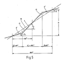
- Fig. 5 the change within a pitch "h” is shown schematically in its development.
- the first Bohrmehlnut 6 this begins at the drill head 2 with the flat pitch angle ⁇ 1 (Bohrmehlnut 6 ') and goes after a rotation angle of the drilling tool of ⁇ 1 ⁇ 90 ° into the steeper pitch angle ⁇ 2.
- This area is identified in FIG. 1 by reference number 6.
- This area is marked in Fig. 1 with 6 ⁇ . Accordingly, the pitch angle changes from ⁇ 1 to ⁇ 2 within a pitch, with a total change in pitch heights after each angular rotation of 180 °.
- the support areas 6 ', 6, 6 ⁇ , d. H. the angular ranges ⁇ 1, ⁇ 2 formed as slope sections with a constant slope.
- the gradient course can also be gradual, i.e. H. with a continuously changing slope.
- Reference number 18 shows a conventional gradient with a constant gradient over a pitch.
- the drill head 2 has a V-shaped or triangular cross-section, as is shown schematically in FIGS. 6 and 7.
- the two side flanks 19, 20 of the drill head 2 are flat or concave in order to form the transition to the drill dust grooves 6, 7.
- the one-piece main cutting plate 21 forms the bisector to the two side flanks 19, 20, wherein an additional secondary cutting plate 22 can preferably be arranged at an acute angle ⁇ to the main cutting plate 21.
- the secondary cutting plate 22 can also be roof-shaped like the main cutting plate 21.
- the angle ⁇ is approximately 40 to 70 °.
- the invention is not restricted to the exemplary embodiment shown and described. Rather, it also encompasses all professional training courses without their own inventive content.
Landscapes
- Engineering & Computer Science (AREA)
- Life Sciences & Earth Sciences (AREA)
- Geology (AREA)
- Mining & Mineral Resources (AREA)
- Mechanical Engineering (AREA)
- Physics & Mathematics (AREA)
- Environmental & Geological Engineering (AREA)
- Fluid Mechanics (AREA)
- General Life Sciences & Earth Sciences (AREA)
- Geochemistry & Mineralogy (AREA)
- Drilling Tools (AREA)
- Processing Of Stones Or Stones Resemblance Materials (AREA)
Applications Claiming Priority (2)
| Application Number | Priority Date | Filing Date | Title |
|---|---|---|---|
| DE3834675A DE3834675A1 (de) | 1988-10-12 | 1988-10-12 | Bohrwerkzeug |
| DE3834675 | 1988-10-12 |
Publications (3)
| Publication Number | Publication Date |
|---|---|
| EP0363734A2 true EP0363734A2 (fr) | 1990-04-18 |
| EP0363734A3 EP0363734A3 (fr) | 1991-03-06 |
| EP0363734B1 EP0363734B1 (fr) | 1993-05-05 |
Family
ID=6364917
Family Applications (1)
| Application Number | Title | Priority Date | Filing Date |
|---|---|---|---|
| EP89117878A Expired - Lifetime EP0363734B1 (fr) | 1988-10-12 | 1989-09-27 | Outil de forage avec hélice d'évacuation |
Country Status (3)
| Country | Link |
|---|---|
| US (1) | US4967855A (fr) |
| EP (1) | EP0363734B1 (fr) |
| DE (2) | DE3834675A1 (fr) |
Cited By (5)
| Publication number | Priority date | Publication date | Assignee | Title |
|---|---|---|---|---|
| EP0655547A3 (fr) * | 1993-11-12 | 1995-11-08 | Hilti Ag | Trépan de roche avec partie transporteuse hélicoidale. |
| EP1190797A1 (fr) | 2000-09-25 | 2002-03-27 | HILTI Aktiengesellschaft | Outil de forage |
| CZ297118B6 (cs) * | 2000-05-05 | 2006-09-13 | Diager | Derovací vrták |
| US7137461B2 (en) | 2002-10-03 | 2006-11-21 | Black & Decker, Inc. | Masonry drilling tool |
| US20150360302A1 (en) * | 2014-06-12 | 2015-12-17 | Kennametal Inc. | Rotary tool and method for manufacturing a rotary tool |
Families Citing this family (32)
| Publication number | Priority date | Publication date | Assignee | Title |
|---|---|---|---|---|
| US5040620A (en) * | 1990-10-11 | 1991-08-20 | Nunley Dwight S | Methods and apparatus for drilling subterranean wells |
| US5918105A (en) * | 1994-12-12 | 1999-06-29 | Black & Decker Inc. | Cutting tools for drilling concrete, aggregate, masonry or the like materials |
| TW299385B (en) | 1994-12-12 | 1997-03-01 | Black & Decker Inc | Cutting tools for drilling concrete, aggregate, masonry or the like materials |
| DE19516270C1 (de) * | 1995-05-09 | 1997-01-30 | Heller Dinklage Gmbh Geb | Bohrwerkzeug |
| US5641028A (en) * | 1995-08-10 | 1997-06-24 | Black & Decker Inc. | Drill bit with debris conveying flute |
| US5704745A (en) * | 1996-09-04 | 1998-01-06 | Credo Tool Company | Chuck sleeve insert for a drill |
| US5915485A (en) * | 1997-01-13 | 1999-06-29 | Mcatavey; Dennis B. | Ski post hole auger bit |
| DE19707115A1 (de) * | 1997-02-22 | 1998-08-27 | Hilti Ag | Bohr- und/oder Meisselwerkzeug |
| US5931615A (en) * | 1997-04-03 | 1999-08-03 | Credo Tool Company | Twist drill bit |
| DE29723908U1 (de) * | 1997-12-04 | 1999-05-27 | Hawera Probst GmbH, 88212 Ravensburg | Gesteinsbohrwerkzeug |
| DE19841978C2 (de) * | 1998-09-14 | 2000-11-23 | Heller Dinklage Gmbh Geb | Bohrer |
| US6321861B1 (en) * | 1999-06-15 | 2001-11-27 | Henry S. Leichter | Auger |
| US6164876A (en) * | 1999-10-30 | 2000-12-26 | Tungsten Industries, Inc | Cutting tool |
| DE10011108A1 (de) * | 2000-03-09 | 2001-09-13 | Hawera Probst Gmbh | Gesteinsbohrer |
| DE10053342A1 (de) * | 2000-10-27 | 2002-05-08 | Hilti Ag | Wendelbohrer |
| DE20108179U1 (de) | 2001-05-15 | 2001-07-26 | Plica Werkzeugfabrik Ag, Mollis | Bohrer |
| DE10243403A1 (de) * | 2002-09-18 | 2004-04-01 | Hawera Probst Gmbh | Verfahren zur Herstellung eines Werkzeugs, insbesondere eines Bohrers oder Fräsers |
| US20030185640A1 (en) * | 2002-03-27 | 2003-10-02 | Eiji Ito | Multiple rake drill bits |
| EP1512476B1 (fr) * | 2003-09-08 | 2013-10-09 | Black & Decker Inc. | Foret à auto-centrage avec pointe pilote |
| WO2007107129A1 (fr) * | 2006-03-23 | 2007-09-27 | Technische Universität Dresden | FRAISEUSE cylindrique A LAME DE COUPE DE FORME HELICOIDALE |
| US20090148250A1 (en) * | 2007-12-05 | 2009-06-11 | Wayne Chappell | Drill Bit |
| US8074561B2 (en) * | 2008-06-24 | 2011-12-13 | Pio Galbis | Device and method for cleaning a french or coffee press |
| US7861807B2 (en) * | 2008-12-03 | 2011-01-04 | Black & Decker Inc. | Drill bit including one piece cutting head |
| JP5067441B2 (ja) * | 2009-06-30 | 2012-11-07 | イビデン株式会社 | 切削ドリル及びプリント配線板の製造方法 |
| EP2502710B1 (fr) | 2011-03-22 | 2020-04-22 | Black & Decker Inc. | Ciseaux |
| DE102011016686A1 (de) * | 2011-04-11 | 2012-10-11 | Illinois Tool Works Inc. | Gesteinsbohrer |
| CN102305034A (zh) * | 2011-08-24 | 2012-01-04 | 成都科盛石油科技有限公司 | 用于浅层土质的钻井工具 |
| USD734792S1 (en) | 2013-03-15 | 2015-07-21 | Black & Decker Inc. | Drill bit |
| USD737875S1 (en) | 2013-03-15 | 2015-09-01 | Black & Decker Inc. | Drill bit |
| US9333564B2 (en) | 2013-03-15 | 2016-05-10 | Black & Decker Inc. | Drill bit |
| EP3063363B1 (fr) * | 2013-10-25 | 2020-11-25 | National Oilwell Varco, L.P. | Raccords de nettoyage de trou pour fond de trou et leurs procédés d'utilisation |
| DE102014212714B4 (de) | 2014-07-01 | 2022-02-17 | Kennametal Inc. | Bohrerkopf |
Family Cites Families (15)
| Publication number | Priority date | Publication date | Assignee | Title |
|---|---|---|---|---|
| US455824A (en) * | 1891-07-14 | Mining-machine | ||
| DE333896C (de) * | 1920-03-18 | 1921-03-05 | Siemens Schuckertwerke G M B H | Verfahren und Bohrer zur Erzielung eines Vorschubes fuer Gesteinsdrehbohrmaschinen |
| US2084737A (en) * | 1935-07-05 | 1937-06-22 | William J Neumann | Reamer |
| US2876995A (en) * | 1954-09-02 | 1959-03-10 | Sr Francis M Neighly | Percussion drills |
| US2981403A (en) * | 1957-04-15 | 1961-04-25 | Joy Mfg Co | Conveying apparatus |
| DE1291707B (de) * | 1965-03-13 | 1969-04-03 | Hawera Probst Kg Hartmetall | Gesteinsbohrer |
| DE1927754C3 (de) * | 1969-05-30 | 1978-12-14 | Hawera Probst Gmbh + Co, 7980 Ravensburg | Gesteinsbohrer |
| DE2013328B1 (de) * | 1970-03-20 | 1971-07-15 | Werkzeugbau Gmbh, 8130 Starnberg | Gesteinsbohrer |
| DE2059232B1 (de) * | 1970-12-02 | 1972-03-09 | Werkzeugbau Gmbh | Gesteinsbohrer |
| DE2129913A1 (de) * | 1971-06-16 | 1972-12-21 | Hilti Ag | Gesteinsbohrer |
| DE2159728A1 (de) * | 1971-12-02 | 1973-06-07 | Heller Geb | Hammerbohrer |
| DE2735227C2 (de) * | 1977-08-04 | 1983-10-27 | Hawera Probst Gmbh + Co, 7980 Ravensburg | Gesteinsbohrer |
| DE2756140A1 (de) * | 1977-12-16 | 1979-06-21 | Heinrich B Schaefers | Gesteinsbohrer fuer bohrloecher kleineren durchmessers |
| DE3317989A1 (de) * | 1983-05-18 | 1984-11-22 | Hawera Probst Gmbh + Co, 7980 Ravensburg | Bohrwerkzeug |
| JPS60207711A (ja) * | 1984-03-31 | 1985-10-19 | Morio Kitani | 大捻角、大スクイ角の円筒面捻刃、円錐捻刃のボ−ルエンドミル |
-
1988
- 1988-10-12 DE DE3834675A patent/DE3834675A1/de not_active Withdrawn
-
1989
- 1989-09-25 US US07/411,819 patent/US4967855A/en not_active Expired - Fee Related
- 1989-09-27 DE DE8989117878T patent/DE58904273D1/de not_active Expired - Fee Related
- 1989-09-27 EP EP89117878A patent/EP0363734B1/fr not_active Expired - Lifetime
Cited By (6)
| Publication number | Priority date | Publication date | Assignee | Title |
|---|---|---|---|---|
| EP0655547A3 (fr) * | 1993-11-12 | 1995-11-08 | Hilti Ag | Trépan de roche avec partie transporteuse hélicoidale. |
| CZ297118B6 (cs) * | 2000-05-05 | 2006-09-13 | Diager | Derovací vrták |
| EP1190797A1 (fr) | 2000-09-25 | 2002-03-27 | HILTI Aktiengesellschaft | Outil de forage |
| US7137461B2 (en) | 2002-10-03 | 2006-11-21 | Black & Decker, Inc. | Masonry drilling tool |
| US20150360302A1 (en) * | 2014-06-12 | 2015-12-17 | Kennametal Inc. | Rotary tool and method for manufacturing a rotary tool |
| US9623489B2 (en) * | 2014-06-12 | 2017-04-18 | Kennametal Inc. | Rotary tool and method for manufacturing a rotary tool |
Also Published As
| Publication number | Publication date |
|---|---|
| US4967855A (en) | 1990-11-06 |
| EP0363734B1 (fr) | 1993-05-05 |
| DE58904273D1 (de) | 1993-06-09 |
| DE3834675A1 (de) | 1990-04-19 |
| EP0363734A3 (fr) | 1991-03-06 |
Similar Documents
| Publication | Publication Date | Title |
|---|---|---|
| EP0363734B1 (fr) | Outil de forage avec hélice d'évacuation | |
| EP2237913B1 (fr) | Outil de perçage et pointe correspondante | |
| EP0126409B2 (fr) | Outil de forage | |
| EP0073926B1 (fr) | Outil de coupe, en particulier plaquette amovible | |
| EP0657617A1 (fr) | Trépan de roche | |
| EP0322565B1 (fr) | Trépan de roche | |
| EP1050662B1 (fr) | Outil de forage pour roche | |
| EP1260296B1 (fr) | Foret | |
| EP1259699A2 (fr) | Perforatrice de roches | |
| DE102011085187B3 (de) | Bohrer und Herstellungsverfahren für einen Bohrer | |
| EP0749794A1 (fr) | Outil de perçage | |
| WO2008080748A1 (fr) | Foret de forage de trous profonds doté d'une bague de soutien et procédé pour sa fabrication | |
| DE102007062539B4 (de) | Bohrwerkzeug | |
| EP1261798A2 (fr) | Outil de forage de roche | |
| EP0653544B1 (fr) | Foret hélicoidal | |
| EP0730082A2 (fr) | Tête de forage pour forage rotatif avec percussion | |
| DE20303656U1 (de) | Stufenbohrer | |
| EP0054913A2 (fr) | Outil d'alésage | |
| DE1927754C3 (de) | Gesteinsbohrer | |
| DE2013328B1 (de) | Gesteinsbohrer | |
| EP0322554B1 (fr) | Trépan de roche | |
| DE3324440A1 (de) | Voll-bohrer | |
| DE102017117664A1 (de) | Bohrer | |
| DE2013327B1 (de) | Gesteinsbohrer fur Drehschlagbohr maschinen | |
| EP2818289B1 (fr) | Tige de foret à pierre et son procédé de fabrication |
Legal Events
| Date | Code | Title | Description |
|---|---|---|---|
| PUAI | Public reference made under article 153(3) epc to a published international application that has entered the european phase |
Free format text: ORIGINAL CODE: 0009012 |
|
| AK | Designated contracting states |
Kind code of ref document: A2 Designated state(s): CH DE FR GB IT LI |
|
| PUAL | Search report despatched |
Free format text: ORIGINAL CODE: 0009013 |
|
| AK | Designated contracting states |
Kind code of ref document: A3 Designated state(s): CH DE FR GB IT LI |
|
| 17P | Request for examination filed |
Effective date: 19910824 |
|
| 17Q | First examination report despatched |
Effective date: 19921015 |
|
| GRAA | (expected) grant |
Free format text: ORIGINAL CODE: 0009210 |
|
| AK | Designated contracting states |
Kind code of ref document: B1 Designated state(s): CH DE FR GB IT LI |
|
| REF | Corresponds to: |
Ref document number: 58904273 Country of ref document: DE Date of ref document: 19930609 |
|
| ET | Fr: translation filed | ||
| GBT | Gb: translation of ep patent filed (gb section 77(6)(a)/1977) |
Effective date: 19930524 |
|
| ITF | It: translation for a ep patent filed | ||
| PLBE | No opposition filed within time limit |
Free format text: ORIGINAL CODE: 0009261 |
|
| STAA | Information on the status of an ep patent application or granted ep patent |
Free format text: STATUS: NO OPPOSITION FILED WITHIN TIME LIMIT |
|
| 26N | No opposition filed | ||
| PGFP | Annual fee paid to national office [announced via postgrant information from national office to epo] |
Ref country code: CH Payment date: 19951201 Year of fee payment: 7 |
|
| PG25 | Lapsed in a contracting state [announced via postgrant information from national office to epo] |
Ref country code: LI Effective date: 19960930 Ref country code: CH Effective date: 19960930 |
|
| REG | Reference to a national code |
Ref country code: CH Ref legal event code: PL |
|
| PGFP | Annual fee paid to national office [announced via postgrant information from national office to epo] |
Ref country code: GB Payment date: 19970926 Year of fee payment: 9 |
|
| PGFP | Annual fee paid to national office [announced via postgrant information from national office to epo] |
Ref country code: FR Payment date: 19970930 Year of fee payment: 9 |
|
| PG25 | Lapsed in a contracting state [announced via postgrant information from national office to epo] |
Ref country code: GB Free format text: LAPSE BECAUSE OF NON-PAYMENT OF DUE FEES Effective date: 19980927 |
|
| PGFP | Annual fee paid to national office [announced via postgrant information from national office to epo] |
Ref country code: DE Payment date: 19981007 Year of fee payment: 10 |
|
| GBPC | Gb: european patent ceased through non-payment of renewal fee |
Effective date: 19980927 |
|
| PG25 | Lapsed in a contracting state [announced via postgrant information from national office to epo] |
Ref country code: FR Free format text: LAPSE BECAUSE OF NON-PAYMENT OF DUE FEES Effective date: 19990531 |
|
| REG | Reference to a national code |
Ref country code: FR Ref legal event code: ST |
|
| PG25 | Lapsed in a contracting state [announced via postgrant information from national office to epo] |
Ref country code: DE Free format text: LAPSE BECAUSE OF NON-PAYMENT OF DUE FEES Effective date: 20000701 |
|
| PG25 | Lapsed in a contracting state [announced via postgrant information from national office to epo] |
Ref country code: IT Free format text: LAPSE BECAUSE OF NON-PAYMENT OF DUE FEES;WARNING: LAPSES OF ITALIAN PATENTS WITH EFFECTIVE DATE BEFORE 2007 MAY HAVE OCCURRED AT ANY TIME BEFORE 2007. THE CORRECT EFFECTIVE DATE MAY BE DIFFERENT FROM THE ONE RECORDED. Effective date: 20050927 |