EP0363799A1 - Tête de pulvérisateur pour atomiser un matériau hautement polymère thermoplastique - Google Patents
Tête de pulvérisateur pour atomiser un matériau hautement polymère thermoplastique Download PDFInfo
- Publication number
- EP0363799A1 EP0363799A1 EP89118392A EP89118392A EP0363799A1 EP 0363799 A1 EP0363799 A1 EP 0363799A1 EP 89118392 A EP89118392 A EP 89118392A EP 89118392 A EP89118392 A EP 89118392A EP 0363799 A1 EP0363799 A1 EP 0363799A1
- Authority
- EP
- European Patent Office
- Prior art keywords
- spray head
- outlet openings
- feed channel
- head according
- melt adhesive
- Prior art date
- Legal status (The legal status is an assumption and is not a legal conclusion. Google has not performed a legal analysis and makes no representation as to the accuracy of the status listed.)
- Ceased
Links
- 239000007921 spray Substances 0.000 title claims abstract description 67
- 239000000463 material Substances 0.000 title claims abstract description 33
- 229920001169 thermoplastic Polymers 0.000 title claims abstract description 6
- 239000004416 thermosoftening plastic Substances 0.000 title claims abstract description 6
- 239000004831 Hot glue Substances 0.000 claims abstract description 38
- 238000005507 spraying Methods 0.000 claims description 7
- 239000002861 polymer material Substances 0.000 claims description 6
- 230000009969 flowable effect Effects 0.000 claims description 3
- 238000006073 displacement reaction Methods 0.000 description 6
- 239000000758 substrate Substances 0.000 description 4
- 239000000853 adhesive Substances 0.000 description 3
- 230000001070 adhesive effect Effects 0.000 description 3
- 239000007788 liquid Substances 0.000 description 3
- 238000000034 method Methods 0.000 description 3
- 238000010438 heat treatment Methods 0.000 description 2
- 238000004519 manufacturing process Methods 0.000 description 2
- 239000003637 basic solution Substances 0.000 description 1
- 230000015572 biosynthetic process Effects 0.000 description 1
- 238000011109 contamination Methods 0.000 description 1
- 238000001816 cooling Methods 0.000 description 1
- 230000000694 effects Effects 0.000 description 1
- 230000010354 integration Effects 0.000 description 1
- 238000013021 overheating Methods 0.000 description 1
- 230000002028 premature Effects 0.000 description 1
- 239000007787 solid Substances 0.000 description 1
- 238000007711 solidification Methods 0.000 description 1
- 230000008023 solidification Effects 0.000 description 1
- 230000007704 transition Effects 0.000 description 1
Images

Classifications
-
- B—PERFORMING OPERATIONS; TRANSPORTING
- B05—SPRAYING OR ATOMISING IN GENERAL; APPLYING FLUENT MATERIALS TO SURFACES, IN GENERAL
- B05B—SPRAYING APPARATUS; ATOMISING APPARATUS; NOZZLES
- B05B7/00—Spraying apparatus for discharge of liquids or other fluent materials from two or more sources, e.g. of liquid and air, of powder and gas
- B05B7/02—Spray pistols; Apparatus for discharge
- B05B7/08—Spray pistols; Apparatus for discharge with separate outlet orifices, e.g. to form parallel jets, i.e. the axis of the jets being parallel, to form intersecting jets, i.e. the axis of the jets converging but not necessarily intersecting at a point
- B05B7/0807—Spray pistols; Apparatus for discharge with separate outlet orifices, e.g. to form parallel jets, i.e. the axis of the jets being parallel, to form intersecting jets, i.e. the axis of the jets converging but not necessarily intersecting at a point to form intersecting jets
- B05B7/0861—Spray pistols; Apparatus for discharge with separate outlet orifices, e.g. to form parallel jets, i.e. the axis of the jets being parallel, to form intersecting jets, i.e. the axis of the jets converging but not necessarily intersecting at a point to form intersecting jets with one single jet constituted by a liquid or a mixture containing a liquid and several gas jets
Definitions
- the invention relates to a spray head for spraying a thermoplastic, high polymer material, in particular a hot melt adhesive, of the type specified in the preamble of claim 1.
- Such a spray head emerges from DE-PS 35 43 469 and has at least a first feed channel for the heated and thus flowable material, a second feed channel for a gas stream, a mixing chamber connected to the two feed channels, a nozzle opening in the mixing chamber for the outlet of the atomized material, a third feed channel for a further gas stream and outlet openings formed on the underside of the spray head and connected to the third feed channel for gas jets directed towards the emerging, atomized material.
- the gas jets run from the outlet openings, seen in a top view of the nozzle opening, parallel to one another and past the nozzle opening, so that one can give the emerging, atomized and thus easily influenced material a certain shape and directional component, as required for certain application processes is.
- certain spray patterns can be achieved, especially relatively elongated, oval patterns; will If such patterns are generated by several spray heads arranged side by side, they partially overlap, so that an optimal area coverage can be achieved.
- a disadvantage of the known spray head is the relatively complex structure with the separate, externally attachable additional parts and with the corresponding, complex control.
- the invention is therefore based on the object of creating a spray head of the type specified, in which the disadvantages mentioned above do not occur.
- a spray head which has a simple and compact structure and ensures a completely stable, uniform deflection of the emerging material flow.
- the advantages achieved by the invention are based on the integration of the outlet openings for the gas jets into the spray head itself, so that no additional parts which can be attached to the outside of the spray head are required.
- the result is a simple, closed structure that is easy to handle and also to maintain.
- the gas jets directed from the side onto the atomized material are heated in the spray head and are thus at a precisely defined temperature, which corresponds approximately to the temperature of the material, so that there can be no unwanted cooling and thus unfavorable influence on the material application , how it can not be avoided with the external application of gas jets from the outside without additional heating.
- the outlet openings for the gas jets are directed obliquely downwards, so that the atomized material on the one hand and the gas jets on the other hand have a common directional component, namely perpendicularly downwards; this concurrent flow of the control gas jets results in a very stable deflection; In particular, the unstable, direction-changing flow vortices can be avoided, as they occur in the spray button according to US Pat. No. 4,711,683 due to the opposite flow directions of gas jets and material.
- the spray head according to DE-PS 35 43 469 is not suitable for lateral deflection and thus for displacing the escaping, sprayed material, since the gas jets, seen in plan view of the nozzle opening, pass parallel to one another at the nozzle opening, which only causes a deformation of the Spray pattern, but no displacement of the sprayed material results.
- the effects of the two outlet openings for the gas jets essentially compensate, so that a displacement of the spray pattern is excluded.
- outlet openings for the gas jets run at an angle of approximately 45 ° to the flat underside of the spray head, with deviations of up to 15 to 20 ° being possible on each side.
- two side-by-side outlet openings for the gas jets may be sufficient for some applications, according to a preferred embodiment more than two outlet openings are used, in particular three or four outlet openings which are arranged side by side on a circumference on one side of the spray head on its underside.
- the lower part of the spray head is designed as a removable, approximately cup-shaped nozzle body which is screwed onto the underside of the spray head. You can then keep different nozzle bodies in readiness for different applications, which can be screwed onto the spray head as required.
- thermoplastic, high-polymer materials in particular hot melt adhesives
- a liquefaction device 12 which can have the structure known from DE-PS 28 36 545.
- the liquefaction device 12 has on its top a fill cap 14 for the high-polymer material to be refilled.
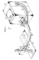
- the device 10 contains a hose 16, which is shown larger in the left part of FIG. 1 than in the right part.
- This hose 16 opens into a spray head 18, on the underside of which a spray nozzle 19 is provided for spraying the hot melt adhesive onto a material web 20 which is moved in the direction of the arrow and is to be coated with the hot melt adhesive; the emerging, sprayed hot melt adhesive is indicated in Fig. 1 with dashed lines.
- the material web 20 can be, for example, a cushioning material such as is used for the production of hygienic articles, in particular baby diapers. Then elastic threads or tapes are applied to the spray track under pre-tension and thereby connected to the material web, whereby the material web contracts and curls, as z. B. is required for the leg closure of baby diapers.
- the hose 16 has at its inlet end a connector 22 and at its outlet end on a connecting piece 24 which are fastened to the liquefaction device 12 or the spray head 18 by corresponding counterparts.
- a compressed air inlet hose 28 which opens into a shut-off element designed as a solenoid valve 30, which is acted upon by the compressed air flowing in the direction of the arrow, and two connected to the condensing device 12 via plugs Lines, namely a supply line 32 connected to a heating tape in the interior of the hose 16 and a control line 34.
- an outlet hose 36 for warm air penetrates the outer wall of the hose 16 and opens into the underside of the spray head 18.
- the hose 16 has, for example, the structure as is known from DE-OS 3 416 105, d. that is, the air line is integrated in the hose 16, so that the compressed air supplied and the heated hot melt adhesive in the hose 16 are kept at a predetermined temperature.
- hose 16 and compressed air line can also be designed separately.
- the compressed air line branches in front of the solenoid valve 30, ie a line leads to the solenoid valve 30, while a bypass 38 bypassing the solenoid valve 30 is reconnected to the compressed air hose 28 at a point which is downstream of the solenoid valve 30 when viewed in the flow direction is.
- a small amount of compressed air flows through this bypass 38 in comparison with the amount of operating air, not only during a spraying process but also during the breaks in operation.
- the spray device 10 shown in FIG. 1 has the following mode of operation: in the liquefaction device 12, the usually solid or at least highly viscous hot melt adhesive filled through the cover 14 is heated and thereby liquefied; since the shut-off device for the supply of the liquefied hot melt adhesive is still closed (this shut-off device is generally located in the liquefaction device 12 and is not shown in FIG. 1), no hot melt adhesive can escape at the spray head 18.
- a corresponding switching signal is given, whereby the valve 30 in the compressed air line 28 and the shut-off element of the liquefaction device 12 are opened at the same time.
- the heated and thereby liquefied hot melt adhesive is conducted with a high pressure displacement pump (not shown) in the liquefaction device 12 via the connection 14 into the hose 16.
- the solenoid valve 30 is opened so that the entire amount of compressed air available flows through the hose 16 and the air hose 36 into the spray head 18 via the solenoid valve 30 and the air hose 28.
- the hot-melt adhesive leaves the hose 16 via the nozzle 24 at approximately the same temperature that it has when entering the hose 16;
- the compressed air also leaves the hose 16 via the gas line part 36 at approximately the same temperature as the hot melt adhesive.
- the compressed air heated in this way is introduced into the spray head 18 into the hot-melt adhesive stream in such a way that it is atomized, the temperature-controlled air stream being at such a temperature that on the one hand it does not lead to premature solidification of the hot-melt adhesive applied, but on the other hand does not lead to overheating of the hot-melt adhesive and thus impairing its properties when leaving the spray head 18.
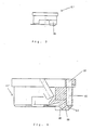
- Fig. 2 shows a vertical section through the lower part of the spray head 18 with the spray nozzle 19 and a screwed, approximately cup-shaped nozzle body 41.
- This nozzle carrier 42 is approximately cylindrical in shape and has in its central feed channel 40 for the heated hot melt adhesive a displaceable valve needle 44 with a tip, which extends to the lower end of the feed channel 40 and thus of the nozzle carrier 42.
- the central feed channel 40 for the heated hotmelt adhesive also tapers, so that a valve seat is created which can be closed by the tip of the valve needle 44. This stops the material supply.
- a control valve 60 for the compressed air is provided on the left side of the nozzle carrier 42 as shown in FIG. 2, so that the amount and / or the pressure of the compressed air supplied to the spray head 18 can be adjusted.
- the control valve 60 is connected to the line 36 for the compressed air (see FIG. 1).
- a flow channel 46 runs downward in the nozzle carrier 42 and opens into an annular channel 48 which is formed between a stepped channel with a reduced diameter of the nozzle carrier 42 on the inside and the inside wall of the nozzle body 41 on the outside is. From this ring channel 48, the compressed air flows through an inward and downward channel into a mixing chamber which is delimited at the lower end by the inner wall of the nozzle body 41 on the one hand and the lower, conical end of the nozzle carrier 42 on the other and in turn tapers downwards.
- the compressed air on the one hand and the liquid hot melt adhesive on the other hand are fed to the mixing chamber and mixed there.
- the nozzle body 41 has an outlet opening 80 for the atomized hot melt adhesive, so that the atomized hot melt adhesive leaves the outlet opening 80 as a “hot melt adhesive curtain” and can be applied to the substrate 20 as a uniform, thin layer.
- the nozzle holder 42 contains a second compressed air connection 62 with a second control valve 64, which can be switched in a clocked, intermittent manner.
- This connection 62 is connected via a flow channel 66 in the nozzle carrier 42 to a flow channel 68 in the nozzle body 41.
- a half-ring line (not shown) in the transition region between the nozzle carrier 42 and the nozzle body 41 connects the two channels 66, 68 to a further flow channel 70 on the opposite side of the nozzle body 41, i. that is, the two flow channels 68, 70 in the nozzle body 41 are arranged symmetrically to the center of the nozzle body 41.
- the two flow channels 68, 70 in the nozzle body 41 end in hemispherical knobs 72, 74 which are located on the lower outside of the nozzle body 41 and are provided with outlet openings 76, 78.
- outlet openings 76, 78 are directed obliquely downwards onto the atomized hot melt adhesive, which leaves the nozzle body 41 via the outlet opening 80.
- the two knobs 72, 74 and the outlet opening 80 of the nozzle body 41 lie on a straight line.
- the outlet openings 76, 78 of the knobs 72, 74 are arranged parallel to one another in such a way that the exiting air jets flow past the outlet opening 80, ie the "hot melt adhesive curtain" exiting from the outlet opening 80 is blown from both sides by the air jets from the knobs 72 , 74 acted upon and thereby receives a certain shape, which in turn allows a defined spray pattern to be set.
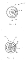
- the nozzle body 41 of the spray head 18, as is already known from DE-PS 35 43 469, is now replaced by the embodiment 41 'according to FIGS. 3 to 6, which is screwed onto the nozzle holder 42 in the same way.
- This nozzle body 41 has on its top in the middle a recess which, together with the opposite end of the nozzle holder 42, forms the mixing chamber in which the liquefied hot melt adhesive from the central feed channel 40 and the compressed air from the feed channel 46 (see Fig. 2) meet.
- annular channel 81 At the edge region in the nozzle carrier 42 facing the top of the nozzle body 41 'a short annular channel 81 is formed, in which on the one hand the feed channel 66 (see Fig. 2) and on the other hand four outlet bores 82 of the nozzle body 41' open. As can be seen in FIG. 5, these bores 82 extend radially obliquely downwards from the annular channel in the nozzle body 41; the four radii assigned to the bores 82 each form an angle of 20 ° with one another, so that the four bores 82 enclose a central angle of approximately 80 °.
- the nozzle body 41 ' is asymmetrical, d. 3, 4 on the right-hand side, the nozzle body 41 'is provided on its underside with a projection 84 which has approximately the shape of a partial ring and extends approximately over an angle of 90 ° (see FIG Fig. 5).
- the projection 84 is on its outlet opening 80 facing, in section partially circular inside with a beveled surface 86 which is approximately at an angle of 45 ° to the inner surface of the nozzle body 41 'with the outlet opening 80 or the flat underside 86 of the projection 84th extends.
- the bores 82 extend from the annular channel 81 in the top of the nozzle body 41 'initially axially downward and then open into an inclined end region 89 with an outlet opening in the inclined surface 88.
- the compressed air passes through the feed line 46 and the liquid hot melt adhesive via the feed line 40 into the mixing chamber, where they are mixed and thus the liquid hot melt adhesive is atomized, so that a "hot melt adhesive curtain" emerges from the outlet opening 80 downwards.
- valve 64 is still closed, so that a strip-shaped spray pattern results on the substrate 20 due to the relative movement between the spray head 18 and the substrate 20.
- the total of four gas jets that are generated in the embodiment according to FIGS. 3 to 6 envelop the emerging hot melt adhesive curtain from all sides and simultaneously move it (as shown in FIGS. 4 and 3) to the left, so that a new one , parallel offset spray track results.
- this displacement movement can be interrupted, ie, now the hot melt adhesive curtain emerges unhindered from the outlet opening 80 and generates the normal spray pattern again.
- the air jets emerging from the four bores 89 form a closed “pressure wall” which completely envelops the “hot melt adhesive curtain” on one side and therefore shifts it uniformly parallel, which results in the displacement of the spray track.
- the displacement distance can be adjusted on the one hand by the spatial arrangement of the outlet openings of the bores 89, but also on the other hand by the pressure or speed of the emerging air jets.
- Appropriate settings can be made by varying the number, but also the position, in particular the angular position of the bores 89. It is therefore advisable to keep several nozzle bodies 41 'in readiness, which are screwed onto the nozzle holder 42 as required if the corresponding settings have to be implemented.
Landscapes
- Nozzles (AREA)
Applications Claiming Priority (2)
| Application Number | Priority Date | Filing Date | Title |
|---|---|---|---|
| DE8812808U | 1988-10-12 | ||
| DE8812808U DE8812808U1 (de) | 1988-10-12 | 1988-10-12 | Sprühkopf zum Versprühen eines thermoplastischen, hochpolymeren Werkstoffes |
Publications (1)
| Publication Number | Publication Date |
|---|---|
| EP0363799A1 true EP0363799A1 (fr) | 1990-04-18 |
Family
ID=6828786
Family Applications (1)
| Application Number | Title | Priority Date | Filing Date |
|---|---|---|---|
| EP89118392A Ceased EP0363799A1 (fr) | 1988-10-12 | 1989-10-04 | Tête de pulvérisateur pour atomiser un matériau hautement polymère thermoplastique |
Country Status (3)
| Country | Link |
|---|---|
| EP (1) | EP0363799A1 (fr) |
| JP (1) | JPH0622708B2 (fr) |
| DE (1) | DE8812808U1 (fr) |
Cited By (2)
| Publication number | Priority date | Publication date | Assignee | Title |
|---|---|---|---|---|
| EP0686435A1 (fr) | 1994-04-29 | 1995-12-13 | Dow Corning Corporation | Procédé et dispositif permettant d'appliquer des composites organosiloxanes en fusion durcis en humidité |
| AU2005301408B2 (en) * | 2004-11-04 | 2012-04-05 | Manufacturing Systems Limited | Tile coating and process therefor |
Families Citing this family (1)
| Publication number | Priority date | Publication date | Assignee | Title |
|---|---|---|---|---|
| JP4987430B2 (ja) * | 2006-11-08 | 2012-07-25 | 株式会社ニレコ | マーキングノズル装置 |
Citations (6)
| Publication number | Priority date | Publication date | Assignee | Title |
|---|---|---|---|---|
| AT186761B (de) * | 1952-09-29 | 1956-09-10 | August Harder | Spritzkopf für Spritzpistolen |
| DE1066919B (fr) * | 1957-10-21 | 1959-10-08 | ||
| US4228958A (en) * | 1979-07-27 | 1980-10-21 | General Motors Corporation | Air-operated spray device |
| US4657184A (en) * | 1986-01-31 | 1987-04-14 | Champion Spark Plug Company | Fluid tip and air cap assembly |
| US4711683A (en) * | 1987-03-09 | 1987-12-08 | Paper Converting Machine Company | Method and apparatus for making elastic diapers |
| DE3543469C2 (fr) * | 1985-12-09 | 1988-02-25 | Henning J. 2120 Lueneburg De Claassen |
-
1988
- 1988-10-12 DE DE8812808U patent/DE8812808U1/de not_active Expired - Lifetime
-
1989
- 1989-10-04 EP EP89118392A patent/EP0363799A1/fr not_active Ceased
- 1989-10-12 JP JP26606089A patent/JPH0622708B2/ja not_active Expired - Lifetime
Patent Citations (6)
| Publication number | Priority date | Publication date | Assignee | Title |
|---|---|---|---|---|
| AT186761B (de) * | 1952-09-29 | 1956-09-10 | August Harder | Spritzkopf für Spritzpistolen |
| DE1066919B (fr) * | 1957-10-21 | 1959-10-08 | ||
| US4228958A (en) * | 1979-07-27 | 1980-10-21 | General Motors Corporation | Air-operated spray device |
| DE3543469C2 (fr) * | 1985-12-09 | 1988-02-25 | Henning J. 2120 Lueneburg De Claassen | |
| US4657184A (en) * | 1986-01-31 | 1987-04-14 | Champion Spark Plug Company | Fluid tip and air cap assembly |
| US4711683A (en) * | 1987-03-09 | 1987-12-08 | Paper Converting Machine Company | Method and apparatus for making elastic diapers |
Cited By (3)
| Publication number | Priority date | Publication date | Assignee | Title |
|---|---|---|---|---|
| EP0686435A1 (fr) | 1994-04-29 | 1995-12-13 | Dow Corning Corporation | Procédé et dispositif permettant d'appliquer des composites organosiloxanes en fusion durcis en humidité |
| US5505997A (en) * | 1994-04-29 | 1996-04-09 | Dow Corning Corporation | Method and apparatus for applying coatings of molten moisture curable organosiloxane compositions |
| AU2005301408B2 (en) * | 2004-11-04 | 2012-04-05 | Manufacturing Systems Limited | Tile coating and process therefor |
Also Published As
| Publication number | Publication date |
|---|---|
| DE8812808U1 (de) | 1990-02-08 |
| JPH0622708B2 (ja) | 1994-03-30 |
| JPH02227154A (ja) | 1990-09-10 |
Similar Documents
| Publication | Publication Date | Title |
|---|---|---|
| DE69420186T3 (de) | Vernebler | |
| DE3879920T3 (de) | Spritzdüse für Dosierkopf mit einer Zahnradpumpe. | |
| DE68924079T2 (de) | Sprühpistole. | |
| EP0225624B1 (fr) | Tête de pulvérisation pour matière thermoplastique, en particulier pour un adhésif fusible | |
| DE68901951T2 (de) | Luftzerstaeubungsgeraet fuer fluessigkeiten. | |
| DE69329539T2 (de) | Spritzpistole für Substratbeschichtung | |
| DE69224032T2 (de) | Verfahren und Vorrichtung zum Abgeben von mehreren Streifen einer viskosen Flüssigkeit | |
| EP0850697B1 (fr) | Dispositif pour l'application de matériaux fluides sur un substrat, en particulier pour l'application intermittente de colles fluides | |
| DE4230535C2 (de) | Zweikomponenten-Spritzpistole | |
| DE8534594U1 (de) | Sprühkopf zum Versprühen eines thermoplastischen Kunststoffes, insbesondere eines Schmelzklebstoffes | |
| DE10059406B4 (de) | Spritzvorrichtung | |
| DE102014010843B4 (de) | Dosierdüse und Verfahren zum dosierten Auftragen hochviskoser Medien | |
| DE68920950T2 (de) | Düsenvorsatz für eine Klebepistole. | |
| EP0345670B1 (fr) | Tête de pulvérisation pour humidificateur à buses et procédé d'humidification | |
| EP3829778B1 (fr) | Jeu de buses pour un pistolet pulvérisateur, système de pistolet pulvérisateur, procédé de réalisation d'un module de buses, procédé de sélection d'un module de buses d'un jeu de buses pour un travail de peinture, système de sélection et produit-programme informatique | |
| EP2228138A1 (fr) | Dispositif de revêtement d'un substrat | |
| DE3238201A1 (de) | Spruehkopf, insbesondere zum auftragen und verteilen von trennmittel auf druck- und spritzgussformen | |
| DE20017630U1 (de) | Farbspritzpistole | |
| DE2757522C2 (de) | Rund- oder Ringstrahldüse zum Erzeugen und Abstrahlen eines Nebels oder Aerosols zur Beschichtung von Gegenständen | |
| DE3540619C1 (de) | Vorrichtung zum Verspruehen von klebrigen Auftragmassen | |
| EP0363799A1 (fr) | Tête de pulvérisateur pour atomiser un matériau hautement polymère thermoplastique | |
| DE19507365A1 (de) | Vorrichtung zum Versprühen eines Zweistoffgemisches | |
| DE2702191B2 (de) | Spritzvorrichtung zum Zerstäuben von Flüssigkeiten | |
| DE3604147A1 (de) | Spritzpistole | |
| EP1203613A1 (fr) | Buse multiple pour pulvériser une substance |
Legal Events
| Date | Code | Title | Description |
|---|---|---|---|
| PUAI | Public reference made under article 153(3) epc to a published international application that has entered the european phase |
Free format text: ORIGINAL CODE: 0009012 |
|
| AK | Designated contracting states |
Kind code of ref document: A1 Designated state(s): AT BE CH DE ES FR GB GR IT LI LU NL SE |
|
| 17P | Request for examination filed |
Effective date: 19901002 |
|
| 17Q | First examination report despatched |
Effective date: 19910916 |
|
| STAA | Information on the status of an ep patent application or granted ep patent |
Free format text: STATUS: THE APPLICATION HAS BEEN REFUSED |
|
| 18R | Application refused |
Effective date: 19920314 |