EP0363951A2 - Vérin pour chariot à fourche - Google Patents
Vérin pour chariot à fourche Download PDFInfo
- Publication number
- EP0363951A2 EP0363951A2 EP89118961A EP89118961A EP0363951A2 EP 0363951 A2 EP0363951 A2 EP 0363951A2 EP 89118961 A EP89118961 A EP 89118961A EP 89118961 A EP89118961 A EP 89118961A EP 0363951 A2 EP0363951 A2 EP 0363951A2
- Authority
- EP
- European Patent Office
- Prior art keywords
- ball
- fork
- valve
- spring
- channel
- Prior art date
- Legal status (The legal status is an assumption and is not a legal conclusion. Google has not performed a legal analysis and makes no representation as to the accuracy of the status listed.)
- Withdrawn
Links
Images


Classifications
-
- B—PERFORMING OPERATIONS; TRANSPORTING
- B62—LAND VEHICLES FOR TRAVELLING OTHERWISE THAN ON RAILS
- B62B—HAND-PROPELLED VEHICLES, e.g. HAND CARTS OR PERAMBULATORS; SLEDGES
- B62B3/00—Hand carts having more than one axis carrying transport wheels; Steering devices therefor; Equipment therefor
- B62B3/04—Hand carts having more than one axis carrying transport wheels; Steering devices therefor; Equipment therefor involving means for grappling or securing in place objects to be carried; Loading or unloading equipment
- B62B3/06—Hand carts having more than one axis carrying transport wheels; Steering devices therefor; Equipment therefor involving means for grappling or securing in place objects to be carried; Loading or unloading equipment for simply clearing the load from the ground
- B62B3/0618—Hand carts having more than one axis carrying transport wheels; Steering devices therefor; Equipment therefor involving means for grappling or securing in place objects to be carried; Loading or unloading equipment for simply clearing the load from the ground using fluid lifting mechanisms
-
- B—PERFORMING OPERATIONS; TRANSPORTING
- B62—LAND VEHICLES FOR TRAVELLING OTHERWISE THAN ON RAILS
- B62B—HAND-PROPELLED VEHICLES, e.g. HAND CARTS OR PERAMBULATORS; SLEDGES
- B62B5/00—Accessories or details specially adapted for hand carts
- B62B5/06—Hand moving equipment, e.g. handle bars
- B62B5/063—Hand moving equipment, e.g. handle bars for low-lift hand trucks
Definitions
- This invention relates to a means at a fork-lift truck especially a means for improving the idle operation of such a fork-lift truck.
- a fork-lift truck according to known technique wherein the present invention can be used comprises two parallel lift forks, which at the outer ends thereof are supported by wheels. The other ends of the lifting forks are supported by a lifting cylinder, which in turn is supported by a pair of wheels.
- An example of such a fork-lift truck is shown in Swedish Patent Specification No. 346973.
- the fork-lift truck is of the manual type and is completely powered by hand. When it is used, it is put below a loading pallet to be lifted, whereupon the lifting forks are positioned so low that they can pass below the loading pallet. Than, a hand lever is operated and drives a hydraulic pump cylinder. The hydraulic fluid is pumped to said lifting cylinder which lifts the rear end of the truck. At the same time, the front wheels lift the front ends of the forks via a link mechanism. Then, the loading pallet is lifted vertically upwards and rests on the lifting forks, which in turn are supported by the wheels and the loading pallet can be moved by pulling in said hand lever.
- a lever is operated so that the hydraulic fluid in the lifting cylinder is relieved to a sump with a predetermined speed.
- the hand lever performs two functions. It operates as a pump lever for lifting the loading pallet and as a pulling lever for moving the fork-lift truck (with or without load). However, it is indispensable that the hand lever must be moved upwards and downwards during the use as a pulling lever, for example at the passage of thresholds or other obstacles. Then, the hand lever will power the pump cylinder and hydraulic fluid is pumped to the lifting cylinder. This is non-desirable since then the load will become unstable.
- An idle valve presents the hydraulic fluid from being pumped to the lifting cylinder at small or slow movements of the hand lever, i.e. when the velocity of the hydraulic fluid is small. Instead, the hydraulic fluid at low velocity passes direct to a sump.
- the lifting cylinder is provided with a one-way valve preventing back-flow of the hydraulic fluid.
- said idle valve comprises a spring loaded ball positioned in the flow path between the pump cylinder and the lifting cylinder.
- the ball is pressed from its seat by a spring, i.e. the idle valve is in principal a reversed pressure relief valve.
- the idle valve is in principal a reversed pressure relief valve.
- the flow velocity is low or zero
- the ball is positioned at a distance from its seat and the hydraulic fluid flows through a first channel to a sump or storage vessel.
- the velocity of the hydraulic fluid increases, it will act upon the ball and move it.
- the ball abuts the seat and blocks the first channel. Then, the hydraulic fluid must pass via the other channel to the lifting cylinder.
- the lifting cylinder is normally loaded, which means that, when the idle valve is open, the hydraulic fluid takes the easiest way to the sump.
- the idle valve makes possible to operate the hand lever upwards and downwards with a low velocity without influencing upon the lifting cylinder.
- the pump cylinder Above a certain velocity of the hand lever, the pump cylinder will be connected to the lifting cylinder whereby a rising of the load takes place.
- said idle valve has caused great problems at the manufacturing. It has shown to be very difficult to maintain an equal quality of the spring so that the velocity at which the idle valve is operated always will be the same independent of the sample of the fork-lift truck and the time. At the use in cold environments, the hydraulic fluid has a higher viscosity, which means that the idle operation will be sensible and maybe permit almost no movement at all until activated.
- the object of the present invention is to provide an ajustment device for a fork-lift truck of the type described above in which the adjustment device is effective and is easily accessible and in which the mounting is completely insensible and in which always high safety is obtained independent of the tolerances.
- an adjustment device mounted in the valve housing of the fork-lift truck.
- the adjustment device comprises a ball, on which the lower part of the spring rests, and a screw with a conical end.
- the axis of the screw is perpendicular to the axis of the spring.
- the conical end thereof cooperates with the lower ball and moves it a distance upwards or downwards, whereby the position of the spring is controlled in the axial direction and thence, the position of the valve ball in the axial direction can be controlled very carefully.
- the device according to the invention is of such a construction that it is easy to install firstly in new produced trucks.
- Fig. 1 shows a fork-lift truck of such a type in which the invention is contemplated to be used.
- the invention is of course not limited to be used at exactly the fork-lift truck of the type GV 2000 made of SAMHALL LAVI, KRISTIANSTAD as shown.
- the adjustment device according to the invention can very well be used at other valve devices in which simple and efficient adjustment is required and in which prior art solutions does not work.
- the fork-lift truck 1 comprises two forks 2 and 3 which at each front end is supported by a wheel 4 and 5 and at the rear ends are connected to each other through a yoke 6 and are supported by a lifting cylinder 7.
- the lifting cylinder 7 and a pump cylinder 8 are interconnected via a valve housing 9 and forms together a lifting unit 10 supported by a pair of wheels 11.
- the lifting unit 10 is pivotable connected to the forks via a link mechanism allowing the yoke to be risen and lowered in relation to the lifting unit 10 via the lifting cylinder.
- the link mechanism also operates the front wheels 4 and 5 so that the forks always are horizontal and parallel with the foundation.
- the lifting unit 10 comprises a hand lever 12 which is pivotably connected to the lifting unit and operates the pump cylinder at the movement of the hand lever upwards and downwards.
- the hand lever 12 has a lever 13 for relief of the lifting cylinder when the load is to be lowered.
- the fork-lift truck is of a conventional construction and is not described in further details hereinbelow.
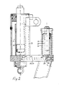
- lifting cylinder 7 is shown and the pertaining cylinder housing 17 and piston 18. There is also a storage vessel or sump 19.
- the cylinders 7 and 8 are interconnected via the valve housing 9 and comprises two channels 20 and 21 (see also Fig. 3) and connecting borings 22, 23, 24 and 25.
- the valve housing 9 is shown more clearly in Fig. 3 which is a plan view of the valve housing. From this figure it appears that the channel 20 interconnects the borings 22 and 24 and the channel 21 interconnects borings 23 and 25.
- the lifting cylinder 7, the pump cylinder 8 and the sump 19 are shown as circles with broken lines in Fig. 3. From Fig. 3 it appears that both borings 22 and 23 open to the pump cylinder.
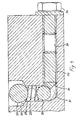
- Another channel 30 is shown in Fig. 3 and opens to the boring 22 as shown in more details i Fig. 4.
- the ball 28 is shown resting on its spring 29.
- the lower portion of the spring rested directly on the bottom 31 of the boring 22, which was the reason for the above-mentioned problems.
- the channel 30 is provided with windings for a screw 32.
- the lower portion of the spring 29 (the spring is here shorter) rests on another ball 33.
- the inner end of the screw 32 is provided with a conical portion 34 cooperating with the ball 33 as appears from Fig. 4. If the screw is moved to the left in Fig. 4, the ball 33 will rise and it will be required a greater force for bringing the ball 28 to abutment to its seat 35. The other way around, it the screw is moved to the right in Fig. 4, the ball 33 will be lowered, which means that less force is required for bringing the ball 28 to abutment to its seat 35. The idle operation is thus influenced upon by the adjustment of the screw 32.
- the screw 32 in Fig. 4 is shown enclosed in the channel 30 which is sealed at its end by a screw 36.
- the screw 36 is removed, whereupon a insex key is inserted in the screw 32 and the screw is moved to a position which gives the desired idle operation.
Landscapes
- Engineering & Computer Science (AREA)
- Chemical & Material Sciences (AREA)
- Combustion & Propulsion (AREA)
- Transportation (AREA)
- Mechanical Engineering (AREA)
- Forklifts And Lifting Vehicles (AREA)
- Handcart (AREA)
- Safety Valves (AREA)
- Lift Valve (AREA)
Applications Claiming Priority (2)
| Application Number | Priority Date | Filing Date | Title |
|---|---|---|---|
| SE8803670 | 1988-10-14 | ||
| SE8803670A SE462843B (sv) | 1988-10-14 | 1988-10-14 | Instaellningsanordning foer en frigaangsventil i en gaffellyftvagn |
Publications (2)
| Publication Number | Publication Date |
|---|---|
| EP0363951A2 true EP0363951A2 (fr) | 1990-04-18 |
| EP0363951A3 EP0363951A3 (fr) | 1990-12-19 |
Family
ID=20373635
Family Applications (1)
| Application Number | Title | Priority Date | Filing Date |
|---|---|---|---|
| EP19890118961 Withdrawn EP0363951A3 (fr) | 1988-10-14 | 1989-10-12 | Vérin pour chariot à fourche |
Country Status (5)
| Country | Link |
|---|---|
| EP (1) | EP0363951A3 (fr) |
| DK (1) | DK510789A (fr) |
| FI (1) | FI88494C (fr) |
| NO (1) | NO171447C (fr) |
| SE (1) | SE462843B (fr) |
Cited By (1)
| Publication number | Priority date | Publication date | Assignee | Title |
|---|---|---|---|---|
| CN105799755A (zh) * | 2016-03-29 | 2016-07-27 | 陈善兰 | 一种矩形板材用自动卸料式运输装置 |
Families Citing this family (1)
| Publication number | Priority date | Publication date | Assignee | Title |
|---|---|---|---|---|
| CN104817043B (zh) * | 2015-04-09 | 2017-01-25 | 山东建筑大学 | 手动液压叉车节流缓降缸 |
Family Cites Families (3)
| Publication number | Priority date | Publication date | Assignee | Title |
|---|---|---|---|---|
| US3018786A (en) * | 1959-01-23 | 1962-01-30 | James L Stratton | Safety brake valve |
| US3122381A (en) * | 1960-08-16 | 1964-02-25 | Jonard Ind Inc | Hydraulic lift truck |
| US4497501A (en) * | 1981-10-26 | 1985-02-05 | Equipment Company Of America | Pallet truck with hydraulic lift |
-
1988
- 1988-10-14 SE SE8803670A patent/SE462843B/sv not_active IP Right Cessation
-
1989
- 1989-10-12 EP EP19890118961 patent/EP0363951A3/fr not_active Withdrawn
- 1989-10-13 DK DK510789A patent/DK510789A/da not_active Application Discontinuation
- 1989-10-13 FI FI894872A patent/FI88494C/fi not_active IP Right Cessation
- 1989-10-13 NO NO894105A patent/NO171447C/no unknown
Cited By (2)
| Publication number | Priority date | Publication date | Assignee | Title |
|---|---|---|---|---|
| CN105799755A (zh) * | 2016-03-29 | 2016-07-27 | 陈善兰 | 一种矩形板材用自动卸料式运输装置 |
| CN105799755B (zh) * | 2016-03-29 | 2018-07-10 | 久耀电子科技(江苏)有限公司 | 一种矩形板材用自动卸料式运输装置 |
Also Published As
| Publication number | Publication date |
|---|---|
| SE8803670L (sv) | 1990-04-15 |
| DK510789A (da) | 1990-04-15 |
| NO894105D0 (no) | 1989-10-13 |
| FI88494B (fi) | 1993-02-15 |
| SE462843B (sv) | 1990-09-10 |
| EP0363951A3 (fr) | 1990-12-19 |
| NO894105L (no) | 1990-04-17 |
| NO171447B (no) | 1992-12-07 |
| DK510789D0 (da) | 1989-10-13 |
| FI894872A0 (fi) | 1989-10-13 |
| FI88494C (fi) | 1993-05-25 |
| SE8803670D0 (sv) | 1988-10-14 |
| NO171447C (no) | 1993-03-17 |
Similar Documents
| Publication | Publication Date | Title |
|---|---|---|
| US4750579A (en) | Arrangement in industrial trucks | |
| US4244275A (en) | Counterbalance valve | |
| US4223693A (en) | Counterbalance valve | |
| US4886244A (en) | Hydraulic lift perfected for the lifting and the handling of heavy loads of several tons | |
| US4338856A (en) | Dual pilot counterbalance valve | |
| JPH0616957B2 (ja) | 圧縮成形機におけるラムの昇降機構 | |
| US3782249A (en) | Hydraulic control system with locking valve to prevent accidental or unauthorized lowering of a tractor implement | |
| US6622485B2 (en) | Manually operated zero-load rapid lifting hydraulic jack | |
| US3449910A (en) | Hydraulic force exerting apparatus | |
| FI88494B (fi) | Instaellningsanordning foer frigaongsventil i gaffellyftvagn | |
| US3687417A (en) | Automatic cushioning valve | |
| US4834339A (en) | Hydraulic jack system | |
| JP2711750B2 (ja) | フォークリフトトラック | |
| US5038669A (en) | RAM piston with internal reservoir and check valve | |
| JP2858168B2 (ja) | リフト運搬台車等の昇降用油圧装置 | |
| US4359205A (en) | Hydraulically operated lifting apparatus and pump therefor | |
| JPH06286984A (ja) | 油圧ジャッキ | |
| JPH0636075Y2 (ja) | リフト装置 | |
| JPH0435356Y2 (fr) | ||
| SU1314150A1 (ru) | Гидросистема управлени подъемом вилочного погрузчика | |
| US4105087A (en) | Hydraulic cab tilting systems | |
| US4612846A (en) | High pressure hydraulic distributor having a mechanically controlled discharge valve | |
| JP2585899B2 (ja) | 車輌整備用リフトのシリンダ機構における同調ズレの修正方法 | |
| SU1184795A1 (ru) | Подъемник гидравлический | |
| JP3240802B2 (ja) | オーダーピッカーの昇降速度調整装置 |
Legal Events
| Date | Code | Title | Description |
|---|---|---|---|
| PUAI | Public reference made under article 153(3) epc to a published international application that has entered the european phase |
Free format text: ORIGINAL CODE: 0009012 |
|
| AK | Designated contracting states |
Kind code of ref document: A2 Designated state(s): AT BE CH DE ES FR GB GR IT LI LU NL SE |
|
| PUAL | Search report despatched |
Free format text: ORIGINAL CODE: 0009013 |
|
| AK | Designated contracting states |
Kind code of ref document: A3 Designated state(s): AT BE CH DE ES FR GB GR IT LI LU NL SE |
|
| 17P | Request for examination filed |
Effective date: 19910615 |
|
| 17Q | First examination report despatched |
Effective date: 19920708 |
|
| STAA | Information on the status of an ep patent application or granted ep patent |
Free format text: STATUS: THE APPLICATION IS DEEMED TO BE WITHDRAWN |
|
| 18D | Application deemed to be withdrawn |
Effective date: 19931207 |