EP0364252A2 - Abrasionsprüfgeräte - Google Patents
Abrasionsprüfgeräte Download PDFInfo
- Publication number
- EP0364252A2 EP0364252A2 EP89310420A EP89310420A EP0364252A2 EP 0364252 A2 EP0364252 A2 EP 0364252A2 EP 89310420 A EP89310420 A EP 89310420A EP 89310420 A EP89310420 A EP 89310420A EP 0364252 A2 EP0364252 A2 EP 0364252A2
- Authority
- EP
- European Patent Office
- Prior art keywords
- testpiece
- type
- pin
- disk type
- pin type
- Prior art date
- Legal status (The legal status is an assumption and is not a legal conclusion. Google has not performed a legal analysis and makes no representation as to the accuracy of the status listed.)
- Granted
Links
- 238000012360 testing method Methods 0.000 title claims abstract description 36
- 238000006073 displacement reaction Methods 0.000 claims abstract description 40
- 238000005259 measurement Methods 0.000 description 12
- 238000000034 method Methods 0.000 description 9
- 239000000463 material Substances 0.000 description 3
- 230000000750 progressive effect Effects 0.000 description 2
- 229930182556 Polyacetal Natural products 0.000 description 1
- 230000002844 continuous effect Effects 0.000 description 1
- 230000000694 effects Effects 0.000 description 1
- 230000020169 heat generation Effects 0.000 description 1
- 238000002347 injection Methods 0.000 description 1
- 239000007924 injection Substances 0.000 description 1
- 208000020442 loss of weight Diseases 0.000 description 1
- 238000012986 modification Methods 0.000 description 1
- 230000004048 modification Effects 0.000 description 1
- 229920006324 polyoxymethylene Polymers 0.000 description 1
- 229910001220 stainless steel Inorganic materials 0.000 description 1
- 239000010935 stainless steel Substances 0.000 description 1
- 230000003746 surface roughness Effects 0.000 description 1
- 208000016261 weight loss Diseases 0.000 description 1
- 230000004580 weight loss Effects 0.000 description 1
Images
Classifications
-
- G—PHYSICS
- G01—MEASURING; TESTING
- G01N—INVESTIGATING OR ANALYSING MATERIALS BY DETERMINING THEIR CHEMICAL OR PHYSICAL PROPERTIES
- G01N3/00—Investigating strength properties of solid materials by application of mechanical stress
- G01N3/56—Investigating resistance to wear or abrasion
Definitions
- the present invention relates to a wear testing device used for measuring the amount of wear of a sliding material, and more particularly, to a pin-on-disk type wear testing device in which a pin type testpiece is in contact with a rotating disk under a constant load for measuring the amount of wear of the pin type testpiece.
- a pin-on-disk type wear testing device As a wear testing device for measuring the amount of wear of a sliding material, a pin-on-disk type wear testing device is known in which a pin type testpiece to be measured for wear is stationarily in contact with a rotating disk type testpiece for measuring the rate of wear of the pin type testpiece with respect to time.
- Method "A” in which the rate of weight loss from the pin type testpiece which slides against the rotating disk type testpiece is measured with respect to time to calculate the rate of wear with respect to time
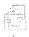
- Method "B" as shown in Fig.
- a rotating disk type testpiece 13 is mounted on a disk type testpiece table 12 that is supported in a base 11 to which a contact or non-contact type displacement gauge 18 is fixed for detecting the progressive amount of displacement between the base 11 and a pin type testpiece 14 in contact with the disk type testpiece 13 under a constant load, and the amount of wear of the pin type testpiece 14 is measured by the amount of displacement.
- method “B” allows continuous measurement of the wear rate of the pin type testpiece with respect to time.
- the amount of displacement measured by the displacement gauge 18 represents the absolute displacement with respect to the base 11 .
- the amount of displacement measured by the displacement gauge 18 includes not only the wear loss ⁇ h of the pin type testpiece but also the error ⁇ h′ caused by the displacement of the disk type testpiece with respect to the base 11 .
- the cause of the error ⁇ h′ includes the displacement caused by an axial positional change of the disk type testpiece 13 due to its rotational motion, a circumferential waving motion of the disk type testpiece 13 , and the thermal expansion of whole device due to thermal changes such as heat generation through the friction between the pin type testpiece and the disk type testpiece, all of which combine to prevent accurate measurement of the wear rate of the pin type testpiece 14 with respect to time.
- a pin-on-disk type wear testing device embodying this invention is a pin-on-disk type wear testing device in which a pin type testpiece is stationarily in contact with a rotating disk type testpiece under a constant load, the pin type testpiece sliding against the disk type testpiece along a given circular track thereon, to measure the wear rate of the pin type testpiece with respect to time
- the pin-on-disk type wear testing device comprising: a pin type testpiece holder for holding the pin type testpiece in such a way as to move integrally therewith; and a non-contact type displacement gauge fixed to the pin type testpiece holder in such a way as to face the disk type testpiece, for detecting the relative displacement of the pin type testpiece holder with respect to the disk type testpiece.
- the non-contact type displacement gauge is so mounted as to face a position adjacent to a position where the pin type testpiece is sliding against the disk type testpiece along the circular track thereon, for detecting the relative displacement of the facing position on the disk type testpiece with respect to the pin type testpiece holder.
- the disk type testpiece is rotated integrally with a disk type testpiece table which is rotatably supported in a base.
- an embodiment of the invention can provide a pin-on-disk type wear testing device which has a non-contact type displacement gauge that moves integrally with the pin type testpiece sliding against the disk type testpiece, so that the device can accurately measure the displacement of the pin type testpiece with respect to the disk type testpiece without being affected by waving motion of the disk type testpiece or by thermal expansion of parts of the whole device, thus making it possible to measure the amount of wear of the pin type testpiece with desirably improved accuracy.
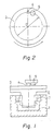
- Fig. 1 shows a pin-on-disk type wear testing device embodying the invention, which includes a testpiece table 2 rotatably supported in a base 1 by means of a ball bearing 7 .
- the testpiece table 2 has an approximately planar top surface on which a disk type testpiece 3 is mounted for integral rotation therewith.
- a pin type testpiece 4 is stationarily in contact with the rotating disk under a constant load at a position away from the rotational center thereof by a given length, the pin type testpiece 4 sliding against the disk type testpiece 3 along a circular track of a given diameter D by the rotation of the disk type member 3 .
- the pin type testpiece 4 is fixed to a pin type testpiece holder 6 which is disposed stationarily with respect to the rotating disk type testpiece 3 , the pin type testpiece holder 6 moving integrally with the pin type testpiece 4 in the vertical direction to follow the vertical movement of the pin type testpiece 4 .
- the non-contact type displacement gauge 5 is so mounted as to face a position adjacent to a position where the pin type testpiece 4 slides against the disk type test-piece 3 along the circular track thereon, for measuring the relative displacement of the facing position on the disk type testpiece 3 with respect to the pin type testpiece holder 6 .
- the amount of wear of the pin type testpiece 4 is measured with respect to time on the basis of the measurement by the non-contact type displacement gauge 5 .
- the pin type testpiece 4 is stationarily in contact with the rotating disk type testpiece 3 under a constant load for sliding along the specified circular track thereon, thus generating progressive wear of the pin type testpiece 4 .
- the non-contact type displacement gauge 5 is mounted to the pin type testpiece holder 6 , to which the pin type testpiece 4 is fixed, to continuously measure the displacement of the pin type testpiece holder 6 with respect to the position adjacent to the position where the pin type testpiece 4 is sliding against the disk type testpiece 3 along the circular track thereon, and the displacement measured by the displacement gauge 5 with respect to time is measured as the rate of wear of the pin type testpiece 4 with respect to time.
- the non-contact type displacement gauge 5 is fixed to the pin type testpiece holder 6 which moves integrally with the pin type testpiece 4 to follow the vertical movement thereof, if the disk type testpiece 3 exhibits a waving motion in its circumferential direction, the displacement gauge 5 is prevented from being affected by the waving motion of the disk type testpiece 3 , the pin type testpiece 4 moving to follow the waving motion thereof and therefore the pin type testpiece holder 6 moving to follow the movement of the pin type testpiece 4 . Also, if the whole device is deformed due to thermal expansion, the displacement of the disk type testpiece 3 due to the deformation is prevented from being measured by the displacement gauge 5 .
- the pin-on-disk type wear testing device of Figure 1 is capable of accurately measuring the wear rate of the pin type testpiece 4 .
- PTFE polytetrafluoroethylen
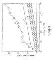
- the diameter of the circular track along which the pin type testpiece was to slide against the disk type testpiece was determined at 85 mm, the contact pressure between the pin type testpiece and the disk type testpiece at 0.3 MPa, the sliding speed of the pin type testpiece (the rotating speed of the disk type testpiece) at 0.5 m/s, and the test temperature at 23°C, and the amount of wear of the pin type testpiece was measured by the above described pin-on-disk type wear testing device of Figure 1. The results are shown in the graph of Fig. 4 as wear progress curve I .
- the wear progress curve I for the pin type testpiece measured by the wear testing device of Figure 1 shows a stable progress with respect to time, indicating accurate measurement of the amount of wear of the pin type testpiece.
- Method "A” since the weight of the pin type testpiece is measured when the pin type testpiece dismounted from the wear testing device, and then the pin type testpiece is refitted to the wear testing device, the position at which the pin type testpiece slides against the disk type testpiece changes, the effect being shown in the measurement.
- Method “B” is susceptible to the error caused by such factors as axial motion of the disk type testpiece and thermal expansion of the whole device, and in some cases, causes a phenomenon in which a negative value is given as the wear value in the early stage of the wear. Furthermore, the circumferential waving motion of the disk type testpiece affects the measurement, causing the wear progress curve to greatly fluctuate so as to hamper accurate measurement.
- a pin-on-disk type wear testing device embodying the invention is capable of providing highly reliable measurement.
Landscapes
- Physics & Mathematics (AREA)
- Health & Medical Sciences (AREA)
- Life Sciences & Earth Sciences (AREA)
- Chemical & Material Sciences (AREA)
- Analytical Chemistry (AREA)
- Biochemistry (AREA)
- General Health & Medical Sciences (AREA)
- General Physics & Mathematics (AREA)
- Immunology (AREA)
- Pathology (AREA)
- Length Measuring Devices With Unspecified Measuring Means (AREA)
- Measurement Of Length, Angles, Or The Like Using Electric Or Magnetic Means (AREA)
- Length Measuring Devices By Optical Means (AREA)
Applications Claiming Priority (2)
| Application Number | Priority Date | Filing Date | Title |
|---|---|---|---|
| JP256335/88 | 1988-10-11 | ||
| JP63256335A JPH02102433A (ja) | 1988-10-11 | 1988-10-11 | ピン−ディスク型摩耗試験装置 |
Publications (3)
| Publication Number | Publication Date |
|---|---|
| EP0364252A2 true EP0364252A2 (de) | 1990-04-18 |
| EP0364252A3 EP0364252A3 (de) | 1991-01-30 |
| EP0364252B1 EP0364252B1 (de) | 1994-04-27 |
Family
ID=17291243
Family Applications (1)
| Application Number | Title | Priority Date | Filing Date |
|---|---|---|---|
| EP89310420A Expired - Lifetime EP0364252B1 (de) | 1988-10-11 | 1989-10-11 | Abrasionsprüfgeräte |
Country Status (4)
| Country | Link |
|---|---|
| US (1) | US4966030A (de) |
| EP (1) | EP0364252B1 (de) |
| JP (1) | JPH02102433A (de) |
| DE (1) | DE68914933T2 (de) |
Cited By (3)
| Publication number | Priority date | Publication date | Assignee | Title |
|---|---|---|---|---|
| RU2130602C1 (ru) * | 1997-08-18 | 1999-05-20 | Казаков Владимир Михайлович | Способ получения результатов экспериментальных исследований поверхности цилиндра |
| RU2164346C2 (ru) * | 1999-06-25 | 2001-03-20 | Казаков Владимир Михайлович | Способ получения результатов экспериментальных исследований поверхности шеек коленвала и вкладышей |
| RU2182323C2 (ru) * | 2000-02-08 | 2002-05-10 | Казаков Владимир Михайлович | Способ исследования влияния процесса обработки шеек коленвалов двигателя внутреннего сгорания в процессе натурных испытаний двигателя |
Families Citing this family (13)
| Publication number | Priority date | Publication date | Assignee | Title |
|---|---|---|---|---|
| JP2964654B2 (ja) * | 1991-01-30 | 1999-10-18 | 住友電気工業株式会社 | 摩耗評価試験方法 |
| US5795990A (en) * | 1997-07-30 | 1998-08-18 | Center For Tribology, Inc. | Method and apparatus for measuring friction and wear characteristics of materials |
| US6840082B2 (en) * | 2001-11-30 | 2005-01-11 | Paul R. Evans | Machine for testing wear, wear-preventative and friction properties of lubricants and other materials |
| JP4213913B2 (ja) * | 2002-07-01 | 2009-01-28 | Tdk株式会社 | 光記録媒体についての摩擦特性測定方法、および光記録媒体用の摩擦特性測定装置 |
| US20040226350A1 (en) * | 2003-03-17 | 2004-11-18 | Kim Jin Hong | Apparatus and method for testing endurance of optical disc |
| KR100947230B1 (ko) * | 2003-09-16 | 2010-03-11 | 엘지전자 주식회사 | 광디스크 표면의 기계적 내구성 검사 장치 및 방법 |
| US20050276532A1 (en) * | 2004-06-14 | 2005-12-15 | Zbigniew Zurecki | Rolling ball tribometer |
| SG127774A1 (en) * | 2005-06-02 | 2006-12-29 | Sony Corp | Method and apparatus for measuring a surface property |
| WO2012006613A2 (en) * | 2010-07-09 | 2012-01-12 | Tribis Engineering, Inc. | Tribometer |
| DE202011105181U1 (de) | 2011-08-29 | 2011-12-22 | Waltraud Brandl | Prüfstand für die Untersuchung des Verschleißverhaltens an Zylinder-Innenflächen |
| CN104515714A (zh) * | 2015-01-07 | 2015-04-15 | 北京林业大学 | 一种高速高温液压可调载的刀-屑摩擦装置及摩擦测量方法 |
| CN109690282B (zh) | 2016-09-14 | 2024-01-09 | 罗地亚经营管理公司 | 用于测量橡胶磨损的装置 |
| CN107290237A (zh) * | 2017-06-21 | 2017-10-24 | 南京理工大学 | 一种用于测量圆柱试样外圆周向耐磨性能的装置 |
Family Cites Families (1)
| Publication number | Priority date | Publication date | Assignee | Title |
|---|---|---|---|---|
| BE425176A (de) * | 1937-12-04 |
-
1988
- 1988-10-11 JP JP63256335A patent/JPH02102433A/ja active Pending
-
1989
- 1989-10-05 US US07/417,642 patent/US4966030A/en not_active Expired - Lifetime
- 1989-10-11 DE DE68914933T patent/DE68914933T2/de not_active Expired - Fee Related
- 1989-10-11 EP EP89310420A patent/EP0364252B1/de not_active Expired - Lifetime
Cited By (3)
| Publication number | Priority date | Publication date | Assignee | Title |
|---|---|---|---|---|
| RU2130602C1 (ru) * | 1997-08-18 | 1999-05-20 | Казаков Владимир Михайлович | Способ получения результатов экспериментальных исследований поверхности цилиндра |
| RU2164346C2 (ru) * | 1999-06-25 | 2001-03-20 | Казаков Владимир Михайлович | Способ получения результатов экспериментальных исследований поверхности шеек коленвала и вкладышей |
| RU2182323C2 (ru) * | 2000-02-08 | 2002-05-10 | Казаков Владимир Михайлович | Способ исследования влияния процесса обработки шеек коленвалов двигателя внутреннего сгорания в процессе натурных испытаний двигателя |
Also Published As
| Publication number | Publication date |
|---|---|
| EP0364252A3 (de) | 1991-01-30 |
| DE68914933D1 (de) | 1994-06-01 |
| EP0364252B1 (de) | 1994-04-27 |
| DE68914933T2 (de) | 1994-08-11 |
| US4966030A (en) | 1990-10-30 |
| JPH02102433A (ja) | 1990-04-16 |
Similar Documents
| Publication | Publication Date | Title |
|---|---|---|
| EP0364252A2 (de) | Abrasionsprüfgeräte | |
| US5131166A (en) | Vertical/horizontal measuring apparatus and procedure for its use | |
| EP0358656B1 (de) | Präzisions-gleitführungsbahnen | |
| EP1180662B1 (de) | Positionsgeber | |
| JP2004069510A (ja) | デジタル測定ヘッド | |
| JPS5512406A (en) | Method of compensating error in measuring circle or arc and meter with compensator | |
| US5207005A (en) | Floating head probe | |
| US2785474A (en) | Precision spherical surface gauge | |
| JP2572918B2 (ja) | スピンドルを有するリニア測定器および測定方法 | |
| US3307265A (en) | Distance measuring by friction wheel instruments | |
| JP2539461B2 (ja) | 真直度計 | |
| US4475291A (en) | Blade orientation gauge | |
| FI94908C (fi) | Laite kappaleiden muodon ja/tai muotovirheiden mittaamiseksi | |
| JPS63173908A (ja) | 段差測定装置 | |
| SU1698699A1 (ru) | Способ испытани на изнашивание покрытий, имеющих переменные физико-механические свойства по глубине | |
| SU1679173A2 (ru) | Контактный толщиномер движущегос материала, преимущественно металлической ленты | |
| US7107695B2 (en) | Device and process for profile measurement | |
| JPH04273040A (ja) | ブロックオンリング型摩耗試験装置 | |
| CN222166079U (zh) | 一种纸管同轴旋转特性测定仪 | |
| Reason | Stylus methods of surface measurement | |
| SU1562761A1 (ru) | Устройство дл исследовани изнашивани полимерных материалов | |
| JPS5870101A (ja) | 曲率半径測定装置 | |
| SU1444615A1 (ru) | Способ контрол расположени поверхностей сферических колец подшипников | |
| SU1092386A1 (ru) | Способ определени коэффициента трени твердых материалов | |
| SU1219914A1 (ru) | Способ определени зазора винтового механизма задатчика и устройство дл его осуществлени |
Legal Events
| Date | Code | Title | Description |
|---|---|---|---|
| PUAI | Public reference made under article 153(3) epc to a published international application that has entered the european phase |
Free format text: ORIGINAL CODE: 0009012 |
|
| AK | Designated contracting states |
Kind code of ref document: A2 Designated state(s): DE FR GB |
|
| PUAL | Search report despatched |
Free format text: ORIGINAL CODE: 0009013 |
|
| AK | Designated contracting states |
Kind code of ref document: A3 Designated state(s): DE FR GB |
|
| 17P | Request for examination filed |
Effective date: 19910425 |
|
| 17Q | First examination report despatched |
Effective date: 19921208 |
|
| GRAA | (expected) grant |
Free format text: ORIGINAL CODE: 0009210 |
|
| AK | Designated contracting states |
Kind code of ref document: B1 Designated state(s): DE FR GB |
|
| REF | Corresponds to: |
Ref document number: 68914933 Country of ref document: DE Date of ref document: 19940601 |
|
| ET | Fr: translation filed | ||
| PLBE | No opposition filed within time limit |
Free format text: ORIGINAL CODE: 0009261 |
|
| STAA | Information on the status of an ep patent application or granted ep patent |
Free format text: STATUS: NO OPPOSITION FILED WITHIN TIME LIMIT |
|
| 26N | No opposition filed | ||
| PGFP | Annual fee paid to national office [announced via postgrant information from national office to epo] |
Ref country code: FR Payment date: 19981015 Year of fee payment: 10 |
|
| PGFP | Annual fee paid to national office [announced via postgrant information from national office to epo] |
Ref country code: GB Payment date: 19981023 Year of fee payment: 10 Ref country code: DE Payment date: 19981023 Year of fee payment: 10 |
|
| PG25 | Lapsed in a contracting state [announced via postgrant information from national office to epo] |
Ref country code: GB Free format text: LAPSE BECAUSE OF NON-PAYMENT OF DUE FEES Effective date: 19991011 |
|
| GBPC | Gb: european patent ceased through non-payment of renewal fee |
Effective date: 19991011 |
|
| PG25 | Lapsed in a contracting state [announced via postgrant information from national office to epo] |
Ref country code: FR Free format text: LAPSE BECAUSE OF NON-PAYMENT OF DUE FEES Effective date: 20000630 |
|
| PG25 | Lapsed in a contracting state [announced via postgrant information from national office to epo] |
Ref country code: DE Free format text: LAPSE BECAUSE OF NON-PAYMENT OF DUE FEES Effective date: 20000801 |
|
| REG | Reference to a national code |
Ref country code: FR Ref legal event code: ST |