EP0364276B1 - Dispositif pour commander des transmissions et des embrayages de véhicules - Google Patents
Dispositif pour commander des transmissions et des embrayages de véhicules Download PDFInfo
- Publication number
- EP0364276B1 EP0364276B1 EP89310484A EP89310484A EP0364276B1 EP 0364276 B1 EP0364276 B1 EP 0364276B1 EP 89310484 A EP89310484 A EP 89310484A EP 89310484 A EP89310484 A EP 89310484A EP 0364276 B1 EP0364276 B1 EP 0364276B1
- Authority
- EP
- European Patent Office
- Prior art keywords
- gear
- clutch
- input
- vehicle
- engaging
- Prior art date
- Legal status (The legal status is an assumption and is not a legal conclusion. Google has not performed a legal analysis and makes no representation as to the accuracy of the status listed.)
- Expired - Lifetime
Links
Images


Classifications
-
- B—PERFORMING OPERATIONS; TRANSPORTING
- B60—VEHICLES IN GENERAL
- B60W—CONJOINT CONTROL OF VEHICLE SUB-UNITS OF DIFFERENT TYPE OR DIFFERENT FUNCTION; CONTROL SYSTEMS SPECIALLY ADAPTED FOR HYBRID VEHICLES; ROAD VEHICLE DRIVE CONTROL SYSTEMS FOR PURPOSES NOT RELATED TO THE CONTROL OF A PARTICULAR SUB-UNIT
- B60W10/00—Conjoint control of vehicle sub-units of different type or different function
- B60W10/04—Conjoint control of vehicle sub-units of different type or different function including control of propulsion units
- B60W10/06—Conjoint control of vehicle sub-units of different type or different function including control of propulsion units including control of combustion engines
-
- B—PERFORMING OPERATIONS; TRANSPORTING
- B60—VEHICLES IN GENERAL
- B60W—CONJOINT CONTROL OF VEHICLE SUB-UNITS OF DIFFERENT TYPE OR DIFFERENT FUNCTION; CONTROL SYSTEMS SPECIALLY ADAPTED FOR HYBRID VEHICLES; ROAD VEHICLE DRIVE CONTROL SYSTEMS FOR PURPOSES NOT RELATED TO THE CONTROL OF A PARTICULAR SUB-UNIT
- B60W10/00—Conjoint control of vehicle sub-units of different type or different function
- B60W10/10—Conjoint control of vehicle sub-units of different type or different function including control of change-speed gearings
- B60W10/11—Stepped gearings
-
- B—PERFORMING OPERATIONS; TRANSPORTING
- B60—VEHICLES IN GENERAL
- B60W—CONJOINT CONTROL OF VEHICLE SUB-UNITS OF DIFFERENT TYPE OR DIFFERENT FUNCTION; CONTROL SYSTEMS SPECIALLY ADAPTED FOR HYBRID VEHICLES; ROAD VEHICLE DRIVE CONTROL SYSTEMS FOR PURPOSES NOT RELATED TO THE CONTROL OF A PARTICULAR SUB-UNIT
- B60W30/00—Purposes of road vehicle drive control systems not related to the control of a particular sub-unit, e.g. of systems using conjoint control of vehicle sub-units
- B60W30/18—Propelling the vehicle
-
- B—PERFORMING OPERATIONS; TRANSPORTING
- B60—VEHICLES IN GENERAL
- B60W—CONJOINT CONTROL OF VEHICLE SUB-UNITS OF DIFFERENT TYPE OR DIFFERENT FUNCTION; CONTROL SYSTEMS SPECIALLY ADAPTED FOR HYBRID VEHICLES; ROAD VEHICLE DRIVE CONTROL SYSTEMS FOR PURPOSES NOT RELATED TO THE CONTROL OF A PARTICULAR SUB-UNIT
- B60W2510/00—Input parameters relating to a particular sub-units
- B60W2510/02—Clutches
- B60W2510/0241—Clutch slip, i.e. difference between input and output speeds
-
- F—MECHANICAL ENGINEERING; LIGHTING; HEATING; WEAPONS; BLASTING
- F16—ENGINEERING ELEMENTS AND UNITS; GENERAL MEASURES FOR PRODUCING AND MAINTAINING EFFECTIVE FUNCTIONING OF MACHINES OR INSTALLATIONS; THERMAL INSULATION IN GENERAL
- F16H—GEARING
- F16H2312/00—Driving activities
- F16H2312/02—Driving off
-
- F—MECHANICAL ENGINEERING; LIGHTING; HEATING; WEAPONS; BLASTING
- F16—ENGINEERING ELEMENTS AND UNITS; GENERAL MEASURES FOR PRODUCING AND MAINTAINING EFFECTIVE FUNCTIONING OF MACHINES OR INSTALLATIONS; THERMAL INSULATION IN GENERAL
- F16H—GEARING
- F16H59/00—Control inputs to control units of change-speed- or reversing-gearings for conveying rotary motion
- F16H59/14—Inputs being a function of torque or torque demand
-
- F—MECHANICAL ENGINEERING; LIGHTING; HEATING; WEAPONS; BLASTING
- F16—ENGINEERING ELEMENTS AND UNITS; GENERAL MEASURES FOR PRODUCING AND MAINTAINING EFFECTIVE FUNCTIONING OF MACHINES OR INSTALLATIONS; THERMAL INSULATION IN GENERAL
- F16H—GEARING
- F16H59/00—Control inputs to control units of change-speed- or reversing-gearings for conveying rotary motion
- F16H59/50—Inputs being a function of the status of the machine, e.g. position of doors or safety belts
- F16H59/52—Inputs being a function of the status of the machine, e.g. position of doors or safety belts dependent on the weight of the machine, e.g. change in weight resulting from passengers boarding a bus
Definitions
- the present invention relates to an apparatus for controlling the gear transmission and clutch of a vehicle taking into account the load condition of the vehicle so as to start the vehicle smoothly.
- Japanese Patent Application Public Disclosure No. 115732/86 discloses a control system which is provided with a switch which can be set according to the load condition of the truck to make the feeling at drive-off of the truck the same between the fully loaded condition and the no-load condition of the truck.
- Japanese Patent Application Public Disclosure No. 72922/88 discloses a control system which provided with a variable resistor which can be set according to the load condition at that time for the same purpose.
- the operation speed of the clutch in a semi-engaging zone is determined in accordance with the position of the switch, enabling operation of the switch to eliminate the difference in the feeling of vehicle drive-off between at the fully loaded condition and at the no-load condition.
- EP 0268686 discloses a device which selects an "optimum speed stage" for the starting of a vehicle having an automatic transmission.
- the speed stage is selected, when the transmission is in a "drive” position, according to the vehicle load and the load incline.
- An object of the present invention is to provide an improved apparatus for controlling the gear transmission and clutch of vehicles, which is capable of eliminating the disadvantages described above.
- Another object of the present invention is to provide a control apparatus for vehicles having a gear transmission and a clutch, which is capable of automatically controlling the gear transmission and the clutch for drive-off of the vehicle under various load conditions of the vehicle.
- a further object of the present invention is to provide a control apparatus for vehicles having a gear transmission and a clutch, which is capable of assuring suitable control conditions of the gear transmission and the clutch for drive-off of the vehicle under various load conditions of the vehicle.
- GB 2199628 discloses an apparatus for controlling a vehicle having an automatic gear shift control system for a gear transmission and an automatic clutch control system for a friction type clutch, the apparatus comprising: an input means; and a first determining means responsive to said input means for determining engagement characteristics for the clutch for vehicle drive off.
- the input means is for inputting information concerning a load condition of the vehicle
- the first determining means is for determining characteristic curves for engaging the clutch
- the apparatus further comprises: a gear discriminating means responsive to said input means for discriminating whether or not a gear position set in the gear transmission corresponds to a predetermined allowable gear position at the time of vehicle drive-off; and an engaging means responsive to said first determining means and said gear discriminating means for carrying out the operation for engaging the clutch during vehicle drive-off in accordance with the characteristic curve determined by the first determining means only when the gear of the transmission is shifted to an allowable gear position.
- the characteristics for engaging the clutch for drive-off of the vehicle is determined by the first determining means in response to the information concerning the load condition of the vehicle from the input means. In addition, it is discriminated in accordance with the information whether or not the transmission is shifted to an allowable gear position for drive-off of the vehicle.
- the operation for engaging the clutch to start the vehicle can be carried out automatically on the basis of the characteristics for engaging the clutch determined by the first determining means only when the actual gear position of the transmission is one of the allowable gear positions.
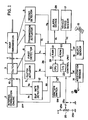
- Fig. 1 shows an embodiment of a vehicle control apparatus of the present invention having an automatic transmission system generally designated by reference numeral 1.
- the automatic transmission system 1 is used in a vehicle (not shown) powered by an internal combustion engine 2 and includes an automatic clutch control system for a friction type clutch 3 and an automatic gear shift control system for a gear transmission 4.
- a clutch actuator 5 is coupled with the clutch 3 and the operation for engaging/disengaging (ON/OFF) the clutch 3 is carried out by the clutch actuator 5 in response to a clutch control signal Sc produced by a control unit 6, which will be described in more detailed later.
- a transmission actuator 7 is coupled with the gear transmission 4 and the operation for shifting the gear transmission is carried out by the use of the transmission actuator in response to a transmission control signal St produced by the control unit 6.
- a first detector 8 coupled with the clutch 3 produces a first detection signal K1 showing the position of a pressure plate (not shown) of the clutch 3 manipulated by the clutch actuator 5, and a second detector 9 coupled with the gear transmission 4 produces a second detection signal K2 showing the actual gear position of the gear transmission 4 manipulated by the transmission actuator 7.
- the first and second detection signals K1 and K2 are input to the control unit 6.
- a first sensor 10 is provided on the input side of the clutch 3 for producing an input speed signal Sa showing the input rotational speed of the clutch 3 and a second sensor 11 is provided on the output side of the clutch 3 for producing an output speed signal Sb showing an output rotational speed of the clutch 3.
- the input and output speed signals Sa and Sb are supplied to the slip rate detector 12 for calculating a slip rate of the clutch 3 at each instant, and the slip rate signal SD representing the result of the calculation in the slip rate detector 12 is supplied from the slip rate detector 12 to the control unit 6.
- the control unit 6 further receives an acceleration signal AC showing the amount of operation of an accelerator pedal 13 from an acceleration sensor 14 and a selected position signal SP showing the position selected by a selector 15 from a select sensor 16.
- a vehicle speed sensor 17 produces a vehicle speed signal VC showing the speed of the vehicle and supplies it to the control unit 6.
- the control unit 6 also receives an ignition switch signal KY showing whether or not an ignition switch SW is in its OFF position.
- the control unit 6 has a central processing unit (CPU) 20, random access memory (RAM) 21, read-only memory (ROM) 22 and I/O interface 23, which are interconnected by a bus 24 to form a known-design microcomputer.
- CPU central processing unit
- RAM random access memory
- ROM read-only memory
- I/O interface 23 I/O interface 23
- the signals input to the control unit 6 are converted into digital from by the I/O interface 23 and the required control operations of the clutch 3 and the transmission 4 are carried out on the basis of the control program 30 in accordance with the signals input to the control unit 6.
- the vehicle control apparatus shown in Fig. 1 comprises an input device 25 for inputting information concerning the load condition of the vehicle, and an output signal Y produced by the input device 25 is supplied as a signal indicative of the load condition of the vehicle to the control unit 26.
- the input device 25 is constituted as a variable resistor having a pair of fixed terminals 25a and 25b, and a direct current voltage source +V with a constant voltage level V is applied across the fixed terminals 25a and 25b.
- the output voltage of the input device 25 is produced as an output signal Y from the movable terminal 25c of the variable resistor and applied to the control unit 26.
- the control unit 26 operates on the basis of a control program 60 stored in the ROM 22 for controlling the gear transmission 4 and the friction type clutch 3.
- Reference numeral 28 designates an alarm device.
- the input device 25 has an adjusting knob 27 secured on the rotating shaft (not shown) of the variable resistor and a mark 27a on the adjusting knob 27 can be positioned at any position between "O" position and "Max position.
- the position of the mark 27a will be referred to as the set position AP hereinafter.
- the region between "O” and “Max” is divided into three ranges: a small load range (O ⁇ AP ⁇ Min), a medium load range (Min ⁇ AP ⁇ C) and a large load range (C ⁇ AP ⁇ Max).
- Fig. 3 shows the relationship between the level of the output signal Y and the set position AP, in which the level of the output signal Y is dependent upon the set position AP.
- the level of the output signal Y varies linearly from +V to zero when the set position AP proceeds from “O" "Max”.
- an output signal Y of a level corresponding to the set position AP at that time is supplied to the control unit 26.
- the input device 25 may include a well-known mechanism for maintaining the set position AP thereof by a suitable force when the mark 27a is set at the "O" position.
- Fig. 4 is a flowchart showing the control program 60 executed in the control unit 6.
- step 61 digital data corresponding to the signals input to the control unit 26 are read in and stored in the RAM 21 in step 61. Then, the operation moves to step 62 wherein discrimination is made as to whether or not the ignition switch SW is in its OFF position. When the determination in step 62 is YES, the operation moves to step 63 wherein a control operation for halting the operation of the internal combustion engine 2 is executed. As a result, a halt signal STP is produced from the control unit 26 and is applied to the internal combustion engine 2, so that the rotation of the internal combustion engine 2 is halted. The operation returns to step 61 after the execution of step 63.
- step 62 When the ignition switch SW is in its ON or ST position, the determination in step 62 becomes NO and the operation moves to step 64, wherein discrimination is made as to whether or not the internal combustion engine 2 is rotating.
- step 64 When the engine 2 is not rotating, the determination in step 64 becomes NO and the operation moves to step 65 to execute the control operation for starting the engine 2. The operation returns to step 61 after the execution of step 65.
- step 64 when the engine 2 is rotating, the determination in step 64 becomes YES and the operation moves to step 66 wherein discrimination is made based on the second detection signal K2 as to whether or not the gear of the transmission 4 is in its neutral(N) position.
- step 66 When the determination in step 66 is YES, the operation returns to step 61.
- control operations are executed as follows.
- step 67 discrimination is made in accordance with the vehicle speed signal VC as to whether or not the vehicle speed is zero.
- the operation moves to step 74 when the vehicle speed is not zero.
- step 68 discrimination is made on the basis of the output signal Y as to whether or not the set position AP is within the small load range (O ⁇ AP ⁇ Min).
- the determination in step 68 is YES when the set position AP is in the small load range and the operation moves to step 69 wherein an alarm signal AL of low level is produced to put the alarm device 28 an inoperative state.
- step 70 discrimination is made on the basis of the output signal V as to whether or not the set position AP is within the medium load range (Min ⁇ AP ⁇ C).
- step 71 discrimination is made in step 71 as to whether or not the transmission 4 is in the 1st, 2nd or R gear position.
- the operation moves to step 69 when the determination in step 71 is YES.
- step 72 an alarm signal AL of high level is produced to put the alarm device 28 an operative state.
- the alarm device 28 may be an alarm lamp, an alarm buzzer or any other well-known suitable alarm apparatus, able to inform the driver that it has received the alarm signal of high level.
- step 70 becomes NO when the set position AP is set within the large load range, and then the operation moves to step 73 wherein discrimination is made as to whether or not the transmission 4 is in the 1st or R gear position.
- step 69 when the determination in step 73 is YES.
- step 72 is executed after the execution of step 73 when the determination in step 73 is NO.
- step 69 is executed only when a specific gear position is set for drive-off of the vehicle, and the alarm device 28 is rendered operative when a gear position other than the specific gear position is used for vehicle drive-off.
- the operation returns to step 62 without execution of the control operation for vehicle drive-off.
- the operation further moves to step 74 and the following control operations are carried out.
- step 74 Discrimination is made in step 74 as to whether or not the operations for vehicle drive-off have been completed.
- the determination in step 74 becomes YES and the control operation for running of the vehicle is carried out in step 75.
- the operation returns to step 61 after the execution of step 75.
- step 74 becomes NO when the operations for vehicle drive-off has not been completed, and the operation moves to step 76 wherein discrimination is made as to whether or not the amount ⁇ of operation of the accelerator pedal 13 is more than a predetermined magnitude ⁇ a.
- step 76 discrimination is made as to whether or not the amount ⁇ of operation of the accelerator pedal 13 is more than a predetermined magnitude ⁇ a.
- the determination in step 76 becomes NO.
- the operation moves to step 77 wherein the operations for stopping the vehicle are carried out, and returns to step 61 thereafter.
- step 76 When the amount ⁇ is more than ⁇ a, it is discriminated that the driver intends to start the vehicle and the determination in step 76 becomes YES. Thus, the operation moves to step 78 wherein the characteristic curve for engaging the clutch 3 is determined in accordance with the level of the output signal Y.
- the characteristic curve for engaging the clutch 3 for vehicle drive-off may be determined in such a way that, as shown in Fig. 5, the rate of movement of the pressure plate just after the start of the clutch engagement becomes larger with increase in the vehicle load set by the input device 25, whereby an excellent feeling at vehicle drive-off is assured regardless of the magnitude of the load of the vehicle and the clutch is reliably protected from rapid wear.
- the characteristic curve for engaging the clutch 3 may alternatively be determined so as to shift the basic characteristic curve shown by the solid line toward clutch ON by a value f(Y) corresponding to the level of the output signal Y to obtain the characteristic curve shown by the broken line in Fig. 10.
- the amount ⁇ of operation of the accelerator pedal 13 is plotted on the abscissa and the target position T of the pressure plate of the clutch 3 is plotted on the ordinate.
- a target characteristic curve is determined in accordance with the amount ⁇ of operation of the accelerator pedal 13 at that time.
- Fig. 11 is a flowchart showing a program for determining the characteristic map data for engaging the clutch 3 as described in conjunction with Fig. 10.
- the basic characteristic map data TS is determined in step 81.
- the map data corresponding to the basic characteristic curve shown in Fig. 10 is selected and stored in the RAM 21.
- the value f(Y) is calculated in step 82 on the basis of a predetermined function of the level of the output signal Y in accordance with the level of the output signal Y.
- the operation then moves to step 83, wherein the desired characteristic map data CTS is obtained by correcting the map data TS by the value f(Y).
- step 79 the control operation for vehicle drive-off is carried out. That is, under the condition that the transmission 4 has been shifted to the gear position determined, the clutch 3 is engaged in accordance with the characteristic curve determined in step 78.
- the clutch control signal Sc corresponds to the target position T determined on the basis of the characteristic map data CTS at each instant and the pressure plate of the clutch 3 is positioned by the clutch actuator 5 to the location indicated by the clutch control signal Sc.
- the operation returns to step 61 after the execution of step 79.
- step 74 becomes YES when these control operations for vehicle drive-off have been completed, and the operation moves to step 75 wherein the control operations for vehicle running are carried out.
- the output signal Y with the level corresponding to the set position AP is applied to the control unit 26, and it is discriminated on the basis of the output signal Y whether or not the actual set gear position for vehicle drive-off is an allowable gear position.
- the load condition of the vehicle is divided into the three ranges and the specific allowable gear positions are determined for each range.
- the control operations for vehicle drive-off are carried out when the set gear position corresponds to the allowable position for the load condition set by the input device 25 at that time.
- the alarm device 28 is rendered operative without performance of the control operations for vehicle drive-off when the set gear position dose not corresponds to an allowable position for the load condition set by the input device 25 at that time.
- the characteristic curve for engaging the clutch for vehicle drive-off is determined in accordance with the set position AP in such a way that a feeling of clutch slipping is not experienced even under heavy load condition, so that the life of the clutch becomes long.
Landscapes
- Engineering & Computer Science (AREA)
- Chemical & Material Sciences (AREA)
- Combustion & Propulsion (AREA)
- Transportation (AREA)
- Mechanical Engineering (AREA)
- Automation & Control Theory (AREA)
- Control Of Transmission Device (AREA)
- Control Of Driving Devices And Active Controlling Of Vehicle (AREA)
Claims (7)
- Dispositif pour commander un véhicule comportant un système de commande automatique de changement de vitesse pour une transmission à engrenage et un système de commande automatique d'embrayage pour un embrayage du type à friction, ledit dispositif comportant :
un moyen d'entrée (25) et
un premier moyen de détermination (26) sensible audit moyen d'entrée pour établir les caractéristiques de mise en prise de l'embrayage (31) au démarrage du véhicule, caractérisé en ce que le moyen d'entrée est prévu pour introduire des informations concernant une condition de charge du véhicule, le premier moyen de détermination étant prévu pour établir les courbes caractéristiques de la mise en prise de l'embrayage, le dispositif comportant en outre :
un moyen de différenciation d'engrenage (26, 9) sensible audit moyen d'entrée pour déterminer si un réglage de position d'engrenage de la transmission à engrenage correspond ou pas à une position d'engrenage prédéterminée autorisée au moment du démarrage du véhicule ; et
un moyen de mise en prise (5) sensible audit premier moyen de détermination et audit moyen de différenciation d'engrenage pour effectuer l'opération de mise en prise de l'embrayage au cours du démarrage du véhicule en fonction de la courbe caractéristique déterminée par le premier moyen de détermination seulement lorsque l'engrenage de la transmission est déplacé dans une position d'engrenage autorisée. - Dispositif selon la revendication 1, caractérisé en ce que ledit moyen d'entrée comporte un moyen générateur de tension pour émettre un signal de sortie (Y) d'un niveau correspondant à l'information concernant la condition de charge.
- Dispositif selon la revendication 2, caractérisé en ce que le niveau du signal de sortie (Y) est déterminé en se référant à la grandeur correspondant à la condition de charge d'entrée.
- Dispositif selon l'une des revendications 1 à 3, caractérisé en ce que ledit moyen de différenciation d'engrenage (26, 9) comporte un moyen (9) pour détecter la position effective du déplacement d'engrenage de la transmission à engrenage au démarrage du véhicule, un moyen (26) sensible audit moyen d'entrée (25) pour différencier l'intervalle auquel appartient la condition de charge d'entrée (Y) parmi une pluralité d'intervalles de charge prescrits pour chacun desquels une position ou des positions spécifiques d'engrenage sont déterminées à l'avance, et un moyen pour détecter si la position effective d'un engrenage correspond à une position d'engrenage quelconque autorisée déterminée pour l'intervalle de charge correspondant à la condition de charge en entrée.
- Dispositif selon l'une quelconque des revendications 1 à 4, caractérisé en ce qu'il comporte en outre des moyens sensibles audit moyen de différenciation d'engrenage pour émettre une information sous forme d'alarme (AL) lorsque la position de l'engrenage fixée dans la transmission à engrenage ne correspond pas à la position d'engrenage autorisée.
- Dispositif selon l'une quelconque des revendications 1 à 5, caractérisé en ce que ledit premier moyen de détermination établit une courbe caractéristique appropriée de la mise en prise de l'embrayage, en sélectionnant une parmi une pluralité de courbes caractéristiques en fonction de l'information introduite en entrée par ledit moyen d'entrée (25).
- Dispositif selon l'une quelconque des revendications 1 à 6, caractérisé en ce que le premier moyen de détermination établit une courbe caractéristique appropriée de la mise en prise de l'engrenage en modifiant une courbe caractéristique prescrite en fonction de l'information introduite en entrée par ledit moyen d'entrée (25).
Applications Claiming Priority (2)
| Application Number | Priority Date | Filing Date | Title |
|---|---|---|---|
| JP25700588 | 1988-10-14 | ||
| JP257005/88 | 1988-10-14 |
Publications (3)
| Publication Number | Publication Date |
|---|---|
| EP0364276A2 EP0364276A2 (fr) | 1990-04-18 |
| EP0364276A3 EP0364276A3 (fr) | 1991-04-17 |
| EP0364276B1 true EP0364276B1 (fr) | 1994-06-15 |
Family
ID=17300400
Family Applications (1)
| Application Number | Title | Priority Date | Filing Date |
|---|---|---|---|
| EP89310484A Expired - Lifetime EP0364276B1 (fr) | 1988-10-14 | 1989-10-12 | Dispositif pour commander des transmissions et des embrayages de véhicules |
Country Status (3)
| Country | Link |
|---|---|
| US (1) | US5005680A (fr) |
| EP (1) | EP0364276B1 (fr) |
| DE (1) | DE68916155T2 (fr) |
Families Citing this family (14)
| Publication number | Priority date | Publication date | Assignee | Title |
|---|---|---|---|---|
| US5081588A (en) * | 1990-03-26 | 1992-01-14 | Eaton Corporation | Start from stop control method |
| US5467854A (en) * | 1994-06-07 | 1995-11-21 | Caterpillar Inc. | Method of controlling clutch-to-clutch shifts for a powershift transmission |
| US5505100A (en) * | 1994-09-29 | 1996-04-09 | Caterpillar Inc. | Method of controlling interrupted shifts for a powershift transmission |
| US5609067A (en) * | 1994-10-14 | 1997-03-11 | Caterpillar Inc. | Transmission control fault detection |
| US5493928A (en) * | 1994-10-14 | 1996-02-27 | Caterpillar Inc. | Transmission control default operation |
| US5551930A (en) * | 1995-04-13 | 1996-09-03 | Caterpillar Inc. | Adaptive control method for an automatic transmission |
| US5580332A (en) * | 1995-04-13 | 1996-12-03 | Caterpillar Inc. | Method for determining the fill time of a transmission clutch |
| FR2748703B1 (fr) * | 1996-05-14 | 2000-12-15 | Luk Getriebe Systeme Gmbh | Dispositif d'actionnement automatise d'un systeme de transmission de couple |
| DE19639291C1 (de) * | 1996-09-25 | 1998-04-02 | Daimler Benz Ag | Automatisch gesteuerte Kupplung |
| DE19745675C1 (de) * | 1997-10-17 | 1999-05-06 | Daimler Chrysler Ag | Fahrzeug mit automatisch betätigter Kupplung |
| US6115661A (en) * | 1998-04-09 | 2000-09-05 | Caterpillar Inc. | End-of-fill detector for a fluid actuated clutch |
| US5950789A (en) * | 1998-04-27 | 1999-09-14 | Caterpillar Inc. | End of fill detector for a fluid actuated clutch |
| CN111619368B (zh) * | 2020-05-29 | 2021-10-08 | 三一专用汽车有限责任公司 | 车辆起步控制方法和载货车辆 |
| US12560175B1 (en) * | 2025-01-09 | 2026-02-24 | Guangdong Aoyun Technology Co., Ltd. | Fan |
Family Cites Families (12)
| Publication number | Priority date | Publication date | Assignee | Title |
|---|---|---|---|---|
| JPS5827420B2 (ja) * | 1978-06-06 | 1983-06-09 | 株式会社デンソー | 自動車用自動変速制御方法および装置 |
| JPS5877958A (ja) * | 1981-10-30 | 1983-05-11 | Daikin Mfg Co Ltd | 変速機の自動制御方法 |
| DE3246201A1 (de) * | 1982-12-14 | 1984-06-14 | Wabco Westinghouse Fahrzeugbremsen GmbH, 3000 Hannover | Verfahren und einrichtung zur ermittlung des gewichtes eines fahrzeuges |
| US4630508A (en) * | 1983-03-28 | 1986-12-23 | Wabco Westinghouse Fahrzeugbremsen Gmbh | Method and apparatus to determine constant speed torque on an engine |
| DE3334718A1 (de) * | 1983-09-26 | 1985-04-04 | Wabco Westinghouse Fahrzeugbremsen GmbH, 3000 Hannover | Getriebesteuerung fuer ein strassenfahrzeug |
| JPS60234129A (ja) * | 1984-05-04 | 1985-11-20 | Diesel Kiki Co Ltd | 車輛用クラツチ制御装置 |
| US4569255A (en) * | 1984-09-12 | 1986-02-11 | Eaton Corporation | Automatic transmission controls with off-highway mode |
| JPS6231532A (ja) * | 1985-08-02 | 1987-02-10 | Toyota Motor Corp | 車両用磁粉式電磁クラツチの制御装置 |
| JPS62103236A (ja) * | 1985-10-30 | 1987-05-13 | Diesel Kiki Co Ltd | クラッチ制御装置 |
| JPS62261551A (ja) * | 1986-05-08 | 1987-11-13 | Komatsu Ltd | 自動変速装置における発進速度段選択装置 |
| JPS6372922A (ja) * | 1986-09-13 | 1988-04-02 | Isuzu Motors Ltd | 自動クラツチ制御装置 |
| JPS63115732A (ja) * | 1986-11-04 | 1988-05-20 | 株式会社 磯輪鉄工所 | 段ボ−ル製造装置の自動フル−ト変更装置 |
-
1989
- 1989-10-06 US US07/418,056 patent/US5005680A/en not_active Expired - Fee Related
- 1989-10-12 DE DE68916155T patent/DE68916155T2/de not_active Expired - Fee Related
- 1989-10-12 EP EP89310484A patent/EP0364276B1/fr not_active Expired - Lifetime
Also Published As
| Publication number | Publication date |
|---|---|
| DE68916155T2 (de) | 1994-09-22 |
| US5005680A (en) | 1991-04-09 |
| DE68916155D1 (de) | 1994-07-21 |
| EP0364276A3 (fr) | 1991-04-17 |
| EP0364276A2 (fr) | 1990-04-18 |
Similar Documents
| Publication | Publication Date | Title |
|---|---|---|
| US4969103A (en) | Speed control apparatus for an automotive vehicle with creep control | |
| EP0392762B1 (fr) | Méthode de correction des données utilisées pendant une opération de commande d'embrayage | |
| EP0130794B2 (fr) | Méthode électronique pour le contrôle de véhicules | |
| US5050714A (en) | System and method for controlling vehicle drive-off | |
| EP0328362B1 (fr) | Commande pour la procédure de démarrage d'un véhicule | |
| US5005680A (en) | Apparatus for controlling gear transmission and clutch of vehicles | |
| US4662491A (en) | Apparatus for controlling a clutch for vehicles | |
| EP0268686B1 (fr) | Dispositif permettant de selectionner une plage de vitesse de demarrage dans une transmission automatique | |
| JPH0570753B2 (fr) | ||
| JPH07112789B2 (ja) | 車両走行制御装置 | |
| US5439425A (en) | Method and apparatus for controlling engagement and disengagement of the clutch as a function of displacements between engine and vehicle body | |
| EP0864781B1 (fr) | Dispositif et méthode de commande de changement de vitesse pour une transmission automatique de véhicule automobile | |
| US4722429A (en) | Apparatus for controlling a friction clutch | |
| US4838397A (en) | Apparatus for controlling vehicle having an automatic transmission system | |
| EP0460628B1 (fr) | Méthode de correction de données utilisées pour la commande d'un embrayage | |
| US4747326A (en) | Speed control system | |
| US4718309A (en) | Automatic transmission system for vehicles | |
| US4803899A (en) | Start up control for transmission | |
| US5095774A (en) | Method for controlling gear transmission for vehicle | |
| US5042324A (en) | Control of torque generated by engine followed by continuously variable transmission | |
| US5038288A (en) | Vehicle driving force controlling method and apparatus therefor | |
| JP2902177B2 (ja) | 車両用自動変速機の制御装置 | |
| JPS647259B2 (fr) | ||
| JP2897196B2 (ja) | 車両用自動変速機の制御装置 | |
| JPH10184901A5 (fr) |
Legal Events
| Date | Code | Title | Description |
|---|---|---|---|
| PUAI | Public reference made under article 153(3) epc to a published international application that has entered the european phase |
Free format text: ORIGINAL CODE: 0009012 |
|
| 17P | Request for examination filed |
Effective date: 19891031 |
|
| AK | Designated contracting states |
Kind code of ref document: A2 Designated state(s): DE GB |
|
| PUAL | Search report despatched |
Free format text: ORIGINAL CODE: 0009013 |
|
| AK | Designated contracting states |
Kind code of ref document: A3 Designated state(s): DE GB |
|
| 17Q | First examination report despatched |
Effective date: 19930325 |
|
| GRAA | (expected) grant |
Free format text: ORIGINAL CODE: 0009210 |
|
| AK | Designated contracting states |
Kind code of ref document: B1 Designated state(s): DE GB |
|
| REF | Corresponds to: |
Ref document number: 68916155 Country of ref document: DE Date of ref document: 19940721 |
|
| PLBE | No opposition filed within time limit |
Free format text: ORIGINAL CODE: 0009261 |
|
| STAA | Information on the status of an ep patent application or granted ep patent |
Free format text: STATUS: NO OPPOSITION FILED WITHIN TIME LIMIT |
|
| 26N | No opposition filed | ||
| PGFP | Annual fee paid to national office [announced via postgrant information from national office to epo] |
Ref country code: GB Payment date: 19971003 Year of fee payment: 9 |
|
| PGFP | Annual fee paid to national office [announced via postgrant information from national office to epo] |
Ref country code: DE Payment date: 19971017 Year of fee payment: 9 |
|
| PG25 | Lapsed in a contracting state [announced via postgrant information from national office to epo] |
Ref country code: GB Free format text: LAPSE BECAUSE OF NON-PAYMENT OF DUE FEES Effective date: 19981012 |
|
| GBPC | Gb: european patent ceased through non-payment of renewal fee |
Effective date: 19981012 |
|
| PG25 | Lapsed in a contracting state [announced via postgrant information from national office to epo] |
Ref country code: DE Free format text: LAPSE BECAUSE OF NON-PAYMENT OF DUE FEES Effective date: 19990803 |