EP0364863A1 - In der Mundhöhle angeordneter Sensor für ein Röntgengerät - Google Patents
In der Mundhöhle angeordneter Sensor für ein Röntgengerät Download PDFInfo
- Publication number
- EP0364863A1 EP0364863A1 EP89118800A EP89118800A EP0364863A1 EP 0364863 A1 EP0364863 A1 EP 0364863A1 EP 89118800 A EP89118800 A EP 89118800A EP 89118800 A EP89118800 A EP 89118800A EP 0364863 A1 EP0364863 A1 EP 0364863A1
- Authority
- EP
- European Patent Office
- Prior art keywords
- micro
- detector
- convex
- optical system
- intrabuccal
- Prior art date
- Legal status (The legal status is an assumption and is not a legal conclusion. Google has not performed a legal analysis and makes no representation as to the accuracy of the status listed.)
- Ceased
Links
- 230000003287 optical effect Effects 0.000 claims abstract description 42
- 239000012141 concentrate Substances 0.000 claims description 4
- 239000005304 optical glass Substances 0.000 claims description 2
- 238000012545 processing Methods 0.000 description 13
- 239000000835 fiber Substances 0.000 description 12
- 230000005499 meniscus Effects 0.000 description 4
- 238000000034 method Methods 0.000 description 4
- 230000005855 radiation Effects 0.000 description 3
- XAGFODPZIPBFFR-UHFFFAOYSA-N aluminium Chemical compound [Al] XAGFODPZIPBFFR-UHFFFAOYSA-N 0.000 description 2
- 229910052782 aluminium Inorganic materials 0.000 description 2
- 125000006850 spacer group Chemical group 0.000 description 2
- 238000003384 imaging method Methods 0.000 description 1
- 230000002452 interceptive effect Effects 0.000 description 1
- 230000013011 mating Effects 0.000 description 1
- 230000004043 responsiveness Effects 0.000 description 1
Images
Classifications
-
- A—HUMAN NECESSITIES
- A61—MEDICAL OR VETERINARY SCIENCE; HYGIENE
- A61B—DIAGNOSIS; SURGERY; IDENTIFICATION
- A61B6/00—Apparatus or devices for radiation diagnosis; Apparatus or devices for radiation diagnosis combined with radiation therapy equipment
- A61B6/50—Apparatus or devices for radiation diagnosis; Apparatus or devices for radiation diagnosis combined with radiation therapy equipment specially adapted for specific body parts; specially adapted for specific clinical applications
- A61B6/51—Apparatus or devices for radiation diagnosis; Apparatus or devices for radiation diagnosis combined with radiation therapy equipment specially adapted for specific body parts; specially adapted for specific clinical applications for dentistry
- A61B6/512—Intraoral means
Definitions
- the invention has for its subject-matter an intrabuccal detector for X-ray apparatus. of the kind employed in stomatology.
- long stomatologic X-ray apparatus which comprise an intrabuccal detector or sensor responsive to X-radiation from an external source, a signal processing unit connected by a cable to the intrabuccal detector or sensor, and a device connected to the processing unit and capable of displaying the X-ray picture received by the detector.
- the detector must be provided quite small in order to fit in the patient's mouth in a plurality of positions.
- the intrabuccal detector is the single source of the imaging signals sent to the processing unit, and accordingly, if its resolutive power is poor, the processing unit will be unable to produce adequately sharp pictures, regardless of how powerful the unit may be.
- the intrabuccal detector is not only to output signals to the processing unit but also to itself process said signals in part, in order for the latter to be transmitted over a preferably long and thin cable that causes no inconvenience for the patient.
- the strength of the radiation to be emitted by the X-ray source tied to the responsiveness of the intrabuccal detector or sensor is the strength of the radiation to be emitted by the X-ray source, and it is essential that such radiation strength be as low as possible not to be harmful for the patient in view of that several radiographs of the mouth may be necessary in some cases.
- the most widely used of known intrabuccal detectors employs two elements, namely: a scintillation screen adapted to convert at least in part X-radiation into visible light, and a CCD (Charge Coupled Device) sensor responsive to the light emission from the scintillation screen and capable of converting the same to electric signals.
- a scintillation screen adapted to convert at least in part X-radiation into visible light
- CCD Charge Coupled Device
- CCD sensors are highly expensive and are generally small in size, whilst scintillation screens are much cheaper and must have large dimensions equal to those of the mouth region to be radiographed.
- the fiber optics are tapered and have a large cross-sectional area end in contact with the scintillation screen and a small cross-sectional area end in contact with the CCD sensor.
- the extent of the convergence and concentration of the light rays to be obtained by guiding them with tapering fiber optics is quite modest. This because it is impossible to provide fiber optics having greatly different end cross-sectional areas, both on account of that the small section ends cannot be made thin beyond certain limits in practice and above all that the large section ends must be also made very thin to avoid that the CCD sensor may be transmitted too coarse a picture.
- fiber optics have unavoidable interstices between fibers, which interstices become enhanced as the fiber cross-section increases.
- the generally circular cross-sectional shape of fiber optics makes then unacceptable bundling together relatively large cross-section fibers.
- a small amount of convergence is unsatisfactory not only because it reduces the detector bulk by a minor amount and only slightly improves the picture brightness at the CCD sensor, but above all because it attenuates in no significant way the strength of the X-radiation delivered to the patient and the scintillation screen due to the resulting low increase in brightness.
- a further drawback is that if the screen is linked to the sensor through said fiber optics, a detector is provided wherein the screen-fiber-sensor assembly is difficult to set up, wherein no room is allowed for any additional elements such as internal filters and the like, and wherefrom heat cannot be readily dissipated but is transferred directly by conduction to the various elements.
- an intrabuccal for X-ray apparatus comprising: an outer containment enclosure, a scintillation screen adapted to convert emitted X-rays to light signals, a CCD sensor adapted to convert said light signals to electric signals, and being characterized in that it comprises an optical system placed between said scintillation screen and said CCD sensor and including a plurality of micro-lenses adapted to concentrate said light signals from said scintillation screen onto said CCD sensor.
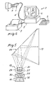
- the intrabuccal detector or sensor of this invention is generally denoted by the numeral 1. It is part of an X-ray apparatus 2 shown in Figure 6 by way of example and comprising, besides the detector 1, a processing unit 3 connected to the detector 1 by means of a cable 4, a keyboard 5 and monitor 6 connected to the processing unit 3, and a printer 7 capable of reproducing the pictures being displayed on the monitor 6.
- FIG. 6 Shown apart in Figure 6 is a tooth 8 flanked on one side by a portion of the detector 1 and on the other side by an X-ray source 9.
- the tooth 8 image is displayed on the monitor 6 which also shows certain processings of that image consisting of magnified details of the tooth 8.
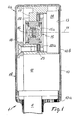
- the intrabuccal detector 1 of this invention has a containment enclosure 10 extending all over its outer surface which has a main dimension crosswise, in the working position, to the direction of propagation of the X-rays, and a small lid 10a at the cable 4.
- the enclosure 10 is light-opaque throughout and preferably opaque to X-radiation as well, with the exception of a pick-up zone 10b parallel to said main dimension of the enclosure 10.
- Two basic zones are distinguishable inside the detector: a first zone 1a extending adjacent a first symmetry axis 11 of the pick-up zone 10b, which is substantially aligned to the X-ray source 9, and a second zone 1b beside the first which contains among others an output signal driver 12.
- This driver 12 is preferably a hybridized driver which processes initially said signals so as to permit, among others, of a remote location of the processing unit 3.
- the first zone 1a is engaged, directly inside the pick-up zone 10b of the enclosure 10, by a planar scintillation screen 13 having the first symmetry axis 11 for its symmetry axis.
- the scintillation screen 13 is, within the enclosure 10, adjacent an opening 14 contiguous to an optical relay or optical system 15 comprising micro-lenses 15a and fitting between the scintillation screen 13 and a CCD sensor 16.
- the scintillation screen 13 is known per se and to a design adapted for converting the X-radiation from the source 9 to light signals having a predetermined wavelength.
- the scintillation screen 13 is envisaged mounted at a location directly adjacent the enclosure 10.
- the enclosure 10 is formed with a sunk area 10b at the screen location.
- the CCD sensor 16 also referred to as charge coupled device or array, is adapted to convert light signals to electric signals, and is preferably selected to have a high resolutive power. It is located away from the scintillation screen 13 and is much smaller in size than the screen.
- the optical relay or optical system 15 is advantageously adapted to concentrate onto the CCD sensor 16 all the light signals output by the scintillation screen 13 and is separated from both the scintillation screen 13 and the sensor 16, but closer to the latter.
- the optical system 15 is facing directly the scintillation screen 13 and has the first symmetry axis 11 for its symmetry axis.
- the optical system 15 fits inside a rigid body 17 opaque to X-radiation, and the CCD sensor 16 lies parallel to the scintillation screen 13, it being engaged with a base 18 which extends into the second zone 1b.
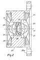
- Figure 2 shows in particular that the optical system 15 is of a symmetrical type with a wide field angle technically recognizable by the term "double-Gauss", and is formed of micro-lenses 15a aligned along the first axis 11 of symmetry.
- the optical system of Figures 1 and 2 is formed of five micro-lenses 15a including: a convex-convex center micro-lens 19, two concave-convex converging meniscus micro-lenses 20 flanking the convex-convex center micro-lens 19 on opposite sides thereof, and two convex-concave diverging meniscus micro-lenses 21 located at the ends of the optical system 17.
- All the micro-lenses 15a are made from known "optical glass” having a high lead content and being therefore opaque to X-ray.
- all the micro-lenses 15a fit in a holder 22, such as an aluminum barrel, which is opaque to X-ray and independent of the scintillation screen 13 and the CCD sensor 16.
- the holder 22 has a flange-like enlargement 22a which engages as by threading with the body 17.
- the threads on the body 17 for threadably receiving the flange 22a is concentrical with she first symmetry axis 11.
- an elastic means 23 e.g. a rubber ring.
- micro-lenses 15a are engaged by means of inside spacers 24 and locking ring nuts 25 at the ends, as shown in Figure 2.
- the locking ring nuts 25 are threaded to the holder 22.
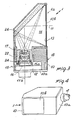
- a reflective element 26 defined by a substantially planar mirror set at an angle of 45° to the scintillation screen 13.
- the body 17 housing the holder 22 which contains the micro-lenses 15a of the optical system 15 and the spacers 24, fits into the second zone 1b, and the optical system 15 has a second symmetry axis 11a parallel to the scintillation screen 13 and above all to said main dimension of the enclosure 10.
- the holder 22 consisting of an aluminum barrel, is engaged as by threading with the body 17 and the threads are concentrical with the second symmetry axis 11a.
- the CCD sensor 16 locates on the opposite side from the reflective element 26 and has the same symmetry axis as the optical system 15. Both the optical system 15 and the CCD sensor 16 contained in the second zone 1b are placed outside the flow cone of X-rays which sweeps the scintillation screen 13. It is envisaged that the overall path of each of the light signals output by the scintillation screen 13 be defined by a first section extending between the scintillation screen 13 and the reflective element 26, and a second reflected section included between the reflective element 26 and the optical system 15.
- said general path extends over a longer distance than the breadth of the enclosure 10 in the direction of the first center symmetry axis 11 orthogonal to the scintillation screen 13.
- the optical system 15, effective to concentrate all the light signals being re-directed by the reflective element 26 onto the CCD sensor 16, is of an asymmetrical type with a small field angle, e.g. of 60°, and the micro-lenses 15a are aligned along the second symmetry axis 11a.
- the small field angle is made possible by the provision of said relatively broad general path of the light signals, as brought about by the reflective element 26.
- the optical system comprises centrally a first converging meniscus concave-convex micro-lens 27 and a first convex-convex micro-lens 28 in mutual contact with their convex sides.
- a plano-concave micro-lens 29 having its planar side facing the concave side of the first concave-convex micro-lens 27, and a second diverging meniscus concave-convex micro-lens 30 with its concave side facing the first convex-convex micro-lens 28.
- a second convex-convex micro-lens 31 mating outwardly with the plano-concave micro-lens 29, and said additional micro-lens consisting of a plano-convex micro-lens 32 having its convex side in contact with the second concave- convex micro-lens 30.
- the detector operates as follows.
- the intrabuccal detector 1 is introduced into the patient's mouth with the sunk area 10b, and hence the scintillation screen 13, facing the part to be radiographed, e.g. a tooth 8 and adjacent gum.
- the X-ray source 9 is positioned perpendicularly to the part to be radiographed and the sunk area 10b outside the mouth, and an emission of X-rays is initiated.
- the radiation will travel through the mouth part to be radiographed generating dark and bright spots making up the X-ray picture, and impinge on the scintillation screen 13 after also going through the sunk area 10b of the enclosure 10.
- the scintillation screen 13 converts the X-radiation to light signals for the CCD sensor 16.
- the light beam is at once strongly concentrated by the micro-lenses 15a of the optical system 15 to produce on the CCD sensor 16 a much smaller picture than that of the scintillation screen 15.
- the light beam will first impinge on the reflective element 26 which divert them over a relatively long distance.
- the optical system 15 requires therefore a relatively small field angle.
- the CCD sensor 15 will then convert the light signals to electric signals, and the latter, following processing in the driver 12, are sent over the cable 4 to the processing unit 3 and thence to the monitor 6 and possibly the printer 7, as shown in Figure 6.
- the invention affords important advantages.
- optical system 15 with micro-lenses 15a allows, within the intrabuccal detector 1, of a strong convergence and concentration of the light beam, which results in a picture of increased brightness and the possibility for attenuating the intensity of the X-radiation.
- the demagnification of the image may be selected as desired within limits, without pre-arranged a priori limitations.
- the whole image is processed by the optical system 15, with no break zones.
- the image sent to the processing unit 3 is particularly sharp and may be liberally processed at high magnifications.
- Another advantage of the inventive detector is that it has minimum bulk dimensions smaller than those of currently known detectors.
- the X-radiation impinging on the detector is either fully converted to light signals or arrested, to prevent it from reaching the CCD sensor or travelling once again through the patient.
- the entire mechanical structure inside the detector is opaque to X-radiation and the micro-lenses 15a are opaque to X-radiation.
- the embodiment of Figures 1 and 2 has to a high degree the quality of being extremely compact and simple, whilst the embodiment of Figures 3 to 5 has the advantage that the distance between the reflective element 26 and the optical system 16 is relatively long and freely increasable during the designing stage, there being no space problems for the intrabuccal detector 1 along its main dimension parallel to the second symmetry axis 11a.
- an optical system with a reduced field angle which enables the brightness of the picture to be uniform throughout without significant variations from the center out.
Landscapes
- Health & Medical Sciences (AREA)
- Life Sciences & Earth Sciences (AREA)
- Medical Informatics (AREA)
- Engineering & Computer Science (AREA)
- Optics & Photonics (AREA)
- Biomedical Technology (AREA)
- Biophysics (AREA)
- High Energy & Nuclear Physics (AREA)
- Oral & Maxillofacial Surgery (AREA)
- Nuclear Medicine, Radiotherapy & Molecular Imaging (AREA)
- Dentistry (AREA)
- Pathology (AREA)
- Radiology & Medical Imaging (AREA)
- Physics & Mathematics (AREA)
- Heart & Thoracic Surgery (AREA)
- Molecular Biology (AREA)
- Surgery (AREA)
- Animal Behavior & Ethology (AREA)
- General Health & Medical Sciences (AREA)
- Public Health (AREA)
- Veterinary Medicine (AREA)
- Measurement Of Radiation (AREA)
- Apparatus For Radiation Diagnosis (AREA)
Applications Claiming Priority (4)
| Application Number | Priority Date | Filing Date | Title |
|---|---|---|---|
| IT8822394A IT1230589B (it) | 1988-10-21 | 1988-10-21 | Captatore intraboccale per apparecchiature radiologiche. |
| IT2239488 | 1988-10-21 | ||
| IT8921245A IT1231159B (it) | 1989-07-20 | 1989-07-20 | Captatore intraboccale perfezionato per apparecchiature radiologiche. |
| IT2124589 | 1989-07-20 |
Publications (1)
| Publication Number | Publication Date |
|---|---|
| EP0364863A1 true EP0364863A1 (de) | 1990-04-25 |
Family
ID=26327844
Family Applications (1)
| Application Number | Title | Priority Date | Filing Date |
|---|---|---|---|
| EP89118800A Ceased EP0364863A1 (de) | 1988-10-21 | 1989-10-10 | In der Mundhöhle angeordneter Sensor für ein Röntgengerät |
Country Status (5)
| Country | Link |
|---|---|
| US (1) | US4987307A (de) |
| EP (1) | EP0364863A1 (de) |
| JP (1) | JPH02164345A (de) |
| AU (1) | AU619602B2 (de) |
| CA (1) | CA2001102A1 (de) |
Cited By (1)
| Publication number | Priority date | Publication date | Assignee | Title |
|---|---|---|---|---|
| FR2701831A1 (fr) * | 1993-02-24 | 1994-09-02 | Angenieux P Ets | Dispositif optique pour la radiographie dentaire. |
Families Citing this family (20)
| Publication number | Priority date | Publication date | Assignee | Title |
|---|---|---|---|---|
| US5138642A (en) * | 1989-03-02 | 1992-08-11 | Innovative Imaging Systems, Inc. | Detector imaging arrangement for an industrial CT device |
| US5150394A (en) | 1989-12-05 | 1992-09-22 | University Of Massachusetts Medical School | Dual-energy system for quantitative radiographic imaging |
| US6031892A (en) * | 1989-12-05 | 2000-02-29 | University Of Massachusetts Medical Center | System for quantitative radiographic imaging |
| US5864146A (en) * | 1996-11-13 | 1999-01-26 | University Of Massachusetts Medical Center | System for quantitative radiographic imaging |
| US5331166A (en) * | 1991-10-25 | 1994-07-19 | Kabushiki Kaisha Morita Seisakusho | Dental X-ray image detecting device with an automatic exposure function |
| US5289520A (en) * | 1991-11-27 | 1994-02-22 | Lorad Corporation | Stereotactic mammography imaging system with prone position examination table and CCD camera |
| US5216250A (en) * | 1991-11-27 | 1993-06-01 | Lorad Corporation | Digital imaging system using CCD array |
| US5434418A (en) * | 1992-10-16 | 1995-07-18 | Schick; David | Intra-oral sensor for computer aided radiography |
| US5723865A (en) * | 1994-11-23 | 1998-03-03 | Thermotrex Corporation | X-ray imaging device |
| DE29506839U1 (de) * | 1995-04-22 | 1995-06-22 | Pfeiffer, Manfred, Dr., London | Intraoral eines Patientenmundes plazierbarer Sensor zur Erstellung von Zahn-/Kieferaufnahmen eines Patienten |
| US5784434A (en) * | 1997-01-16 | 1998-07-21 | Industrial Technology Research Institute | Digital intra-oral imaging system for dental radiography |
| US5912942A (en) | 1997-06-06 | 1999-06-15 | Schick Technologies, Inc. | X-ray detection system using active pixel sensors |
| US6618494B1 (en) | 1998-11-27 | 2003-09-09 | Wuestec Medical, Inc. | Optical distortion correction in digital imaging |
| US6353657B1 (en) | 1998-11-27 | 2002-03-05 | Wuestec Medical, Inc. | Image redirection and optical path folding |
| US6483893B1 (en) | 1998-11-27 | 2002-11-19 | Wuestec Medical, Inc. | Digital high resolution X-ray imaging |
| US6339633B1 (en) | 1998-11-27 | 2002-01-15 | Wuestec Medical, Inc. | Automatic exposure initiation in a digital CCD camera x-ray imager |
| DE10000951A1 (de) * | 2000-01-12 | 2001-05-31 | Siemens Ag | Detektoranordnung für die zerstörungsfreie Werkstoffprüfung |
| DE20017274U1 (de) | 2000-09-18 | 2001-01-04 | roesys GmbH, 32339 Espelkamp | Röntgenvorrichtung |
| US7463716B2 (en) * | 2006-08-04 | 2008-12-09 | X-Scan Imaging Corporation | Linear X-ray detector using rod lens array |
| DE102022115589A1 (de) | 2022-06-22 | 2023-12-28 | Mahdalina Dobrodomova | Röntgenempfangsgerät und bildgebendes Verfahren |
Citations (4)
| Publication number | Priority date | Publication date | Assignee | Title |
|---|---|---|---|---|
| US4298800A (en) * | 1978-02-27 | 1981-11-03 | Computome Corporation | Tomographic apparatus and method for obtaining three-dimensional information by radiation scanning |
| EP0129451A1 (de) * | 1983-06-16 | 1984-12-27 | Francis Mouyen | Gerät zur Aufnahme von Dentalröntgenbildern und insbesondere in der Mundhöhle angeordneter Sensor |
| EP0226661A1 (de) * | 1985-12-24 | 1987-07-01 | Loral Vought Systems Corporation | Verfahren und Mittel zur Durchstrahlungsprüfung |
| EP0268488A2 (de) * | 1986-11-19 | 1988-05-25 | Exxon Research And Engineering Company | Verfahren und Vorrichtung zur Anwendung eines elektrooptischen Detektors in einem mikrotomographischen System |
Family Cites Families (3)
| Publication number | Priority date | Publication date | Assignee | Title |
|---|---|---|---|---|
| US3622785A (en) * | 1970-03-03 | 1971-11-23 | Us Army | Intraoral minimal radiation fluoroscope |
| US4878234A (en) * | 1987-02-16 | 1989-10-31 | Siemens Aktiengesellschaft | Dental x-ray diagnostics installation for producing panorama slice exposures of the jaw of a patient |
| NL8700733A (nl) * | 1987-03-30 | 1988-10-17 | Philips Nv | Dentaal roentgen apparaat. |
-
1989
- 1989-10-10 EP EP89118800A patent/EP0364863A1/de not_active Ceased
- 1989-10-12 AU AU42840/89A patent/AU619602B2/en not_active Ceased
- 1989-10-18 US US07/423,818 patent/US4987307A/en not_active Expired - Fee Related
- 1989-10-20 CA CA002001102A patent/CA2001102A1/en not_active Abandoned
- 1989-10-20 JP JP1271899A patent/JPH02164345A/ja active Pending
Patent Citations (4)
| Publication number | Priority date | Publication date | Assignee | Title |
|---|---|---|---|---|
| US4298800A (en) * | 1978-02-27 | 1981-11-03 | Computome Corporation | Tomographic apparatus and method for obtaining three-dimensional information by radiation scanning |
| EP0129451A1 (de) * | 1983-06-16 | 1984-12-27 | Francis Mouyen | Gerät zur Aufnahme von Dentalröntgenbildern und insbesondere in der Mundhöhle angeordneter Sensor |
| EP0226661A1 (de) * | 1985-12-24 | 1987-07-01 | Loral Vought Systems Corporation | Verfahren und Mittel zur Durchstrahlungsprüfung |
| EP0268488A2 (de) * | 1986-11-19 | 1988-05-25 | Exxon Research And Engineering Company | Verfahren und Vorrichtung zur Anwendung eines elektrooptischen Detektors in einem mikrotomographischen System |
Cited By (1)
| Publication number | Priority date | Publication date | Assignee | Title |
|---|---|---|---|---|
| FR2701831A1 (fr) * | 1993-02-24 | 1994-09-02 | Angenieux P Ets | Dispositif optique pour la radiographie dentaire. |
Also Published As
| Publication number | Publication date |
|---|---|
| JPH02164345A (ja) | 1990-06-25 |
| US4987307A (en) | 1991-01-22 |
| AU4284089A (en) | 1990-04-26 |
| CA2001102A1 (en) | 1990-04-21 |
| AU619602B2 (en) | 1992-01-30 |
Similar Documents
| Publication | Publication Date | Title |
|---|---|---|
| US4987307A (en) | Intrabuccal detector for X-ray Apparatus | |
| EP0217456B1 (de) | Röntgenuntersuchungsgerät mit einem örtlich getrennten Hilfsdetektor | |
| US5138642A (en) | Detector imaging arrangement for an industrial CT device | |
| US4404591A (en) | Slit radiography | |
| DE3467852D1 (en) | Dental radiography imaging device and particularly an intra-buccal sensor | |
| CN110514682B (zh) | 一种x射线小角散射与x射线成像联用的光学系统 | |
| US4829548A (en) | Dental X-ray examination apparatus | |
| CA1228181A (en) | X-ray examination apparatus having a selective filter | |
| JP3454967B2 (ja) | X線診断装置およびx線像検出装置 | |
| US7082187B2 (en) | Radiological image detection system for a scanning X-ray generator | |
| US5739845A (en) | Optical imaging arrangement for use with radiation shielded enclosures | |
| EP0556901B1 (de) | Vorrichtung zur Detektierung von Hochenergiestrahlung | |
| WO1995024720A9 (en) | Optical imaging arrangement for use with radiation shielded enclosures | |
| EP0285214A1 (de) | Dentalröntgengerät | |
| US6587542B1 (en) | Dental panoramic imaging system | |
| JPS5844029A (ja) | 内視鏡 | |
| CA2210853C (en) | Optical arrangement and process for transmitting and converting primary x-ray images | |
| EP0191532A1 (de) | Röntgenstrahlungsuntersuchungs-Vorrichtung | |
| US20240138784A1 (en) | Fluoroscopy barrier | |
| JPH10300858A (ja) | 2次元放射線検出器 | |
| IT1231159B (it) | Captatore intraboccale perfezionato per apparecchiature radiologiche. | |
| IT1230589B (it) | Captatore intraboccale per apparecchiature radiologiche. | |
| JPH0318786A (ja) | 放射線検出装置 | |
| JPH01219831A (ja) | X線撮影用器具及びx線撮影システム | |
| JP2001006586A (ja) | X線イメージ管装置及びこれを用いたx線検査システム |
Legal Events
| Date | Code | Title | Description |
|---|---|---|---|
| PUAI | Public reference made under article 153(3) epc to a published international application that has entered the european phase |
Free format text: ORIGINAL CODE: 0009012 |
|
| AK | Designated contracting states |
Kind code of ref document: A1 Designated state(s): AT BE CH DE ES FR GB GR LI LU NL SE |
|
| 17P | Request for examination filed |
Effective date: 19900511 |
|
| 17Q | First examination report despatched |
Effective date: 19930127 |
|
| STAA | Information on the status of an ep patent application or granted ep patent |
Free format text: STATUS: THE APPLICATION HAS BEEN REFUSED |
|
| 18R | Application refused |
Effective date: 19940207 |