EP0365420B1 - Druckflüssigkeitsmechanismus mit zwei Hubvolumen und seine Anwendung in einem geschlossenen Kreis - Google Patents
Druckflüssigkeitsmechanismus mit zwei Hubvolumen und seine Anwendung in einem geschlossenen Kreis Download PDFInfo
- Publication number
- EP0365420B1 EP0365420B1 EP89402861A EP89402861A EP0365420B1 EP 0365420 B1 EP0365420 B1 EP 0365420B1 EP 89402861 A EP89402861 A EP 89402861A EP 89402861 A EP89402861 A EP 89402861A EP 0365420 B1 EP0365420 B1 EP 0365420B1
- Authority
- EP
- European Patent Office
- Prior art keywords
- conduit
- conduits
- shuttle valve
- fluid
- distribution conduits
- Prior art date
- Legal status (The legal status is an assumption and is not a legal conclusion. Google has not performed a legal analysis and makes no representation as to the accuracy of the status listed.)
- Expired - Lifetime
Links
- 239000012530 fluid Substances 0.000 title claims description 76
- 230000000694 effects Effects 0.000 claims description 8
- 230000003042 antagnostic effect Effects 0.000 claims description 3
- 230000000740 bleeding effect Effects 0.000 claims 3
- 238000006073 displacement reaction Methods 0.000 description 23
- 240000000966 Allium tricoccum Species 0.000 description 5
- 238000005070 sampling Methods 0.000 description 4
- 238000003304 gavage Methods 0.000 description 3
- 241000287107 Passer Species 0.000 description 2
- 238000012550 audit Methods 0.000 description 1
- 230000000295 complement effect Effects 0.000 description 1
- 239000002826 coolant Substances 0.000 description 1
- 238000001816 cooling Methods 0.000 description 1
- 238000010586 diagram Methods 0.000 description 1
- 238000010438 heat treatment Methods 0.000 description 1
- 230000004048 modification Effects 0.000 description 1
- 238000012986 modification Methods 0.000 description 1
- 239000003507 refrigerant Substances 0.000 description 1
- 238000005057 refrigeration Methods 0.000 description 1
Images




Classifications
-
- F—MECHANICAL ENGINEERING; LIGHTING; HEATING; WEAPONS; BLASTING
- F04—POSITIVE - DISPLACEMENT MACHINES FOR LIQUIDS; PUMPS FOR LIQUIDS OR ELASTIC FLUIDS
- F04B—POSITIVE-DISPLACEMENT MACHINES FOR LIQUIDS; PUMPS
- F04B53/00—Component parts, details or accessories not provided for in, or of interest apart from, groups F04B1/00 - F04B23/00 or F04B39/00 - F04B47/00
- F04B53/08—Cooling; Heating; Preventing freezing
-
- F—MECHANICAL ENGINEERING; LIGHTING; HEATING; WEAPONS; BLASTING
- F03—MACHINES OR ENGINES FOR LIQUIDS; WIND, SPRING, OR WEIGHT MOTORS; PRODUCING MECHANICAL POWER OR A REACTIVE PROPULSIVE THRUST, NOT OTHERWISE PROVIDED FOR
- F03C—POSITIVE-DISPLACEMENT ENGINES DRIVEN BY LIQUIDS
- F03C1/00—Reciprocating-piston liquid engines
- F03C1/02—Reciprocating-piston liquid engines with multiple-cylinders, characterised by the number or arrangement of cylinders
- F03C1/04—Reciprocating-piston liquid engines with multiple-cylinders, characterised by the number or arrangement of cylinders with cylinders in star or fan arrangement
- F03C1/0447—Controlling
- F03C1/045—Controlling by using a valve in a system with several pump or motor chambers, wherein the flow path through the chambers can be changed, e.g. series-parallel
-
- F—MECHANICAL ENGINEERING; LIGHTING; HEATING; WEAPONS; BLASTING
- F04—POSITIVE - DISPLACEMENT MACHINES FOR LIQUIDS; PUMPS FOR LIQUIDS OR ELASTIC FLUIDS
- F04B—POSITIVE-DISPLACEMENT MACHINES FOR LIQUIDS; PUMPS
- F04B1/00—Multi-cylinder machines or pumps characterised by number or arrangement of cylinders
- F04B1/04—Multi-cylinder machines or pumps characterised by number or arrangement of cylinders having cylinders in star- or fan-arrangement
- F04B1/06—Control
- F04B1/063—Control by using a valve in a system with several pumping chambers wherein the flow-path through the chambers can be changed, e.g. between series and parallel flow
-
- G—PHYSICS
- G05—CONTROLLING; REGULATING
- G05B—CONTROL OR REGULATING SYSTEMS IN GENERAL; FUNCTIONAL ELEMENTS OF SUCH SYSTEMS; MONITORING OR TESTING ARRANGEMENTS FOR SUCH SYSTEMS OR ELEMENTS
- G05B2219/00—Program-control systems
- G05B2219/20—Pc systems
- G05B2219/25—Pc structure of the system
- G05B2219/25482—Synchronize several sequential processes, adjust
Definitions
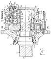
- FR-A-2 481 755 describes a hydraulic motor capable of having two active displacements of different values.
- Such an engine can have many applications and in particular be supplied in a closed circuit.
- Such closed circuits must generally be provided with devices for refrigerating the hydraulic fluid used: the object of the invention is the definition of a simple arrangement making it possible to obtain the cooling of said hydraulic fluid.
- this invention may have other applications and is therefore more generally relating to the complementary device of the known motor.
- This withdrawn fluid can, in the case of a supply in a closed circuit, be refrigerated, then remixed with the rest of the fluid, but can also, in the case of an open circuit, be on the contrary reheated in order to bring more quickly to the good operating temperature the various components of a circuit, including the hydraulic motor itself, or even serve to irrigate elements, momentarily inactive, of hydraulic motors.
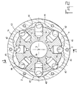
- the invention therefore relates firstly to a pressurized fluid mechanism, motor or pump, comprising two main connections capable of being connected, one to an enclosure containing a high pressure fluid, the other to an enclosure containing a low pressure fluid, and vice versa; a cam with several successive waves, which are distributed in a first and in a second group of distinct waves; a plurality of cylinders, which are arranged in a cylinder block rotatably mounted with respect to said cam; a plurality of pistons, which are slidably mounted in said cylinders, at least one piston per cylinder, and which bear on said cam; an internal fluid distributor comprising as many pairs of first and second distribution conduits as there are waves that the cam comprises, said pairs of distribution conduits being distributed in two distinct groups pairs of a first and a second distribution conduit, each pair corresponding to one of said waves of the cam; a displacement selection member, which is capable of being placed in two distinct positions, a first position, in which the first distribution conduits of the two said groups of distribution conduits are connected to
- a sampling conduit is formed at least partially in said displacement selection member and communicates with said internal conduit of the shuttle valve, which it connects to a fluid discharge via a calibrated restriction .
- the invention also relates to a closed circuit for supplying pressurized fluid to a mechanism with at least two displacements as defined above and which comprises a fluid reservoir, to which the casing of said mechanism is connected by a conduit. evacuation, as well as a booster pump, which comprises a suction duct and a discharge duct and which is connected to said tank by its suction duct, a heat exchanger, the function of which is to refrigerate the fluid sucked by said booster pump, being placed on one of said suction and discharge pipes of the booster pump.
- the main advantage of the mechanism according to the invention lies in its simplicity, the modification made with respect to the previously known mechanism being materially small, although its effectiveness is great.
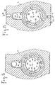
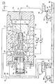
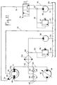
- Figures 7 to 10 show the part of the engine containing the drawer 31 for large-scale displacement selection and the diagram of the supply circuit of this engine with pressurized fluid.
- the displacement selection drawer 31 has two grooves 58 and 59 which, in the first position of this drawer 31 (FIGS. 7 and 8), connect the groove 58, the grooves 26 and 28 of part 1 c of the casing, and, the groove 59, the grooves 27 and 29 of the part 1 c of the casing, while, in the second position of the displacement selection drawer 31 ( Figures 9 and 10), the groove 58 communicates only with the groove 26, and, the groove 59 puts the grooves 28 and 29 into communication, the groove 27 remaining isolated from the grooves 26, 28 and 29.
- This drawer 31 has a central bore 60, which contains a shuttle valve 61 slidably mounted at the interior of this bore and which is closed by a plug 62 screwed into a thread 63.
- a spring 64 is disposed between the cap 36 and the plug 62 and has an effect antagonistic to that of the pressure of the fluid contained in a chamber d end 65 delimited by part 1 c of the casing, one end of the drawer 31 for selecting the displacement and the plug 32.
- the displacement selection drawer 31 is placed in its first position ( Figures 7 and 8); when, on the contrary, the pressure of the fluid contained in the chamber 65 is predominant, the slide 31 of the selection of the displacement is placed in its second position ( Figures 9 and 10).
- the shuttle valve 61 has two separate internal enclosures 66 and 67 and delimits in the bore 60 two end chambers 68 and 69, while the displacement selection drawer 31 has the following conduits: a conduit 70 connecting the groove 58 to the bore 60 by permanently opening into the end chamber 68; a conduit 71 connecting the groove 59 to the bore 60; a conduit 72 connecting the end chamber 69 to the cylindrical face 73 of the drawer 31; a conduit 74 which opens into the bore 60, which it connects, by means of a calibrated restriction 110, to a chamber 77 delimited by the interior of the bore 30, the end of the selection slide 31 of the displacement which is provided with the plug 62 and the cap 36, said chamber 77 communicating with the enclosure 3 of the casing via orifices 78; and a conduit 75, which opens into the cylindrical face 73 and into the bore 60 and is connected to the conduit 74.
- the shuttle valve 61 can occupy a first extreme position (FIGS. 7 and 9 ) in which the volume of the chamber 68 is maximum, and a second extreme position ( Figures 8 and 10) in which it is on the contrary the volume of the chamber 69 which is maximum.
- first extreme position of the shuttle valve 61 FIGGS. 7 and 9
- the conduit 72 and the conduit 71 via a groove 80 of the shuttle valve, communicate with the enclosure 67 and the conduit 74, which conduit 74 also communicates with this groove 80.
- the conduit 72 opens into the groove 27.
- the conduit 70 communicates with a groove 81 of the shuttle valve into which the enclosure 66 opens. It can be observed that, when the drawer 31 for selecting the displacement is placed in its second position, or else (FIG. 9) the fluid contained in the groove 26 and in the chamber 68 a pushed the shuttle valve 61 to the right and therefore has a pressure higher than that of the fluid contained in the chamber 69 and in the groove 27, and the grooves 28 and 29 then contain the fluid at the lowest pressure (grooves 28 and 29 , groove 59, conduit 71, enclosure 67, conduit 72), or else (FIG.
- the fluid contained in the groove 27 and in the chamber 69 has pushed the shuttle valve 61 to the left and therefore has a pressure greater than that of the fluid contained in the chamber 68 and in the groove 26, and the grooves 28 and 29 then contain the fluid at the lowest pressure (grooves 26 and 58, conduit 70, enclosure 66, groove 82 into which the conduit 75 opens, conduit 75). In these two cases, the grooves 28 and 29 contain the fluid at the lowest pressure.
- one of the conduits 74 and 75 communicates with that of the enclosures 66 and 67 containing the fluid at the lowest pressure.
- the shuttle valve 61 is pushed to the right, the chamber 69 containing the fluid at the lowest pressure, the same as that contained in the enclosure 67 and in the grooves 59, 27 and 29: the conduit 74 effectively communicates with the enclosure 67.
- the shuttle valve 61 is pushed to the left, the chamber 68 containing the fluid at the lowest pressure, the same as that contained in the enclosure 66: the conduit 75 communicates with this enclosure 66 .
- the shuttle valve 61 is pushed to the right, the chamber 69 containing the fluid at the lowest pressure, the same as that contained in the enclosure 67: the conduit 74 communicates with the enclosure 67.
- the fluid contained in the conduit 74 pours into the chamber 77, through the calibrated restriction 110, advantageously produced in the form of a removable calibrated nozzle, then pours into the enclosure 3 of the casing via the orifice (s) 78.
- the pistons which are supported on the ramps 42 and 43 move a volume of fluid corresponding to a first cylinder C1, while those which are supported on the ramps 44 and 45 move a volume of fluid corresponding to a cylinder C2.
- These displacements C1, C2 are shown diagrammatically in FIGS. 7 to 9 in the form of two motors M1, M2, respectively.
- the three-position distributor 76 only serves to reverse the direction of supply of the motor, therefore to control the reversal of the direction of rotation of the output shaft 7, or else to keep the engine stopped. It is now assumed that this distributor 76 is placed in its first position ( Figures 7 and 9).
- the drawer 31 isolates each of the grooves 26 and 27, and puts the grooves 28 and 29.
- the motor M1 is supplied by the fluid discharged by the pump 79, the working displacement of the complete motor being equal to C1.
- the motor M2 is supplied by the fluid at the lowest of the pressures (groove 27, conduit 72, enclosure 67, conduit 71, groove 59) and its supply and discharge pressures (grooves 28 and 29) are equal. A certain quantity of the fluid at the lowest of the pressures continues to be withdrawn through the conduit 74 to be treated as described above.
- the inclination of the plate 97 of the pump 96 allows the pressurized fluid to be discharged either to the conduit 103, or to the conduit 104, or even to neither, and to regulate the flow rate of the discharged fluid.
- the two-position distributor 85 allows the cubic capacity (C1 + C2, or only C1) of the motor to be selected and the fluid withdrawn returns to the reservoir 84 via the conduit 55.
- the pump 96 and the motor (M1 + M2) are connected in a closed circuit (conduits 103 and 104). If, in such a circuit, in addition to the usual leaks, part of the fluid is withdrawn, it is necessary to replace the withdrawn fluid.
- the booster pump 98 precisely has the function of reintroducing, into that of the conduits 103 and 104 which contains the low pressure fluid, an amount of fluid equal to that which has been withdrawn.
Landscapes
- Engineering & Computer Science (AREA)
- Mechanical Engineering (AREA)
- General Engineering & Computer Science (AREA)
- Chemical & Material Sciences (AREA)
- Combustion & Propulsion (AREA)
- Fluid-Pressure Circuits (AREA)
- Hydraulic Motors (AREA)
- Multiple-Way Valves (AREA)
Claims (4)
daß die Abgriffleitung zwei Zweige (74, 75) umfaßt, von denen einer (74) in der ersten Position des Pendelventils mit einer (67) der zwei erwähnten internen Leitungen des Pendelventils und der andere (75) in der zweiten Position des Pendelventils mit der anderen (66) der zwei erwähnten Leitungen des Pendelventils verbunden ist.
Applications Claiming Priority (2)
| Application Number | Priority Date | Filing Date | Title |
|---|---|---|---|
| FR8813762 | 1988-10-19 | ||
| FR8813762A FR2637944B1 (fr) | 1988-10-19 | 1988-10-19 | Mecanisme a fluide sous pression a deux cylindrees et circuit ferme en faisant application |
Publications (2)
| Publication Number | Publication Date |
|---|---|
| EP0365420A1 EP0365420A1 (de) | 1990-04-25 |
| EP0365420B1 true EP0365420B1 (de) | 1992-04-15 |
Family
ID=9371167
Family Applications (1)
| Application Number | Title | Priority Date | Filing Date |
|---|---|---|---|
| EP89402861A Expired - Lifetime EP0365420B1 (de) | 1988-10-19 | 1989-10-17 | Druckflüssigkeitsmechanismus mit zwei Hubvolumen und seine Anwendung in einem geschlossenen Kreis |
Country Status (5)
| Country | Link |
|---|---|
| US (1) | US5001964A (de) |
| EP (1) | EP0365420B1 (de) |
| JP (1) | JPH02225858A (de) |
| DE (1) | DE68901245D1 (de) |
| FR (1) | FR2637944B1 (de) |
Families Citing this family (9)
| Publication number | Priority date | Publication date | Assignee | Title |
|---|---|---|---|---|
| FR2694342B1 (fr) * | 1992-07-28 | 1994-10-21 | Poclain Hydraulics Sa | Moteur à fluide sous pression comportant un ralentisseur interne et groupe d'entraînement en faisant application et comportant un organe d'immobilisation. |
| FR2710111B1 (fr) * | 1993-09-15 | 1995-12-01 | Poclain Hydraulics Sa | Moteur hydraulique muni d'un dispositif de sélection de sa cylindrée active. |
| AU5964499A (en) * | 1998-10-07 | 2000-04-26 | Ker-Train Holdings Ltd. | Rotary pump |
| EP1255930B1 (de) * | 2000-02-17 | 2005-06-01 | Bosch Rexroth AG | Hydraulische steuerschaltung für einen hydromotor mit mindestens zwei geschwindigkeiten |
| FR3002985B1 (fr) * | 2013-03-05 | 2015-04-03 | Poclain Hydraulics Ind | Ensemble hydraulique comprenant un circuit de gavage ameliore |
| FR3043433B1 (fr) * | 2015-11-10 | 2017-12-08 | Poclain Hydraulics Ind | Dispositif de distribution pour une machine hydraulique et machine hydraulique equipee d'un tel dispositif |
| DE102017205846A1 (de) * | 2017-04-06 | 2018-10-11 | Robert Bosch Gmbh | Hydraulischer Antrieb für die Vorschubwalzen eines Kopfes eines Holzvollernters |
| EP4102051A1 (de) * | 2021-06-07 | 2022-12-14 | Robert Bosch GmbH | Mehrkolbenmaschine mit mindestens drei schaltbaren verdrängungsvolumen |
| FR3135305A1 (fr) * | 2022-05-06 | 2023-11-10 | Poclain Hydraulics Industrie | Machine hydraulique munie d’un tiroir de changement de sens |
Family Cites Families (7)
| Publication number | Priority date | Publication date | Assignee | Title |
|---|---|---|---|---|
| US3266436A (en) * | 1964-09-01 | 1966-08-16 | Donald L Yarger | Multiple piston type pump or motor |
| FR2292877A1 (fr) * | 1975-07-16 | 1976-06-25 | Poclain Sa | Moteur hydraulique a plusieurs cylindrees |
| US4121501A (en) * | 1977-07-11 | 1978-10-24 | Caterpillar Tractor Co. | Flow combining system for dual pumps |
| US4293000A (en) * | 1978-10-06 | 1981-10-06 | Tadeusz Budzich | Load responsive fluid control valve |
| FR2481755A1 (fr) * | 1980-04-30 | 1981-11-06 | Poclain Hydraulics Sa | Moteur a fluide sous pression muni d'un dispositif de selection de sa vitesse de rotation |
| DE3446134A1 (de) * | 1984-12-18 | 1986-06-26 | G. Düsterloh GmbH, 4322 Sprockhövel | Reversierbare hydraulische maschine |
| DE3706460A1 (de) * | 1986-10-31 | 1988-09-08 | Rexroth Mannesmann Gmbh | Kolbenmaschine mit umschaltbarem hubraum |
-
1988
- 1988-10-19 FR FR8813762A patent/FR2637944B1/fr not_active Expired - Lifetime
-
1989
- 1989-10-16 US US07/422,110 patent/US5001964A/en not_active Expired - Lifetime
- 1989-10-17 DE DE8989402861T patent/DE68901245D1/de not_active Expired - Lifetime
- 1989-10-17 EP EP89402861A patent/EP0365420B1/de not_active Expired - Lifetime
- 1989-10-18 JP JP89271437A patent/JPH02225858A/ja active Pending
Also Published As
| Publication number | Publication date |
|---|---|
| JPH02225858A (ja) | 1990-09-07 |
| EP0365420A1 (de) | 1990-04-25 |
| US5001964A (en) | 1991-03-26 |
| FR2637944A1 (fr) | 1990-04-20 |
| FR2637944B1 (fr) | 1991-01-25 |
| DE68901245D1 (de) | 1992-05-21 |
Similar Documents
| Publication | Publication Date | Title |
|---|---|---|
| EP0223656B1 (de) | Mechanismus, Motor oder Pumpe mit mindestens zwei verschiedenen aktiven Hubvolumen | |
| EP0284460B1 (de) | Druckflüssigkeitsmechanismus, Pumpe oder Motor mit mehreren Verdrängungsvolumen | |
| EP0365420B1 (de) | Druckflüssigkeitsmechanismus mit zwei Hubvolumen und seine Anwendung in einem geschlossenen Kreis | |
| EP2617985B1 (de) | Hydraulische Getriebevorrichtung mit mehreren Zylindern | |
| EP0006045A1 (de) | Steuervorrichtung für einen hydraulischen Kreislauf und autonomer Stellmotor, in dem dieser Kreislauf integriert ist | |
| FR2677409A1 (fr) | Circuit hydraulique d'alimentation d'au moins un moteur hydraulique a pistons "debrayables". | |
| FR2706538A1 (fr) | Mécanisme à fluide sous pression tel qu'un moteur ou une pompe, réversible, à au moins deux cylindrées de fonctionnement. | |
| FR2481755A1 (fr) | Moteur a fluide sous pression muni d'un dispositif de selection de sa vitesse de rotation | |
| EP0601916A1 (de) | Hydraulikmotoraggegrat zum Antrieb eines Bohrwerkzeuges | |
| FR2780450A1 (fr) | Moteur hydraulique compact | |
| EP0921309B1 (de) | Hydraulikmotor mit Schaltventil | |
| EP2376769B1 (de) | Hydraulikgetriebekreis | |
| FR2678322A1 (fr) | Mecanisme a fluide sous pression comportant au moins deux cylindrees distinctes de fonctionnement. | |
| FR2846381A1 (fr) | Mecanisme hydraulique ayant des cylindres a communications multiples | |
| EP1072791B1 (de) | Radialkolbenmotor mit einer einzigen Koppelauswahlvorrichtung | |
| FR2655091A1 (fr) | Ensemble d'un mecanisme a fluide sous pression et d'un frein a disques qui y est attele. | |
| FR2641335A1 (fr) | Pompe d'injection de carburant a commande electrique, a plusieurs pistons ou le piston rotatif est lui-meme utilise comme vanne de commande d'alimentation de carburant | |
| EP0582498B1 (de) | Steuervorrichtung für mehrere hydraulische Verbraucher | |
| FR2661456A1 (fr) | Mecanisme a fluide sous pression, tel qu'un moteur ou une pompe hydraulique, a plusieurs cylindrees de fonctionnement. | |
| EP0526333A1 (de) | Druckflüssigkeitsvorrichtung mit Ausgleichsräumen | |
| EP0607069B1 (de) | Flüssigkeitsmotorkolben | |
| EP0582497B1 (de) | Steuervorrichtung für mehrere hydraulische Verbraucher | |
| FR2736124A1 (fr) | Ensemble hydrostatique a patinage controle | |
| EP1355068A1 (de) | Vorrichtung zur Teilung oder zum Zusammenfügen einer Strömung | |
| FR2467284A1 (fr) | Dispositif de commande d'un moteur a fluide, notamment hydraulique, et installation equipee d'un tel dispositif |
Legal Events
| Date | Code | Title | Description |
|---|---|---|---|
| PUAI | Public reference made under article 153(3) epc to a published international application that has entered the european phase |
Free format text: ORIGINAL CODE: 0009012 |
|
| AK | Designated contracting states |
Kind code of ref document: A1 Designated state(s): DE GB |
|
| 17P | Request for examination filed |
Effective date: 19900619 |
|
| 17Q | First examination report despatched |
Effective date: 19910723 |
|
| GRAA | (expected) grant |
Free format text: ORIGINAL CODE: 0009210 |
|
| AK | Designated contracting states |
Kind code of ref document: B1 Designated state(s): DE GB |
|
| REF | Corresponds to: |
Ref document number: 68901245 Country of ref document: DE Date of ref document: 19920521 |
|
| GBT | Gb: translation of ep patent filed (gb section 77(6)(a)/1977) | ||
| PLBE | No opposition filed within time limit |
Free format text: ORIGINAL CODE: 0009261 |
|
| STAA | Information on the status of an ep patent application or granted ep patent |
Free format text: STATUS: NO OPPOSITION FILED WITHIN TIME LIMIT |
|
| 26N | No opposition filed | ||
| REG | Reference to a national code |
Ref country code: GB Ref legal event code: 732E |
|
| REG | Reference to a national code |
Ref country code: GB Ref legal event code: IF02 |
|
| PGFP | Annual fee paid to national office [announced via postgrant information from national office to epo] |
Ref country code: DE Payment date: 20031008 Year of fee payment: 15 |
|
| PGFP | Annual fee paid to national office [announced via postgrant information from national office to epo] |
Ref country code: GB Payment date: 20031010 Year of fee payment: 15 |
|
| PG25 | Lapsed in a contracting state [announced via postgrant information from national office to epo] |
Ref country code: GB Free format text: LAPSE BECAUSE OF NON-PAYMENT OF DUE FEES Effective date: 20041017 |
|
| PG25 | Lapsed in a contracting state [announced via postgrant information from national office to epo] |
Ref country code: DE Free format text: LAPSE BECAUSE OF NON-PAYMENT OF DUE FEES Effective date: 20050503 |
|
| GBPC | Gb: european patent ceased through non-payment of renewal fee |
Effective date: 20041017 |