EP0365715B1 - Dispositif de changement de vitesse pour une boîte automatique de véhicule automobile - Google Patents
Dispositif de changement de vitesse pour une boîte automatique de véhicule automobile Download PDFInfo
- Publication number
- EP0365715B1 EP0365715B1 EP88118933A EP88118933A EP0365715B1 EP 0365715 B1 EP0365715 B1 EP 0365715B1 EP 88118933 A EP88118933 A EP 88118933A EP 88118933 A EP88118933 A EP 88118933A EP 0365715 B1 EP0365715 B1 EP 0365715B1
- Authority
- EP
- European Patent Office
- Prior art keywords
- selector lever
- gearshift
- path
- gear
- shifting
- Prior art date
- Legal status (The legal status is an assumption and is not a legal conclusion. Google has not performed a legal analysis and makes no representation as to the accuracy of the status listed.)
- Expired - Lifetime
Links
Images

Classifications
-
- F—MECHANICAL ENGINEERING; LIGHTING; HEATING; WEAPONS; BLASTING
- F16—ENGINEERING ELEMENTS AND UNITS; GENERAL MEASURES FOR PRODUCING AND MAINTAINING EFFECTIVE FUNCTIONING OF MACHINES OR INSTALLATIONS; THERMAL INSULATION IN GENERAL
- F16H—GEARING
- F16H59/00—Control inputs to control units of change-speed- or reversing-gearings for conveying rotary motion
- F16H59/02—Selector apparatus
- F16H59/08—Range selector apparatus
- F16H59/10—Range selector apparatus comprising levers
- F16H59/105—Range selector apparatus comprising levers consisting of electrical switches or sensors
-
- F—MECHANICAL ENGINEERING; LIGHTING; HEATING; WEAPONS; BLASTING
- F16—ENGINEERING ELEMENTS AND UNITS; GENERAL MEASURES FOR PRODUCING AND MAINTAINING EFFECTIVE FUNCTIONING OF MACHINES OR INSTALLATIONS; THERMAL INSULATION IN GENERAL
- F16H—GEARING
- F16H59/00—Control inputs to control units of change-speed- or reversing-gearings for conveying rotary motion
- F16H59/02—Selector apparatus
- F16H59/0204—Selector apparatus for automatic transmissions with means for range selection and manual shifting, e.g. range selector with tiptronic
-
- F—MECHANICAL ENGINEERING; LIGHTING; HEATING; WEAPONS; BLASTING
- F16—ENGINEERING ELEMENTS AND UNITS; GENERAL MEASURES FOR PRODUCING AND MAINTAINING EFFECTIVE FUNCTIONING OF MACHINES OR INSTALLATIONS; THERMAL INSULATION IN GENERAL
- F16H—GEARING
- F16H59/00—Control inputs to control units of change-speed- or reversing-gearings for conveying rotary motion
- F16H2059/006—Overriding automatic control
-
- F—MECHANICAL ENGINEERING; LIGHTING; HEATING; WEAPONS; BLASTING
- F16—ENGINEERING ELEMENTS AND UNITS; GENERAL MEASURES FOR PRODUCING AND MAINTAINING EFFECTIVE FUNCTIONING OF MACHINES OR INSTALLATIONS; THERMAL INSULATION IN GENERAL
- F16H—GEARING
- F16H59/00—Control inputs to control units of change-speed- or reversing-gearings for conveying rotary motion
- F16H59/02—Selector apparatus
- F16H2059/0239—Up- and down-shift or range or mode selection by repeated movement
-
- F—MECHANICAL ENGINEERING; LIGHTING; HEATING; WEAPONS; BLASTING
- F16—ENGINEERING ELEMENTS AND UNITS; GENERAL MEASURES FOR PRODUCING AND MAINTAINING EFFECTIVE FUNCTIONING OF MACHINES OR INSTALLATIONS; THERMAL INSULATION IN GENERAL
- F16H—GEARING
- F16H61/00—Control functions within control units of change-speed- or reversing-gearings for conveying rotary motion ; Control of exclusively fluid gearing, friction gearing, gearings with endless flexible members or other particular types of gearing
- F16H61/16—Inhibiting or initiating shift during unfavourable conditions , e.g. preventing forward-reverse shift at high vehicle speed, preventing engine overspeed
- F16H2061/161—Inhibiting or initiating shift during unfavourable conditions , e.g. preventing forward-reverse shift at high vehicle speed, preventing engine overspeed by checking feasibility of shifts, i.e. determine if requested shift can be successfully completed and post shift values are in an acceptable range
-
- F—MECHANICAL ENGINEERING; LIGHTING; HEATING; WEAPONS; BLASTING
- F16—ENGINEERING ELEMENTS AND UNITS; GENERAL MEASURES FOR PRODUCING AND MAINTAINING EFFECTIVE FUNCTIONING OF MACHINES OR INSTALLATIONS; THERMAL INSULATION IN GENERAL
- F16H—GEARING
- F16H59/00—Control inputs to control units of change-speed- or reversing-gearings for conveying rotary motion
- F16H59/02—Selector apparatus
- F16H59/08—Range selector apparatus
- F16H59/10—Range selector apparatus comprising levers
-
- F—MECHANICAL ENGINEERING; LIGHTING; HEATING; WEAPONS; BLASTING
- F16—ENGINEERING ELEMENTS AND UNITS; GENERAL MEASURES FOR PRODUCING AND MAINTAINING EFFECTIVE FUNCTIONING OF MACHINES OR INSTALLATIONS; THERMAL INSULATION IN GENERAL
- F16H—GEARING
- F16H61/00—Control functions within control units of change-speed- or reversing-gearings for conveying rotary motion ; Control of exclusively fluid gearing, friction gearing, gearings with endless flexible members or other particular types of gearing
- F16H61/16—Inhibiting or initiating shift during unfavourable conditions , e.g. preventing forward-reverse shift at high vehicle speed, preventing engine overspeed
-
- Y—GENERAL TAGGING OF NEW TECHNOLOGICAL DEVELOPMENTS; GENERAL TAGGING OF CROSS-SECTIONAL TECHNOLOGIES SPANNING OVER SEVERAL SECTIONS OF THE IPC; TECHNICAL SUBJECTS COVERED BY FORMER USPC CROSS-REFERENCE ART COLLECTIONS [XRACs] AND DIGESTS
- Y10—TECHNICAL SUBJECTS COVERED BY FORMER USPC
- Y10T—TECHNICAL SUBJECTS COVERED BY FORMER US CLASSIFICATION
- Y10T74/00—Machine element or mechanism
- Y10T74/19—Gearing
- Y10T74/19219—Interchangeably locked
- Y10T74/19251—Control mechanism
Definitions
- the invention relates to a switching device for an automatic transmission of a motor vehicle according to the preamble of claim 1.
- a switching device for an automatic transmission of a motor vehicle which a program "Manual gear selection" of an automatic transmission controlled by an electronic control unit according to Bosch, Technical Reports 7 (1983) 4, pages 160-166, with the Makes selector lever feasible.
- a program switch which enables a driver to choose between an economy program, a performance program and a program for manual selection of the transmission gears via the selector lever can be omitted.
- the gearbox can be designed to be more user-friendly and can be manufactured more cost-effectively.
- the selector lever can be switched via a cross gate into a second shift gate parallel to the first shift gate and that the forward gears (1, 2, 3, 4) of the transmission can be shifted manually when the selector lever is pivoted in the second shift gate are.
- the selector lever in the second shift gate is designed as a rocker arm, which triggers a downshift in one direction and an upshift of the automatic transmission in the other direction when pivoting from a stable central position (rest position).
- a control unit for controlling the transmission comprising a switchover unit which, when the selector lever is inserted from the first shift gate into the second shift gate, maintains the current gear speed at least as long as a rotational speed of a drive internal combustion engine has not yet exceeded an upper speed limit or has not yet fallen below a lower speed limit, or the selector lever in the second shift gate has not yet been pivoted to trigger an upshift / downshift.
- the currently engaged transmission gear is maintained at least until the control unit has made an automatic transmission gear adjustment or until the internal combustion engine has reached its speed limits.
- the selector positions are detected by sensors 4 to 10, which send electrical signals sp, sr, sn, sd, s3, s2 and s1 to a control unit 11 of the transmission 3. From the selector position D, the selector lever 1 can be switched via a transverse lane 12 into a switching lane 13 parallel to the first switching lane 2. The switching process is detected by a sensor 14, which delivers a signal sm to the control unit 11.
- a minus sensor 15 responds, the signal kvr of which causes the control unit 11 to shift down one gear via transmission control signals gs on the transmission 3. Then the selector lever 1 is pressed back by a spring 16 into the neutral central position of the shift gate 13. When tapping again on sensor 15, there is a further downshift by one gear, if the highest gear is not already engaged.
- a plus sensor 17 emits a signal kvh to the control unit 11 and triggers an upshift by one gear on the transmission 3.
- a manually requested upshift is only carried out if an engine speed nmot of an internal combustion engine 18 driving the transmission 3 in the next higher gear does not fall below a minimum speed nmin; Accordingly, a downshift designed on selector lever 1 is suppressed if the engine speed nmot in the next lower gear would exceed the maximum engine speed nmax.
- the engine speed nmot is determined via an engine speed sensor 19 and, like a transmission output speed ne (vehicle speed sensor 20), an engine load signal ml (air volume, air mass or throttle valve position sensor 21) and an accelerator pedal position signal fs of an accelerator pedal position sensor 22, are made available to the control unit 11, which is made up of the given input signal combination and the currently selected transmission gear stage k, the transmission control signals gs are determined in accordance with the manual gear preselection or a conventional automatic program.
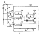
- the control unit 11 which can be implemented, for example, in accordance with Bosch Technical Reports 7 (1983) 4, pages 160 to 166, is now expanded as follows: a switchover unit 23 is integrated into it, the subunit 24 of which, in particular based on the signal sm from the sensor 14, the control unit 11 Influenced by the fact that when the selector lever 1 is inserted out of the first shift gate 2 into the second shift gate 13, the currently engaged transmission gear k is maintained at least as long as a rotational speed nmot of a drive internal combustion engine 18 has not yet exceeded the upper rotational speed limit nmax or the lower one Has not yet fallen below the speed limit nmin or the selector lever 1 in the second shift gate 13 has not yet been pivoted to trigger an upshift or downshift.
- the sub-unit 24 of the switchover unit 23 influences the control unit 11 such that when the selector lever 1 is inserted from the second shift gate 13 into the first shift gate 2, the currently engaged transmission gear k is maintained at least until the control unit 11 adjusts the transmission gear automatically or how a speed nmot of a drive internal combustion engine 18 has not yet exceeded the first upper speed limit or has not yet fallen below the second lower speed limit.
- the switching unit 23 further comprises a second sub-unit 25, which prevents the internal combustion engine from starting when a selector lever is located in the second shift gate 13; in particular, starting the internal combustion engine is only permitted in a parking position P and a neutral position N of the selector lever in the first shift gate: for this purpose, the second subunit 25 of the switching unit 23 detects the signals sp and sn of the selector lever positions P and N of the selector lever 1 in the first shift gate 2 comprehensive sensors 4 and 6.
- the signals sp and sn are linked to one another via an OR gate 26; the OR gate 26 controls a relay 27 via a starter enable signal as.
- the relay 27 interrupts a control circuit 28 of a start relay 30 which triggers the starting of the internal combustion engine 18 by means of the starter 29.
- the control circuit 28 is formed here by a series connection of an ignition switch 32, a start switch 33, the make contact 34, which is connected to a battery 31 of relay 27 and a coil 35 of start relay 30.
- the sensors 14 and 15 and 17 are designed as limit switches limit switches, which are in the unactuated state on earth (negative pole of the battery 31) and in the actuated state (selector lever in the second switching gate 13 or in one of the two end positions) via a series resistor Rv and the ignition switch 32 on the positive pole of the battery 31.
- the signal sm generated in this way is connected to a first static, retriggerable monoflop 36 (monostable multivibrator) for debouncing the contact, via the output of which a second, pulse-edge-controlled, non-retriggerable monoflop 37 is controlled; this generates a first interrupt signal INT1 on a positive pulse edge.
- the output of the first monoflop 36 drives a third pulse-edge-controlled, non-retriggerable monoflop 38, which generates a second interrupt signal INT2 at the output Q of the first monoflop 36 on a negative pulse edge.
- the signals kvr and kvh are generated by means of a fourth and fifth, a third and a fourth interrupt signal INT3, INT4. retriggerable, statically controlled monoflops 39 and 40 debounced, which can be integrated in the switching unit 23 (but need not).
- the first interrupt signal INT1 is used in control unit 11 to switch from automatic gear selection to manual gear selection, for example by setting a flag; the switchover in the opposite direction is effected by the second interrupt signal INT2, which resets the flag.
- the program running in the control unit 11 for generating the transmission control signals gs generally provides for a continuously running program loop, in which all input signals of the control unit 11 are determined.
- the limit speeds of the internal combustion engine 18 nmax, nmin
- the flag is queried and, depending on the state of the flag, a manual or automatic gear adjustment is carried out and, if appropriate, is shifted up or down.
- the interruption signal INT1 can leave the automatic gear adjustment at any time and the program run can be restarted; In this way, a currently engaged gear is maintained. Likewise, the interruption signal INT2 exits the manual gear adjustment and the program run is started again.
- the interrupt signals INT3 and INT4 each decrease or increase a gear stage preselection counter; in the manual gear adjustment, the gear step is then adapted to the level of the gear step preselection counter.
Landscapes
- Engineering & Computer Science (AREA)
- General Engineering & Computer Science (AREA)
- Mechanical Engineering (AREA)
- Control Of Transmission Device (AREA)
- Arrangement Or Mounting Of Control Devices For Change-Speed Gearing (AREA)
Claims (5)
- Dispositif de changement de vitesse pour une boîte automatique à commande électronique d'un véhicule automobile, comportant un levier de sélection dont le pivotement dans une première voie de commutation permet de présélectionner les différents rapports à commuter automatiquement, le levier de sélection (1) pouvant commuter, par une voie transversale, dans une seconde voie de commutation (12), parallèle à la première voie de commutation (2), et dans lequel le pivotement du levier de sélection (1) dans la seconde voie de commutation (13) permet de commander manuellement les marches avant (1, 2, 3, 4) de la boîte de vitesses, caractérisé en ce que l'appareil de commande (11) comporte une unité de commutation (23, 24), influencée par un capteur (14), détectant le passage de la première voie (2) à la seconde voie (13), laquelle unité de commutation, lorsque le levier de sélection (1), quittant la première voie de commutation (2) est introduit dans la seconde voie de commutation (13), provoque un maintien du rapport (k) actuellement engagé, au moins jusqu'à ce que la vitesse de rotation (nmot) du moteur à combustion interne (18), entraînant la boîte de vitesses, dépasse une vitesse limite supérieure (nmax) ou devienne inférieure à une vitesse limite inférieure (nmin), ou jusqu'à ce que le levier de sélection (1) soit pivoté dans la séconde voie de commutation (13).
- Dispositif de changement de vitesse selon la revendication 1, caractérisé en ce que dans la seconde voie de commutation, par pivotement unique du levier de sélection (1) dans un sens, à partir de la position centrale de point mort et par contact avec un capteur plus (17), il est possible de commander manuellement un passage à la vitesse supérieure, et par pivotement unique du levier de sélection (1) dans le sens opposé et contact sur un capteur moins (15), un passage à une vitesse inférieure et en ce que le levier de sélection (1) est ensuite automatiquement replacé dans la position centrale de point mort.
- Dispositif de changement de vitesse selon les revendications 1 ou 2, caractérisé en ce que l'unité de commutation (23, 24), lorsque le levier de sélection (1) est introduit, à partir de la seconde voie de commutation (13) dans la première voie de commutation (2), provoque un maintien du rapport (k) actuellement engagé, au moins jusqu'à ce que l'appareil de commande (11) procède à une nouvelle adaptation automatique du rapport ou jusqu'à ce que la vitesse de rotation (nmot) du moteur à combustion interne (18) d'entraînement dépasse la vitesse limite supérieure (nmax) ou devienne inférieure à la seconde vitesse limite (nmin).
- Dispositif de changement de vitesse selon la revendication 3, caractérisé en ce que l'unité de commutation (23, 25) empêche un démarrage du moteur à combustion interne (18), lorsque le levier de sélection (1) se trouve dans la seconde voie de commutation (13).
- Dispositif de changement de vitesse selon l'une au moins des revendications précédentes, caractérisé en ce que l'unité de commutation (23, 25) autorise un démarrage du moteur à combustion interne (8) uniquement en position de garage (P) et dans une position de point mort (N) du levier de sélection (1) dans la première voie de conmutation (2).
Applications Claiming Priority (2)
| Application Number | Priority Date | Filing Date | Title |
|---|---|---|---|
| DE3832969 | 1988-09-29 | ||
| DE3832969A DE3832969A1 (de) | 1988-03-10 | 1988-09-29 | Schaltvorrichtung fuer ein automatikgetriebe eines kraftfahrzeugs |
Publications (2)
| Publication Number | Publication Date |
|---|---|
| EP0365715A1 EP0365715A1 (fr) | 1990-05-02 |
| EP0365715B1 true EP0365715B1 (fr) | 1993-06-02 |
Family
ID=6363910
Family Applications (1)
| Application Number | Title | Priority Date | Filing Date |
|---|---|---|---|
| EP88118933A Expired - Lifetime EP0365715B1 (fr) | 1988-09-29 | 1988-11-14 | Dispositif de changement de vitesse pour une boîte automatique de véhicule automobile |
Country Status (5)
| Country | Link |
|---|---|
| US (1) | US4905530A (fr) |
| EP (1) | EP0365715B1 (fr) |
| JP (1) | JP3152913B2 (fr) |
| DE (1) | DE3881524D1 (fr) |
| HK (1) | HK68297A (fr) |
Cited By (1)
| Publication number | Priority date | Publication date | Assignee | Title |
|---|---|---|---|---|
| US6872269B2 (en) | 2003-03-22 | 2005-03-29 | Henkel Kommanditgesellschaft Auf Aktien | Process for bonding contaminated substrates |
Families Citing this family (45)
| Publication number | Priority date | Publication date | Assignee | Title |
|---|---|---|---|---|
| ES2007211A6 (es) * | 1987-05-27 | 1989-06-01 | Zahnradfabrik Friedrichshafen | Dispositivo de mando. |
| US4991454A (en) * | 1989-12-01 | 1991-02-12 | Ford New Holland, Inc. | Power shift transmission shift pattern |
| JP2748642B2 (ja) * | 1990-03-12 | 1998-05-13 | トヨタ自動車株式会社 | 自動変速機の制御装置 |
| FR2664959B1 (fr) * | 1990-07-17 | 1995-06-16 | Renault | Dispositif de commande manuelle de boite de vitesses automatique. |
| GB2256683B (en) * | 1991-06-15 | 1994-05-25 | Gen Motors France | Transmission control module |
| EP0567157B1 (fr) * | 1992-04-24 | 1996-07-03 | Toyota Jidosha Kabushiki Kaisha | Système de commande de changement de vitesses pour transmission automatique où les vitesses peuvent être changées manuellement |
| US5415056A (en) * | 1992-09-21 | 1995-05-16 | Toyota Jidosha Kabushiki Kaisha | Shift control system for manually shiftable automatic transmission |
| FR2703958B1 (fr) * | 1993-04-13 | 1995-07-13 | Jaeger | Ensemble de commande pour boite de vitesses mecanique et systeme de commande incorporant celui-ci. |
| FR2705129B1 (fr) * | 1993-05-11 | 1995-08-11 | Peugeot | Dispositif formant commande de vitesses pour boîte de vitesses automatique de véhicule. |
| US5388476A (en) * | 1993-06-15 | 1995-02-14 | Agco Corporation | Gearshift mechanism |
| US5509322A (en) * | 1994-06-02 | 1996-04-23 | Chrysler Corporation | Shift control mechanism to manually shift an automatic transmission |
| US5722292A (en) * | 1994-06-02 | 1998-03-03 | Chrysler Corporation | Shift control mechanism to manually shift an automatic transmission |
| US5492509A (en) * | 1994-06-06 | 1996-02-20 | Ford Motor Company | Operating range selection of an automatic transmission |
| US5762580A (en) * | 1994-06-06 | 1998-06-09 | Ford Global Technologies, Inc. | Operating range selection of an automatic transmission |
| US5492523A (en) * | 1994-06-06 | 1996-02-20 | Ford Motor Company | Operating range selection of an automatic transmission |
| JP3104160B2 (ja) * | 1995-02-01 | 2000-10-30 | 本田技研工業株式会社 | 車両用自動変速機の制御装置 |
| JP3231205B2 (ja) * | 1995-02-01 | 2001-11-19 | 本田技研工業株式会社 | 車両用自動変速機の制御装置 |
| JP3176522B2 (ja) * | 1995-02-06 | 2001-06-18 | 本田技研工業株式会社 | 車両用自動変速機の制御装置 |
| US5767769A (en) * | 1995-07-28 | 1998-06-16 | Chrysler Corporation | Method of displaying a shift lever position for an electronically-controlled automatic transmission |
| US5680307A (en) * | 1995-06-28 | 1997-10-21 | Chrysler Corporation | Method of shifting in a manual mode of an electronically-controlled automatic transmission system |
| KR970006831A (ko) * | 1995-07-28 | 1997-02-21 | 배순훈 | 자동차의 급가속제어장치 |
| DE19706625B4 (de) * | 1996-03-01 | 2006-05-04 | Volkswagen Ag | Fahrstufenschaltvorrichtung für ein Automatikgetriebe |
| JP3911749B2 (ja) * | 1996-03-29 | 2007-05-09 | マツダ株式会社 | 自動変速機の制御装置 |
| DE19612856A1 (de) * | 1996-03-30 | 1997-10-02 | Bayerische Motoren Werke Ag | Schalteinrichtung |
| US5791197A (en) * | 1996-07-24 | 1998-08-11 | Grand Haven Stamped Products | Automatic transmission shifter with manual shift mode |
| JP3216542B2 (ja) * | 1996-09-02 | 2001-10-09 | トヨタ自動車株式会社 | 自動変速機の変速レンジ制御装置 |
| JP3339367B2 (ja) | 1997-07-11 | 2002-10-28 | 日産自動車株式会社 | 無段変速機の制御装置 |
| JP3339370B2 (ja) | 1997-07-25 | 2002-10-28 | 日産自動車株式会社 | 無段変速機の制御装置 |
| KR19990072573A (ko) * | 1998-02-16 | 1999-09-27 | 그라우엘 안드레아스 | 자동차의파워트레인에서사용하기위한변속기 |
| US6295886B1 (en) | 1998-10-08 | 2001-10-02 | Dura Global Technologies | Vehicle shift mechanism for an automatic transmission |
| JP3758384B2 (ja) | 1998-10-30 | 2006-03-22 | マツダ株式会社 | 自動変速機の制御装置 |
| GB2353337B (en) * | 1999-08-19 | 2003-12-03 | Rover Group | Motor vehicle transmission |
| US6230579B1 (en) | 1999-11-17 | 2001-05-15 | Teleflex Incorporated | Multi-mode shifter assembly joint |
| US6382046B1 (en) | 2000-02-09 | 2002-05-07 | Dura Automotive Properties | Transmission shifter with cable disengagement mechanism |
| KR100857331B1 (ko) * | 2007-06-19 | 2008-09-05 | 현대자동차주식회사 | 차량의 차선 유지 지원 방법 |
| JP2009156433A (ja) * | 2007-12-27 | 2009-07-16 | Aisin Aw Co Ltd | 自動変速機の制御装置 |
| JP2009156434A (ja) * | 2007-12-27 | 2009-07-16 | Aisin Aw Co Ltd | 自動変速機の制御装置 |
| JP2009156436A (ja) * | 2007-12-27 | 2009-07-16 | Aisin Aw Co Ltd | 自動変速機の制御装置 |
| JP2009156435A (ja) * | 2007-12-27 | 2009-07-16 | Aisin Aw Co Ltd | 自動変速機の制御装置 |
| JP4593654B2 (ja) * | 2008-06-10 | 2010-12-08 | ジヤトコ株式会社 | 有段自動変速機 |
| US8843284B2 (en) * | 2009-08-14 | 2014-09-23 | Toyota Motor Engineering & Manufacturing North America, Inc. | Systems and methods for controlling manual transmissions |
| US8322247B2 (en) * | 2009-08-14 | 2012-12-04 | Toyota Motor Engineering & Manufacturing North America, Inc. | Shifter assemblies for electronically shifted manual transmissions |
| US8393240B2 (en) * | 2009-08-14 | 2013-03-12 | Toyota Motor Engineering & Manufacturing North America, Inc. | Instrumented control pedals for electronically shifted manual transmissions |
| US9410613B2 (en) | 2012-11-27 | 2016-08-09 | Continental Automotive Systems, Inc. | On-screen gear selector for automatic transmission |
| EP4010613A4 (fr) * | 2019-08-08 | 2023-11-01 | Sigma Powertrain, Inc. | Ensemble de commande de rotation de transmission de véhicule |
Citations (1)
| Publication number | Priority date | Publication date | Assignee | Title |
|---|---|---|---|---|
| DE3807881A1 (de) * | 1988-03-10 | 1989-09-21 | Porsche Ag | Schaltvorrichtung fuer ein automatikgetriebe eines kraftfahrzeugs |
Family Cites Families (13)
| Publication number | Priority date | Publication date | Assignee | Title |
|---|---|---|---|---|
| US3292450A (en) * | 1963-11-06 | 1966-12-20 | George H Hurst | Gear shifting apparatus |
| US3646835A (en) * | 1969-10-18 | 1972-03-07 | Toyota Motor Co Ltd | Shift control system for vehicle automatic transmission |
| JPS57118930A (en) * | 1981-01-16 | 1982-07-24 | Nissan Motor Co Ltd | Engine starting circuit for vehicle with automatic transmission unit |
| JPS57134331A (en) * | 1981-02-09 | 1982-08-19 | Nissan Motor Co Ltd | Controller for automatic speed change gear |
| JPS58180327A (ja) * | 1982-04-17 | 1983-10-21 | Diesel Kiki Co Ltd | 自動変速機用位置制御装置 |
| DE3238219A1 (de) * | 1982-10-15 | 1984-04-19 | Wabco Westinghouse Fahrzeugbremsen GmbH, 3000 Hannover | Hilfskraftbetaetigtes getriebe |
| DK164992C (da) * | 1982-12-06 | 1993-02-08 | Deere & Co | Styresystem til et gearskifte i et motorkoeretoej |
| GB2153458B (en) * | 1984-01-27 | 1987-11-04 | Jaguar Cars | Selector mechanism for an automatic transmission vehicle |
| JPS60252853A (ja) * | 1984-05-30 | 1985-12-13 | Mitsubishi Motors Corp | 自動変速装置 |
| US4610179A (en) * | 1984-09-07 | 1986-09-09 | Peter D. Adams | Manual shift control lever device and self-contained electronic control for transmissions |
| JPS6234214A (ja) * | 1985-08-07 | 1987-02-14 | Hino Motors Ltd | ギア・チエンジ・レバ−・ユニツト |
| WO1987000806A1 (fr) * | 1985-08-10 | 1987-02-12 | Zahnradfabrik Friedrichshafen Ag | Systeme de commande pour changement automatique de vitesses dans des boites de vitesses a rapports multiples |
| US4821590A (en) * | 1987-06-18 | 1989-04-18 | Tury Edward L | Electronic control system for control of electronic electric shift apparatus for manual transmission |
-
1988
- 1988-11-14 DE DE8888118933T patent/DE3881524D1/de not_active Expired - Lifetime
- 1988-11-14 EP EP88118933A patent/EP0365715B1/fr not_active Expired - Lifetime
-
1989
- 1989-01-18 US US07/298,057 patent/US4905530A/en not_active Expired - Lifetime
- 1989-09-29 JP JP25248989A patent/JP3152913B2/ja not_active Expired - Lifetime
-
1997
- 1997-05-22 HK HK68297A patent/HK68297A/xx not_active IP Right Cessation
Patent Citations (1)
| Publication number | Priority date | Publication date | Assignee | Title |
|---|---|---|---|---|
| DE3807881A1 (de) * | 1988-03-10 | 1989-09-21 | Porsche Ag | Schaltvorrichtung fuer ein automatikgetriebe eines kraftfahrzeugs |
Cited By (1)
| Publication number | Priority date | Publication date | Assignee | Title |
|---|---|---|---|---|
| US6872269B2 (en) | 2003-03-22 | 2005-03-29 | Henkel Kommanditgesellschaft Auf Aktien | Process for bonding contaminated substrates |
Also Published As
| Publication number | Publication date |
|---|---|
| EP0365715A1 (fr) | 1990-05-02 |
| HK68297A (en) | 1997-05-30 |
| US4905530A (en) | 1990-03-06 |
| DE3881524D1 (de) | 1993-07-08 |
| JPH02125174A (ja) | 1990-05-14 |
| JP3152913B2 (ja) | 2001-04-03 |
Similar Documents
| Publication | Publication Date | Title |
|---|---|---|
| EP0365715A1 (fr) | Dispositif de changement de vitesse pour une boîte automatique de véhicule automobile | |
| DE69600218T2 (de) | Steuerungssystem für automatisches Fahrzeuggetriebe | |
| DE3139838C2 (de) | Steuervorrichtung für ein Automatikgetriebe in einem Kraftfahrzeug | |
| DE3636953C2 (fr) | ||
| EP0108209A2 (fr) | Changement de vitesse pour transmission à commande par force séparée | |
| DE69615371T2 (de) | Fahrer-eingabesystem für eine hilfsschaltvorrichtung | |
| DE69722843T2 (de) | Handbetriebenes Wechselgetriebe mit verbessertem automatischen Gangwechsel | |
| DE69521763T2 (de) | Halbautomatisches, mechanisches Getriebe mit selbsttätiger, gezwungener Gangschaltung | |
| DE3784154T2 (de) | Elektronische steuervorrichtung fuer ein automatisches getriebe. | |
| EP1390646B1 (fr) | Dispositif de changement de vitesse pour transmission automatique dans un vehicule | |
| DE69010799T2 (de) | Halbautomatisches Schaltdurchführungs-Steuerungssystem. | |
| EP1123471B1 (fr) | Procede et dispositif de commande pour une transmission automatique variable en continu d'automobile | |
| DE3632965C1 (de) | Anordnung zum Einstellen des Drehmomentes eines ein Gangwechselgetriebe antreibenden Verbrennungsmotores in Abhaengigkeit von bei Gangschaltungen aufschaltbaren gespeicherten Kennlinien | |
| DE69303804T2 (de) | Verfahren zur Fehlerbeseitigung bei erfolglosen Schaltversuchen aus dem Leerlauf in automatischen oder halbautomatischen mechanischen Getriebesystemen | |
| DE69207131T2 (de) | Steuerungssystem für automatisches Fahrzeuggetriebe | |
| DE2700548C2 (fr) | ||
| DE10052881A1 (de) | Steuervorrichtung für ein Getriebe eines Kraftfahrzeuges | |
| EP0236322B1 (fr) | Dispositif de commande pour embrayage a pression | |
| DE69612980T2 (de) | Zwei-stellungs-neutralschalter eines gangwechselgetriebes | |
| DE4006653A1 (de) | Schalteinrichtung | |
| DE3243485A1 (de) | Bedienungsautomatik fuer ein mittels einer brennkraftmaschine angetriebenes getriebe | |
| EP0911206B1 (fr) | Méthode de changement de vitesses dans une véhicule avec boite à transmission automatisée | |
| DE69312593T2 (de) | Verbessertes mechanisches semi-automatisches Getriebesystem | |
| DE4491652B4 (de) | Schaltungssteuerungssystem für ein Automatik-Getriebe | |
| DE4132346C2 (de) | Steuerung für ein automatisches Getriebe |
Legal Events
| Date | Code | Title | Description |
|---|---|---|---|
| PUAI | Public reference made under article 153(3) epc to a published international application that has entered the european phase |
Free format text: ORIGINAL CODE: 0009012 |
|
| AK | Designated contracting states |
Kind code of ref document: A1 Designated state(s): DE FR GB IT SE |
|
| 17P | Request for examination filed |
Effective date: 19900905 |
|
| 17Q | First examination report despatched |
Effective date: 19920324 |
|
| GRAA | (expected) grant |
Free format text: ORIGINAL CODE: 0009210 |
|
| AK | Designated contracting states |
Kind code of ref document: B1 Designated state(s): DE FR GB IT SE |
|
| ITF | It: translation for a ep patent filed | ||
| REF | Corresponds to: |
Ref document number: 3881524 Country of ref document: DE Date of ref document: 19930708 |
|
| ET | Fr: translation filed | ||
| GBT | Gb: translation of ep patent filed (gb section 77(6)(a)/1977) |
Effective date: 19930721 |
|
| PLBI | Opposition filed |
Free format text: ORIGINAL CODE: 0009260 |
|
| 26 | Opposition filed |
Opponent name: MITSUBISHI JIDOSHA KOGYO KABUSHIKI KAISHA Effective date: 19940302 |
|
| EAL | Se: european patent in force in sweden |
Ref document number: 88118933.6 |
|
| PLBO | Opposition rejected |
Free format text: ORIGINAL CODE: EPIDOS REJO |
|
| PLBN | Opposition rejected |
Free format text: ORIGINAL CODE: 0009273 |
|
| STAA | Information on the status of an ep patent application or granted ep patent |
Free format text: STATUS: OPPOSITION REJECTED |
|
| 27O | Opposition rejected |
Effective date: 19951128 |
|
| REG | Reference to a national code |
Ref country code: GB Ref legal event code: IF02 |
|
| PGFP | Annual fee paid to national office [announced via postgrant information from national office to epo] |
Ref country code: DE Payment date: 20071018 Year of fee payment: 20 |
|
| PGFP | Annual fee paid to national office [announced via postgrant information from national office to epo] |
Ref country code: IT Payment date: 20071126 Year of fee payment: 20 |
|
| PGFP | Annual fee paid to national office [announced via postgrant information from national office to epo] |
Ref country code: SE Payment date: 20071114 Year of fee payment: 20 |
|
| PGFP | Annual fee paid to national office [announced via postgrant information from national office to epo] |
Ref country code: GB Payment date: 20071120 Year of fee payment: 20 Ref country code: FR Payment date: 20071122 Year of fee payment: 20 |
|
| REG | Reference to a national code |
Ref country code: GB Ref legal event code: PE20 Expiry date: 20081113 |
|
| PG25 | Lapsed in a contracting state [announced via postgrant information from national office to epo] |
Ref country code: GB Free format text: LAPSE BECAUSE OF EXPIRATION OF PROTECTION Effective date: 20081113 |
|
| REG | Reference to a national code |
Ref country code: FR Ref legal event code: TP |
|
| REG | Reference to a national code |
Ref country code: FR Ref legal event code: CD |