EP0366730B1 - Systeme de manutention de cargaison - Google Patents
Systeme de manutention de cargaison Download PDFInfo
- Publication number
- EP0366730B1 EP0366730B1 EP88909896A EP88909896A EP0366730B1 EP 0366730 B1 EP0366730 B1 EP 0366730B1 EP 88909896 A EP88909896 A EP 88909896A EP 88909896 A EP88909896 A EP 88909896A EP 0366730 B1 EP0366730 B1 EP 0366730B1
- Authority
- EP
- European Patent Office
- Prior art keywords
- cargo
- trackway
- bridge
- elevator
- car
- Prior art date
- Legal status (The legal status is an assumption and is not a legal conclusion. Google has not performed a legal analysis and makes no representation as to the accuracy of the status listed.)
- Expired - Lifetime
Links
- 238000000034 method Methods 0.000 description 11
- 230000008569 process Effects 0.000 description 6
- 239000000463 material Substances 0.000 description 4
- 238000010276 construction Methods 0.000 description 3
- 239000000969 carrier Substances 0.000 description 2
- 231100000136 action limit Toxicity 0.000 description 1
- 230000000712 assembly Effects 0.000 description 1
- 238000000429 assembly Methods 0.000 description 1
- 230000009286 beneficial effect Effects 0.000 description 1
- 230000008901 benefit Effects 0.000 description 1
- 239000004566 building material Substances 0.000 description 1
- 230000008859 change Effects 0.000 description 1
- 230000006378 damage Effects 0.000 description 1
- 238000006073 displacement reaction Methods 0.000 description 1
- 230000000694 effects Effects 0.000 description 1
- 230000003028 elevating effect Effects 0.000 description 1
- 230000006872 improvement Effects 0.000 description 1
- 238000003780 insertion Methods 0.000 description 1
- 230000037431 insertion Effects 0.000 description 1
- 239000002184 metal Substances 0.000 description 1
- 238000012986 modification Methods 0.000 description 1
- 230000004048 modification Effects 0.000 description 1
- 230000001681 protective effect Effects 0.000 description 1
- 230000000284 resting effect Effects 0.000 description 1
- XLYOFNOQVPJJNP-UHFFFAOYSA-N water Substances O XLYOFNOQVPJJNP-UHFFFAOYSA-N 0.000 description 1
Images

Classifications
-
- B—PERFORMING OPERATIONS; TRANSPORTING
- B65—CONVEYING; PACKING; STORING; HANDLING THIN OR FILAMENTARY MATERIAL
- B65G—TRANSPORT OR STORAGE DEVICES, e.g. CONVEYORS FOR LOADING OR TIPPING, SHOP CONVEYOR SYSTEMS OR PNEUMATIC TUBE CONVEYORS
- B65G47/00—Article or material-handling devices associated with conveyors; Methods employing such devices
- B65G47/74—Feeding, transfer, or discharging devices of particular kinds or types
- B65G47/94—Devices for flexing or tilting travelling structures; Throw-off carriages
- B65G47/96—Devices for tilting links or platform
- B65G47/962—Devices for tilting links or platform tilting about an axis substantially parallel to the conveying direction
-
- B—PERFORMING OPERATIONS; TRANSPORTING
- B65—CONVEYING; PACKING; STORING; HANDLING THIN OR FILAMENTARY MATERIAL
- B65G—TRANSPORT OR STORAGE DEVICES, e.g. CONVEYORS FOR LOADING OR TIPPING, SHOP CONVEYOR SYSTEMS OR PNEUMATIC TUBE CONVEYORS
- B65G67/00—Loading or unloading vehicles
- B65G67/60—Loading or unloading ships
- B65G67/603—Loading or unloading ships using devices specially adapted for articles
Definitions
- This invention relates to cargo handling systems.
- DE-A-1950176 generally discloses a system for transporting cargo between a storage area and a cargo carrier comprising bridge means spanning between the storage area and the cargo carrier, first elevator means located at one end of the bridge means approximate to the storage area, second elevator means located at the other end of the bridge means positionable relative to the cargo carrier, the second elevator means including housing means communicating with a trackway means disposed along the bridge means interconnecting the first and second elevator means, the second elevator means also including a work station lowerable from the housing means, and independent car means for carrying the cargo, the car means being movable on the first and second elevator means and further along the trackway means.
- the aforesaid generally disclosed cargo transporting system of DE-A-1950176 is characterized by the provision of a cover means supported on the housing means, the cover means being movable elevationally relative to and rotatable about the housing means such that the cover means covers at least a portion of the cargo being transported.
- DE-A-1950176 also generally discloses an elevator system for transporting cargo between an upper level and a lower level, comprising housing means in fixed relationship with the upper level, a work station lowerable from the housing means to the lower level, means to support the work station relative to the lower level, and carrier means movable between the housing means and the work station for transporting cargo between the upper and lower levels.
- the aforesaid generally disclosed elevator system of DE-A-1950176 is characterized by the provision of cover means carried by the housing means, the cover means being movable vertically and rotatably relative to the housing means.
- the invention offers the advantage over the system of DE-A-1950176 in that the cover means shields the cargo during its transport.
- US-A-1525950 discloses an apparatus comprising a bridge, a cantilever arm, a ship leg and a pier leg.
- the leg members and arm utilize continuous conveyors for conveying the cargo remote from the apparatus.
- the conveyors comprise trays having concave-grid arm bottoms which move circuitously throughout the entire apparatus.
- US-A-3952891 and US-A-4172685 provide methods of improved handling of cargo with use of container cranes.
- US-A-4175908 discloses an apparatus and method of loading and unloading heavy objects.
- the complex apparatus disclosed therein provides an alternative to harbour cranes or pontoon cranes. According to the method a heavy object is lifted from the quay, or a vehicle driveable along the quay, moved along girders to a position above the hold of a ship, and then lowered into the hold of the ship. While providing a viable method of loading heavy objects, the method suffers from inefficiency and other problems discussed hereinabove.
- US-A-4293077 is directed to a container handling apparatus which provides an improvement of an existing crane.
- the apparatus comprises a travelling portal frame having a container transfer space and an elevating device.
- a truck is also provided as a container transport vehicle.
- the portal frame is moved along the quay to a desired position. While providing mobility, such action limits the usefulness of that portion of the quay which must be reserved for this frame movement.
- a problem, overcome by the invention, in the loading and unloading of ships is encountered when the cargo being handled may not be exposed to the elements. For example, unloading of paper goods in rainy weather may not be accomplished without destruction of at least some of the cargo.
- SU-A-796130 discloses the use of a flexible shield means which is fitted over the hatch of a ship and is interconnected to an enclosed container handler.
- the shield means however is not capable of being adapted to different sized hatches or at different angles due to the mooring of the ship.
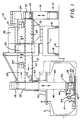
- a cargo handling system is indicated generally by the numeral 10 in Fig. 1.
- a cargo handling system 10 is positioned on a quay (Q) to facilitate loading and unloading a cargo shipping vessel (V).
- the cargo handling system 10 basically includes a portal frame 11 which can travel along the quay (Q) using suitable travel drives 12, known in the art.
- a fixed bridge structure 13 is carried on portal frame 11. On the dock side of fixed bridge structure 13 is located a dockside elevator 14 as will be discussed more fully hereinbelow.
- rotating boom structure 15 constitutes an operable extension of fixed bridge structure 13 for purposes of handling the cargo.
- a shipside elevator 16 is mounted at the distal end of boom structure 15 for movement therewith.
- the cargo handling system 10 is suitable for selective positioning relative to the vessel (V) with which it is being used; and more specifically it is positionable with respect to the particular holds of the vessel (V).
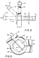
- the mobility of the cargo handling system 10 is derived from travel drives 12 which enable the cargo handling system 10 to be positioned along the quay (Q) and by rotating boom structure 15 which swings outward from the quay (Q) to position shipside elevator 16 relative to a hatch opening (H) of the vessel (V) as depicted in Fig. 2.
- boom structure 15 in its stored position (I), shown in solid lines. Such a position permits cargo vessels to be docked and moored alongside the quay (Q) free of any obstruction by the cargo handling system 10.
- boom structure 15 may be swung outward from its stored position (I) to a partially extended position (II) or a fully extended position (III), each depicted in broken lines in Fig. 2, as necessary to align shipside elevator 16 over a desired hatch opening.
- Another aspect of the cargo handling system 10 which should be appreciated is the fact that it provides protection to the cargo against weather.
- the respective cargo passageways of bridge structure 13, dockside elevator 14, boom structure 15 and shipside elevator 16 all are enclosed with protective material.
- protective material is well known in the art and may include structural metal, or similar building material.
- fixed bridge structure 13 houses a pair of trackways, designated as lower bridge trackway 20 and upper bridge trackway 21. These trackways, 20 and 21, communicate at one end with dockside elevator 14 and at the other end with corresponding lower boom trackway 22 and upper boom trackway 23, respectively, housed within boom structure 15.
- the foregoing network of trackways constitute a portion of the material handling passageways of the cargo handling system 10, and are suitably configured to permit travel of cargo cars 24 therethrough.
- each trackway 21 and 23 includes a guide rail, 25 and 26, respectively, to guide cargo cars 24, as will be more fully discussed hereinbelow.
- a rotatable platform 30 interfaces between bridge trackway 21 and boom trackway 23 and includes a platform rail 31.
- Rotatable platform 30 serves to accept a cargo car 24 for one trackway, for example bridge trackway 21, and then align it with the other trackway, boom trackway 23, so as to permit cargo car 24 to continue onward, as will be discussed hereinbelow.
- Rotatable platform 30 is particularly useful whenever boom structure 15 is not aligned with bridge structure 13.
- Flexible wall members 32 serve to enclose rotating platform 30 to facilitate weatherproofing. The nature of wall members 32 permit substantially unrestricted movement of boom structure 15 relative to bridge structure 13.
- Dockside elevator 14 provides a means for moving cargo cars 24 between the bridge structure 13 and the quay level (Q) as depicted in Fig. 1. Specifically, a carrier 33 travels within dockside elevator 14 carrying cargo cars 24 between either lower bridge trackway 20 or upper bridge trackway 21 and the quay (Q). Suitable sensors and controllers, known in the art, are provided to stop carrier 33 at the appropriate locations to receive or discharge cargo cars 24.
- shipside elevator 16 provides a means in the form of a carrier 34 for moving cargo cars 24 between rotating boom structure 15 and the cargo hold of the vessel (V).
- the housing 35 of shipside elevator 16 does not extend down to the lowermost limit of travel of carrier 34. Rather, housing 35 terminates above the uppermost deck of the vessel (V).
- the lowermost travel of carrier 34 is defined by a work station 36 which may be lowered from housing 35 into the cargo hold of the vessel (V).
- work station 36 is lowered, and supported by, suitable cables or ropes 40. These may be affixed to the four lower corners of work station 36 and operatively connected to suitable winches to raise and lower work station 36 as desired.
- Work station 36 preferably has a cubical framework 41 with a pair of foldable platforms 42 and 43, respectively, mounted on opposite sides thereof. Platforms 42 and 43 are suitably configured to support cargo cars 24 when extended, and to fold upright into framework 41 to provide a compact assembly while work station 36 is maneuvered through a hatch opening (H).
- work platforms 42 and 43 may be extended to facilitate handling of cargo, as will be appreciated hereinbelow.
- Work station 36 also may be provided with at least one suitable jib crane structure 44, which preferably is mounted so as to be foldable against framework 41.
- Jib crane 44 provides suitable means to facilitate handling of cargo, as will be discussed hereinbelow.
- Carrier 34 is moved between work station 36 and lower boom trackway 22 or upper boom trackway 23 as desired using suitable cables or ropes 45 operatively connected to suitable winches. As with dockside elevator 14, suitable sensors and controllers are provided to stop carrier 34 at the appropriate locations to receive or discharge cargo cars 24.
- cables 40 of work station 36 as guides for carrier 34.
- cables 40 may be passed through suitable guide openings in carrier 34 such that carrier 34 may slide freely therealong. Cables 40 are maintained taunt against the weight of work station 36 to provide adequate guidance for carrier 34.
- work station cables 40 and carrier cables 45 are operatively connected to suitable winches.
- winches may preferably be located in a machinery house 46 remote from shipside elevator 16, as depicted in Fig. 1.
- machinery house 46 preferably is located diametrically opposite therefrom about the fulcrum point defined by the centerline of rotation of boom structure 15. In such fashion, boom structure 15 and shipside elevator 16 may handle greater cargo loads without exceeding the safe working limits of the structures.
- Shipside elevator 16 may carry, about the lower end of housing 35, a hatch cover 50 suitable for being placed over the hatch opening (H) of the vessel (V) while the cargo with the hold is being handled.
- Hatch cover 50 is useful to maintain the weatherproof integrity of the cargo handling system 10 by shielding the cargo hold from inclement weather during loading and unloading processes. Hatch cover 50 also is useful when refrigerated cargo is being handled as it facilitates maintaining the low temperature within the refrigerated hold.
- Hatch cover 50 is suitably mounted to housing 35 such that it is freely adjustable vertically as depicted in Fig. 1. In this fashion, hatch cover 50 may be fully raised to permit freedom of movement of boom structure 15 as it swings over the cargo vessel (V). Furthermore, as the cargo vessel (V) is loaded or unloaded the displacement thereof in the water may change and the vertical movability of hatch cover 50 assures proper securement thereof over the hatch opening (H) throughout the cargo handling process.
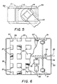
- hatch cover 50 is rotatable about housing 35 and also is expandable, as depicted in Fig. 5. Such mobility enables hatch cover 50 to be usable on many different size hatch openings (H) and when boom structure 15 is oriented at different angles over the vessel (V).
- the present invention heretofore described provides a structure ideally suited for efficiently handling cargo in a weatherproof environment.
- cargo cars 24 Specifically a plurality of cargo cars 24 are utilized to transport the cargo through the system.
- These cargo cars 24 may be designed primarily to travel in a straight line and can be driven using a mechanical drive system independent of cargo cars 24.
- each cargo car 24 be substantially self-contained with its own drive system utilizing an on board power source, such as batteries, or an external power source, such as an electrified collector system.
- cargo cars 24, specifically the movement thereof throughout the system be controlled and tracked using a suitable programmable logic controller system. In this manner, the unmanned cargo cars 24 may be properly controlled at all times.
- each cargo car 24 provides the structural framework to support and move a load of cargo.
- the travel drive assembly provides the means for moving cargo car 24 from one location to another.
- the wheels 51 are driven by a suitable drive motor 52 and gear train assembly 53.
- Guide roller assemblies 54 are located at each end of cargo car 24 to engage the guide rail system, as for example bridge guide rail 26, to assure proper guidance at all times during movement of cargo car 24 throughout the cargo handling system 16.
- an emergency stop system should be provided to prevent collisions with adjacent cars or any unplanned obstruction.
- Such an emergency stop system may employ a safety bumper rail 55 on each end of cargo car 24 which is integrated with the drive system so as to stop movement of cargo car 24 immediately whenever bumper rail 55 contacts an obstruction, so that the body 56 of cargo car 24 does not contact the obstruction.
- Pallet supports 57 are provided along the top surface of body 56. These supports 57 are suitably arranged in such a manner as to permit easy access of standard forklift tines from all sides while maintaining adequate support for the load. It also may be preferable to provide adequate depth between pallet supports 57 to permit insertion of special load handling devices which may be used during the handling process.
- the cargo handling system 10 may have suitable position sensors mounted throughout the cargo car path. Such position sensors indicate and confirm the location of each cargo cars 24 at all times. Similarly, slow down sensors, stop sensors and start sensors may be located at each end of cargo car 24 to slow, stop and start, respectively, cargo car 24 at appropriate locations as designated by the programmable logic control system. Of course, if desired, operation of cargo cars 24, and the cargo handling system 10 overall, may be controlled manually. The use of a suitable logic controller, however, which currently are available in the art, frees the system to act somewhat automatically and provides for a more efficient handling of cargo with the cargo handling system 10.
- the cargo handling system 10 as heretofore discussed may be more fully understood and appreciated by considering the operation of the same in conjunction with the unloading of a cargo vessel (V) which has been moored to the quay (Q) on which the cargo handling system 10 is located.
- Shipside elevator 16 is positioned over an open hatch (H) by maneuvering portal frame 11 and boom structure 15.
- Hatch cover 50 is lowered onto the deck so as to close the hatch (H) and protect the contents of the hold from weather elements.
- Cargo cars 24 are released in the system 10 from the designated temporary storage areas on bridge trackways 20 and 21. Specifically, cargo cars 24 which are located on upper bridge trackway 21 are loaded onto carrier 33 of dockside elevator 14 which lowers them to, and discharges them onto, lower bridge trackway 20. Cargo cars 24 then travel to rotatable platform 30 which aligns the cargo cars 24 with lower boom trackway 22, where they proceed to shipside elevator 16.
- work station 36 is lowered into the cargo hold via cables 40. As the hold generally may be filled with palletized cargo, work station 36 is suspended immediately above the top of the cargo. Work platforms 42 and/or 43 are extended outward and work station 36 is ready to begin transporting cargo.
- Carrier 34 receives a cargo car 24 from lower boom trackway 22 and lowers it down to work station 36 where it moves outward onto one of the platforms 42. Carrier 34 returns to lower boom trackway 22 to receive and lower another cargo car 24.
- the first cargo car 24 on platform 42 may be loaded using jib crane 44 to lift the cargo from the hold and set it onto cargo car 24.
- the next cargo car 24 has been lowered to work station 36 and moved out onto platform 43 for loading.
- the loaded cargo car 24 is moved onto carrier 34 which raises it to upper boom trackway 23 where the cargo car 24 is discharged.
- Carrier 34 then proceeds downward to lower boom trackway 22 to receive an empty cargo car 24 to transport down to work station 36, thereby continuing the cycle.
- the loaded cargo car 24 which is discharged onto upper boom trackway 23 proceeds to rotatable platform 30 where it is aligned with upper bridge trackway 21.
- the loaded cargo car 24 proceeds therealong to be received by carrier 33 of dockside elevator 14 which lowers it down to a transfer station which permits unloading the cargo car and/or cargo for subsequent handling outside of the system 10.
- Carrier 33 then returns empty cargo car 24 to lower bridge trackway 20 thereby continuing the material handling process.
- work station 36 As more cargo is unloaded from the hold, work station 36 continually is lowered until it rests on the inner deck of the hold. When sufficient cargo has been removed from the hold, forklift trucks (F) may be carried into the hold from the quay (Q) via empty cargo cars 24 to facilitate handling of cargo within the hold and to load cargo cars 24 at work station 36.
- forklift trucks (F) may be carried into the hold from the quay (Q) via empty cargo cars 24 to facilitate handling of cargo within the hold and to load cargo cars 24 at work station 36.
- work station 36 provides a highly maneuverable platform to facilitate handling of cargo. Indeed, it may continually be repositioned, vertically and horizontally within the hold to accommodate the workers handling the cargo therein.
- the cargo handling system 10 When the cargo handling system 10 achieves a consistent operating rythm -- loaded and unloaded cargo cars 24 are moving consistently through the system -- efficient cargo handling is achieved. Indeed, the cargo handling system 10, with four forklift trucks (F) operating within the hold of the vessel (V), is capable of moving one cargo car load per minute from the hold. Such capacity generally is accomplished when the system utilizes the aforesaid programmable logic control system to monitor and control the position and movement of the cargo cars 24, carriers 33 and 34, and work station 36.
Landscapes
- Engineering & Computer Science (AREA)
- Mechanical Engineering (AREA)
- Ocean & Marine Engineering (AREA)
- Aviation & Aerospace Engineering (AREA)
- Ship Loading And Unloading (AREA)
- Handcart (AREA)
- Forklifts And Lifting Vehicles (AREA)
- Bridges Or Land Bridges (AREA)
Claims (19)
- Installation de transport de marchandises entre une zone de stockage (Q) et un transporteur (V), comprenant un dispositif (13, 15) à pont disposé entre la zone de stockage (Q) et le transporteur (V), un premier dispositif élévateur (14) placé à partir d'une première extrémité du dispositif à pont (13, 15) à proximité de la zone de stockage (Q), un second dispositif élévateur (16) placé à l'autre extrémité du dispositif à pont (13, 15) et destiné à être positionné par rapport au transporteur (V), le second dispositif élévateur (16) comprenant un dispositif à boîtier (35) communiquant avec un dispositif à chemins (20-23) placé le long du dispositif à pont (13, 15) et raccordant les premier et second dispositifs élévateurs (14, 16), le second dispositif élévateur (16) comportant aussi un poste de travail (36) qui peut être descendu à partir du dispositif à boîtier (35), et un dispositif à véhicules indépendants (24) destiné à transporter les marchandises, le dispositif à véhicules (24) étant mobile sur le premier ou le second dispositif élévateur (14, 16) ainsi que le long du dispositif à chemins (20-23), caractérisée par le montage d'un dispositif de couverture (50) supporté par le dispositif à boîtier (35), le dispositif de couverture (50) étant mobile en hauteur par rapport au dispositif à boîtier (35) et pouvant tourner autour de celui-ci de manière que le dispositif de couverture (50) recouvre une partie au moins des marchandises transportées.
- Installation selon la revendication 1, comprenant en outre un dispositif à châssis (11) mobile par rapport à la zone de stockage (Q), le dispositif à pont (13, 15) étant supporté par le dispositif à châssis (11).
- Installation selon la revendication 1, dans laquelle le dispositif à pont (13, 15) comporte une structure de pont (13) et une structure de flèche (15) mobile par rapport à la structure de pont.
- Installation selon la revendication 3, comprenant en outre un dispositif à châssis (11) mobile par rapport à la zone de stockage (Q), la structure à pont (13) étant supportée par le dispositif à châssis (11).
- Installation selon la revendication 3 ou 4, dans laquelle le premier dispositif élévateur (14) est supporté par la structure à pont (13) et le second dispositif élévateur (16) est supporté par la structure à flèche (15).
- Installation selon la revendication 5, dans laquelle le dispositif à chemins (20-23) comporte une chemin (20, 21) de pont placée le long de la structure à pont (13) et une chemin de flèche (22, 23) placée le long de la structure à flèche (15).
- Installation selon la revendication 6, comprenant en outre un dispositif (30) à plate-forme disposé entre la structure à pont (13) et la structure à flèche (15) afin qu'il présente une interface entre le chemin (20, 21) du pont et le chemin (22, 23) de la flèche.
- Installation selon la revendication 7, dans laquelle le chemin (20, 21) du pont comprend une voie supérieure (21) et une voie inférieure (20), et le chemin (22, 23) de la flèche comprend une voie supérieure (23) et une voie inférieure (22), le dispositif à plate-forme (30) faisant communiquer la voie supérieure (21) du chemin (20, 21) de pont avec la voie supérieure (23) du chemin (22, 23) de flèche, le dispositif à plate-forme (30) faisant en outre communiquer la voie inférieure (20) du chemin (20, 21) du pont avec la voie inférieure (22) du chemin (22, 23) de la flèche.
- Installation selon l'une quelconque des revendications précédentes, dans laquelle le second dispositif élévateur (16) comporte en outre un transporteur (34) destiné à déplacer les véhicules (24) entre le dispositif à chemins (20-23) et le poste de travail (36).
- Installation selon l'une quelconque des revendications précédentes, dans laquelle le dispositif à véhicules (24) comprend des dispositifs d'entraînement indépendants destinés à déplacer le dispositif à véhicules (24) le long du dispositif à chemins (20-23).
- Installation selon l'une quelconque des revendications précédentes, comprenant en outre un dispositif (25, 26, 54) de réglage de la position du dispositif à véhicules (24).
- Installation selon la revendication 11, dans laquelle le dispositif de réglage (25, 26, 54) comporte un dispositif à rails (25, 26) placé le long du dispositif à chemins (20-23), le dispositif à véhicules (24) étant guidé le long du dispositif à rails (25, 26).
- Installation selon la revendication 11 ou 12, dans laquelle le dispositif de réglage (25, 26, 54) comporte un dispositif destiné à régler la vitesse du dispositif à véhicules (24).
- Installation selon la revendication 13, dans laquelle le dispositif destiné à régler la vitesse comprend des capteurs placés sur le dispositif à véhicules (24) et destinés à détecter les obstacles sur le trajet du dispositif à véhicules (24).
- Installation élévatrice destinée au transport de marchandises entre un niveau supérieur et un niveau inférieur, comprenant un dispositif à boîtier (35) placé en position fixe par rapport au niveau supérieur, un poste de travail (36) qui peut être descendu à partir du dispositif à boîtier (35) vers le niveau inférieur, un dispositif (40) de support du poste de travail (36) par rapport au niveau inférieur, et un dispositif transporteur (34) mobile entre le dispositif à boîtier (35) et le poste de travail (36) afin qu'il transporte les marchandises entre les niveaux supérieur et inférieur, caractérisée par la présence d'un dispositif de couverture (50) supporté par le dispositif à boîtier (35), le dispositif de couverture (50) étant mobile verticalement en rotation par rapport au dispositif à boîtier (35).
- Installation élévatrice selon la revendication 15, dans laquelle le poste de travail (36) comporte au moins un dispositif à plate-forme (42, 43) qui peut avancer par rapport au poste pour la réception de marchandises.
- Installation élévatrice selon la revendication 15 ou 16, dans laquelle le poste de travail (36) comporte en outre un dispositif à grue (44) destiné à la manutention des marchandises.
- Installation élévatrice selon l'une quelconque des revendications 15 à 17, dans laquelle le dispositif transporteur (34) coopère de manière coulissante avec le dispositif de support (40).
- Installation élévatrice selon l'une quelconque des revendications 15 à 18, dans laquelle le dispositif de support (40) comporte plusieurs dispositifs (40) à câble souple.
Applications Claiming Priority (3)
| Application Number | Priority Date | Filing Date | Title |
|---|---|---|---|
| US117545 | 1987-11-06 | ||
| US07/117,545 US4897012A (en) | 1987-11-06 | 1987-11-06 | Cargo handling system |
| PCT/US1988/003574 WO1989004286A1 (fr) | 1987-11-06 | 1988-10-17 | Systeme de manutention de cargaison |
Publications (3)
| Publication Number | Publication Date |
|---|---|
| EP0366730A4 EP0366730A4 (fr) | 1990-03-08 |
| EP0366730A1 EP0366730A1 (fr) | 1990-05-09 |
| EP0366730B1 true EP0366730B1 (fr) | 1994-06-22 |
Family
ID=22373503
Family Applications (1)
| Application Number | Title | Priority Date | Filing Date |
|---|---|---|---|
| EP88909896A Expired - Lifetime EP0366730B1 (fr) | 1987-11-06 | 1988-10-17 | Systeme de manutention de cargaison |
Country Status (10)
| Country | Link |
|---|---|
| US (1) | US4897012A (fr) |
| EP (1) | EP0366730B1 (fr) |
| AT (1) | ATE107602T1 (fr) |
| AU (1) | AU2627888A (fr) |
| CA (1) | CA1306437C (fr) |
| DE (1) | DE3850397D1 (fr) |
| ES (1) | ES2013809A6 (fr) |
| MX (1) | MX168994B (fr) |
| NZ (1) | NZ226852A (fr) |
| WO (1) | WO1989004286A1 (fr) |
Families Citing this family (26)
| Publication number | Priority date | Publication date | Assignee | Title |
|---|---|---|---|---|
| AT392253B (de) * | 1989-02-02 | 1991-02-25 | Jonke Hans Dipl Ing Dr Techn | Krananlage mit stetigem foerdersystem fuer den stueckguttransport |
| DE69021417T2 (de) * | 1989-03-20 | 1996-04-04 | Hitachi Elevator Eng | Personenbeförderungseinrichtung. |
| EP0407643A1 (fr) * | 1989-07-14 | 1991-01-16 | COPLA FÖRDER-UND LAGERTECHNIK GESELLSCHAFT FÜR ANLAGENBAU mbH | Appareil pour le chargement et déchargement, en particulier de navires avec une charge isolée et/ou des palettes chargées |
| DE4233726A1 (de) * | 1992-04-23 | 1993-10-28 | Orenstein & Koppel Ag | Verfahren zum Be- und Entladen von Materialien in und aus umschlossenen Räumen sowie Einrichtung zur Abdeckung oder Luken von umschlossenen Räumen |
| DE4307254A1 (de) * | 1993-03-08 | 1994-09-15 | Tax Ingenieurgesellschaft Mbh | Lastenverladekran |
| NO303933B1 (no) * | 1994-02-11 | 1998-09-28 | Tts Dr Bak As | FremgangsmÕte og anlegg for transport av st°rre enheter |
| NL194669C (nl) * | 1994-03-11 | 2002-11-04 | Tts Mongstad As | Stelsel voor het laden en lossen van vrachteenheden in vrachtvaartuigen. |
| US5869178A (en) * | 1994-08-25 | 1999-02-09 | The University Of North Carolina At Chapel Hill | Pultruded fiber-reinforced plastic and related apparatus and method |
| SE508472C2 (sv) * | 1996-07-09 | 1998-10-12 | Wiab Widholms Ind Ab | Mobil godshanteringsenhet |
| US6077019A (en) * | 1997-07-11 | 2000-06-20 | Margaret A. Corcoran | Cargo container storage and retrieval system and method |
| KR100306296B1 (ko) * | 1999-02-20 | 2001-09-24 | 한만엽 | 순환식 트롤리를 갖는 갠트리크레인 |
| US6842665B2 (en) | 2000-12-21 | 2005-01-11 | James P. Karlen | Stowage and retrieval system |
| FI111529B (fi) * | 2001-02-05 | 2003-08-15 | Marine Consulting Suksi Ltd Oy | Siirettävä lastaus-/purkauslaitteisto kappaletavaraa varten |
| NL1020380C2 (nl) * | 2002-04-12 | 2003-03-07 | Wagenborg Shipping B V | Laadinrichting. |
| SE530819E (sv) * | 2005-01-21 | 2016-08-30 | Macgregor (Swe) Ab | Lasthanteringsanordning vid lastfartyg |
| US7815031B2 (en) * | 2006-03-02 | 2010-10-19 | Agile Systems, Inc. | Directional cell indexing matrix |
| WO2008091586A1 (fr) * | 2007-01-22 | 2008-07-31 | Bae Systems Land & Armaments Lp | Système de stockage |
| US20100183407A1 (en) * | 2009-01-21 | 2010-07-22 | Tai-Up Kim | Container transfer port system |
| BR102013022724B1 (pt) * | 2013-09-05 | 2021-08-31 | Carmine Alexandre Cifelli | Equipamento e método para a movimentação de contêineres |
| EP3334676A1 (fr) * | 2015-08-11 | 2018-06-20 | Otis Elevator Company | Système d'ascenseur multi-cabines configurable |
| WO2017027503A1 (fr) * | 2015-08-12 | 2017-02-16 | Otis Elevator Company | Système de transport pour cage d'ascenseur sans câble et procédé |
| US9598265B1 (en) * | 2015-09-28 | 2017-03-21 | Smart Lifts, Llc | Vertically and horizontally mobile elevator cabins |
| CN106927336A (zh) * | 2017-03-22 | 2017-07-07 | 山东建筑大学 | 一种面向双井道可水平和垂直运行的电梯 |
| BR102017014425B1 (pt) * | 2017-07-03 | 2020-06-16 | Vale S/A | Dispositivo para carregamento de navios graneleiros e método de carregamento |
| SE542919C2 (en) * | 2019-01-16 | 2020-09-15 | Scania Cv Ab | Method and control device for assembling a vehicle |
| CN118004787A (zh) * | 2024-03-11 | 2024-05-10 | 江南造船(集团)有限责任公司 | 一种船舶岸船货物运输系统及运输方法 |
Family Cites Families (22)
| Publication number | Priority date | Publication date | Assignee | Title |
|---|---|---|---|---|
| DE304711C (fr) * | ||||
| US691719A (en) * | 1901-06-08 | 1902-01-21 | John L Adams | Balloon-observatory. |
| US1525950A (en) * | 1922-05-05 | 1925-02-10 | Arthur T Prescott | Cargo-handling apparatus |
| US2572165A (en) * | 1947-06-19 | 1951-10-23 | John N Locki | Floating hoist |
| GB706559A (en) * | 1950-06-01 | 1954-03-31 | Virgilio Spallarossa | Improvements in or relating to loading, discharging and reloading of goods during wet or adverse atmospheric conditions |
| FR1031730A (fr) * | 1950-12-18 | 1953-06-25 | Anciens Etablissements Noe L A | Perfectionnements apportés aux transporteurs à poches pour le déchargement des bateaux de régimes de bananes ou de colis de denrées demandant des soins analogues |
| GB1219574A (en) * | 1967-03-31 | 1971-01-20 | Fedde Walda | A container ship and a process for loading and unloading same |
| US3520396A (en) * | 1968-03-26 | 1970-07-14 | Rudolf Geisel Mas Fab | Load handling devices |
| GB1236247A (en) * | 1968-10-07 | 1971-06-23 | Mavor & Coulson Ltd | A gantry for material handling apparatus |
| US3630390A (en) * | 1969-02-07 | 1971-12-28 | Hans Tax | Container-loading crane arrangement |
| NL7000818A (fr) * | 1970-01-21 | 1971-07-23 | ||
| JPS5141273B1 (fr) * | 1970-12-30 | 1976-11-09 | ||
| US3814211A (en) * | 1972-03-01 | 1974-06-04 | Mcneil Corp | Air space vehicle servicing apparatus |
| JPS4899880A (fr) * | 1972-03-31 | 1973-12-17 | ||
| SE382799B (sv) * | 1974-02-27 | 1976-02-16 | Mitsui Shipbuilding Eng | Sett for containerhantering pa en containeruppstellningsplats |
| SU627011A1 (ru) * | 1976-02-16 | 1978-10-05 | Предприятие П/Я А-3780 | Устройство дл передачи людей и грузов в море с судна на судно |
| SE419325B (sv) * | 1976-06-11 | 1981-07-27 | Resmastservice Ab | Sett for att lasta och lossa tunga kollin pa fartyg samt anordning for settets genomforande |
| US4172685A (en) * | 1976-10-22 | 1979-10-30 | Hitachi, Ltd. | Method and apparatus for automatic operation of container crane |
| JPS5531777A (en) * | 1978-08-30 | 1980-03-06 | Hitachi Ltd | Material handling apparatus for containers |
| SU796130A1 (ru) * | 1979-03-22 | 1981-01-15 | Дальневосточный Филиал Государственногопроектно-Изыскательского И Научно- Исследовательского Института Морскоготранспорта | Портовый перегружатель дл перегрузкигРузОВ B изОлиРОВАННОй СРЕдЕ |
| EP0025105B1 (fr) * | 1979-08-02 | 1984-06-06 | Toniolo, Alberto, Dott. ing. | Elévateur pour la manutention de containers, en particulier dans des ports |
| JPS60151194A (ja) * | 1984-01-18 | 1985-08-09 | Ishikawajima Harima Heavy Ind Co Ltd | 荷役装置 |
-
1987
- 1987-11-06 US US07/117,545 patent/US4897012A/en not_active Expired - Fee Related
-
1988
- 1988-10-17 EP EP88909896A patent/EP0366730B1/fr not_active Expired - Lifetime
- 1988-10-17 AU AU26278/88A patent/AU2627888A/en not_active Abandoned
- 1988-10-17 AT AT88909896T patent/ATE107602T1/de not_active IP Right Cessation
- 1988-10-17 WO PCT/US1988/003574 patent/WO1989004286A1/fr not_active Ceased
- 1988-10-17 DE DE3850397T patent/DE3850397D1/de not_active Expired - Lifetime
- 1988-10-26 CA CA000581311A patent/CA1306437C/fr not_active Expired - Lifetime
- 1988-11-03 MX MX013649A patent/MX168994B/es unknown
- 1988-11-04 ES ES8803377A patent/ES2013809A6/es not_active Expired - Lifetime
- 1988-11-04 NZ NZ226852A patent/NZ226852A/en unknown
Also Published As
| Publication number | Publication date |
|---|---|
| MX168994B (es) | 1993-06-16 |
| ATE107602T1 (de) | 1994-07-15 |
| US4897012A (en) | 1990-01-30 |
| ES2013809A6 (es) | 1990-06-01 |
| WO1989004286A1 (fr) | 1989-05-18 |
| EP0366730A4 (fr) | 1990-03-08 |
| CA1306437C (fr) | 1992-08-18 |
| DE3850397D1 (de) | 1994-07-28 |
| AU2627888A (en) | 1989-06-01 |
| EP0366730A1 (fr) | 1990-05-09 |
| NZ226852A (en) | 1990-04-26 |
Similar Documents
| Publication | Publication Date | Title |
|---|---|---|
| EP0366730B1 (fr) | Systeme de manutention de cargaison | |
| US3807582A (en) | Loading and unloading device for ship containers | |
| US3598440A (en) | Rotatable container-hoisting apparatus | |
| KR100719031B1 (ko) | 아이에스오 컨테이너용 선적 장치 | |
| US4750429A (en) | Transportation systems | |
| SU1711666A3 (ru) | Конвейерное устройство дл загрузки и разгрузки грузов из судов | |
| FI79510B (fi) | Kajkran och saett foer flyttning av last mellan fartyg och kaj. | |
| US5039275A (en) | Method for transferring cargo between vessel and dock | |
| US6068435A (en) | Goods handling system | |
| WO2024207029A2 (fr) | Système de stockage et de distribution pour conteneurs | |
| US4138961A (en) | Vessel for carrying steel slabs | |
| JPH04327430A (ja) | 船への積込・積降方法及びその装置 | |
| US4610594A (en) | Container conveyor system | |
| US4946344A (en) | General cargo crane | |
| US6648571B1 (en) | Mobile handling apparatus for loading and unloading ships in docks | |
| JPH10194461A (ja) | 内航用コンテナ専用船の荷役設備 | |
| CA1324347C (fr) | Systeme de manutention monovoie pour charges partielles | |
| JPH026057Y2 (fr) | ||
| US3330427A (en) | Barge loading crane and method | |
| WO2025208025A1 (fr) | Système de stockage de grille avec unité de transfert automatique (atu) de grille suspendue | |
| JPS6312592A (ja) | コンテナ移載装置 | |
| JPH07330169A (ja) | 小型コンテナ船用荷役設備 | |
| WO2011046259A1 (fr) | Dispositif de transfert de conteneur par rails | |
| JPH0233032A (ja) | 船舶と波止場間の貨物移送装置および方法 | |
| JPH04350212A (ja) | ボート搬送揚降装置 |
Legal Events
| Date | Code | Title | Description |
|---|---|---|---|
| PUAI | Public reference made under article 153(3) epc to a published international application that has entered the european phase |
Free format text: ORIGINAL CODE: 0009012 |
|
| 17P | Request for examination filed |
Effective date: 19890707 |
|
| AK | Designated contracting states |
Kind code of ref document: A1 Designated state(s): AT DE GB NL |
|
| 17Q | First examination report despatched |
Effective date: 19911014 |
|
| GRAA | (expected) grant |
Free format text: ORIGINAL CODE: 0009210 |
|
| AK | Designated contracting states |
Kind code of ref document: B1 Designated state(s): AT DE GB NL |
|
| PG25 | Lapsed in a contracting state [announced via postgrant information from national office to epo] |
Ref country code: NL Effective date: 19940622 Ref country code: AT Effective date: 19940622 |
|
| REF | Corresponds to: |
Ref document number: 107602 Country of ref document: AT Date of ref document: 19940715 Kind code of ref document: T |
|
| REF | Corresponds to: |
Ref document number: 3850397 Country of ref document: DE Date of ref document: 19940728 |
|
| PG25 | Lapsed in a contracting state [announced via postgrant information from national office to epo] |
Ref country code: DE Effective date: 19940923 |
|
| PG25 | Lapsed in a contracting state [announced via postgrant information from national office to epo] |
Ref country code: GB Effective date: 19941017 |
|
| NLV1 | Nl: lapsed or annulled due to failure to fulfill the requirements of art. 29p and 29m of the patents act | ||
| PLBE | No opposition filed within time limit |
Free format text: ORIGINAL CODE: 0009261 |
|
| STAA | Information on the status of an ep patent application or granted ep patent |
Free format text: STATUS: NO OPPOSITION FILED WITHIN TIME LIMIT |
|
| 26N | No opposition filed | ||
| GBPC | Gb: european patent ceased through non-payment of renewal fee |
Effective date: 19941017 |