EP0366800A1 - Méthode pour empêcher la perte de toner durant le transport d'une nouvelle unité de développement avant son installation - Google Patents
Méthode pour empêcher la perte de toner durant le transport d'une nouvelle unité de développement avant son installation Download PDFInfo
- Publication number
- EP0366800A1 EP0366800A1 EP89902291A EP89902291A EP0366800A1 EP 0366800 A1 EP0366800 A1 EP 0366800A1 EP 89902291 A EP89902291 A EP 89902291A EP 89902291 A EP89902291 A EP 89902291A EP 0366800 A1 EP0366800 A1 EP 0366800A1
- Authority
- EP
- European Patent Office
- Prior art keywords
- toner
- developing
- developing unit
- cartridge
- section
- Prior art date
- Legal status (The legal status is an assumption and is not a legal conclusion. Google has not performed a legal analysis and makes no representation as to the accuracy of the status listed.)
- Granted
Links
Images


Classifications
-
- G—PHYSICS
- G03—PHOTOGRAPHY; CINEMATOGRAPHY; ANALOGOUS TECHNIQUES USING WAVES OTHER THAN OPTICAL WAVES; ELECTROGRAPHY; HOLOGRAPHY
- G03G—ELECTROGRAPHY; ELECTROPHOTOGRAPHY; MAGNETOGRAPHY
- G03G15/00—Apparatus for electrographic processes using a charge pattern
- G03G15/06—Apparatus for electrographic processes using a charge pattern for developing
- G03G15/08—Apparatus for electrographic processes using a charge pattern for developing using a solid developer, e.g. powder developer
- G03G15/0896—Arrangements or disposition of the complete developer unit or parts thereof not provided for by groups G03G15/08 - G03G15/0894
-
- G—PHYSICS
- G03—PHOTOGRAPHY; CINEMATOGRAPHY; ANALOGOUS TECHNIQUES USING WAVES OTHER THAN OPTICAL WAVES; ELECTROGRAPHY; HOLOGRAPHY
- G03G—ELECTROGRAPHY; ELECTROPHOTOGRAPHY; MAGNETOGRAPHY
- G03G15/00—Apparatus for electrographic processes using a charge pattern
- G03G15/06—Apparatus for electrographic processes using a charge pattern for developing
- G03G15/08—Apparatus for electrographic processes using a charge pattern for developing using a solid developer, e.g. powder developer
- G03G15/0822—Arrangements for preparing, mixing, supplying or dispensing developer
- G03G15/0877—Arrangements for metering and dispensing developer from a developer cartridge into the development unit
- G03G15/0881—Sealing of developer cartridges
- G03G15/0882—Sealing of developer cartridges by a peelable sealing film
-
- G—PHYSICS
- G03—PHOTOGRAPHY; CINEMATOGRAPHY; ANALOGOUS TECHNIQUES USING WAVES OTHER THAN OPTICAL WAVES; ELECTROGRAPHY; HOLOGRAPHY
- G03G—ELECTROGRAPHY; ELECTROPHOTOGRAPHY; MAGNETOGRAPHY
- G03G15/00—Apparatus for electrographic processes using a charge pattern
- G03G15/06—Apparatus for electrographic processes using a charge pattern for developing
- G03G15/08—Apparatus for electrographic processes using a charge pattern for developing using a solid developer, e.g. powder developer
- G03G15/0896—Arrangements or disposition of the complete developer unit or parts thereof not provided for by groups G03G15/08 - G03G15/0894
- G03G15/0898—Arrangements or disposition of the complete developer unit or parts thereof not provided for by groups G03G15/08 - G03G15/0894 for preventing toner scattering during operation, e.g. seals
Definitions
- the present invention relates to a developing unit providing a toner supply section to mount a toner cartridge for supplying toner and an image forming apparatus utilizing the same developing unit.
- An image forming apparatus such as a duplicator or a printer utilizing toner of the electrophotographic system and electrostatic recording system provides a developing apparatus comprising a developing means which supplies toner on a medium and develops an electrostatic latent image formed on the medium and a developing chamber accommodating such developing means and toner to be supplied to the medium from the developing means.
- this developing apparatus is also provided with a cartridge mounting section on which the cartridge accommodating toner therein is mounted and the toner is supplied to the developing chamber via this cartrige.
- the developing apparatus in view of facilitating maintenance and replacing work of the developing apparatus [particularly, the carrier which has passed its life is considered as the object, in case 2-element developer consisting of toner and carrier is used., the developing apparatus as a whole is formed as a unit, as is described in the official gazette of the Japanese Patent Laid-lopen No. 62-17763, for example, and thereby it can be mounted/dismounted to/from the image forming apparatus.
- the present invention constitutes a developing unit for developing a latent image on a medium, comprising a developing means which supplies toner on a medium tc develop latent image, a developing chamber acommodating the developing means and toner, a toner case for encasing toner to be supplied to the developing chamber, a developing toner supply means for supplying the toner to the developing chamber from the toner case, a car ridge mounting section for allowing mounting of cartrige accommodating the toner therein to supply the toner to the toner case and a preventing means which is mounted to the cartridge mounting section during the transportation of developing unit to prevent leak of toner in the developing chamber to the outside of developing unit via the cartridge mounting section.
- the toner is previously encased, before transportation, to the developing chamber of developing unit and a preventing means prepared is mounted to the cartridge mounting section.
- the preventing means perfectly seals the cartridge mounting section and thereby prevents entrance of humidity into the interior. Therefore, solidification of toner in the developing unit can be prevented.
- the developing unit is transported under this condition, but the toner overflowing the developing chamber to the area near the cartridge mounting port (mounting port of preventing means. during the transportation is stopped to spill by the preventing means mounted to the cartridge mounting section and is no longer leak to the outside of unit.
- this preventing means a cylindrical member having an opening is used and in this case the circumferencial position of cylindrical member is determined so that the opening is located at the lower side. Thereby, the overflowing developer enters the cylindrical member passing through the opening. Accordingly, if the preventing means does not perfectly close the cartridge mounting section, namely even if a certain insertion gap exist between the cylindrical member and cartridge mounting section, leak of toner to the outside can be prevented.
- the toner collected in the cylindrical member is generally supplied to the developing chamber by the toner sypply means during operation.
- Fig. 1 illustrates a constitution of an electrophotographic recording apparatus.
- a photosensitive drum 11A is rotatably driven by a rotating motor not illustrated using a belt transmission mechanism to form an image with process members such as a precharger, an exposure optical system, a developing unit, a transcription unit and a cleaner; a precharger 11B uniformly charges the entire part of photosensitive drum ll A ; a laser optical unit 14 forms an electrostatic latent image on the photosensitive drum 11A by utilizing a semiconductor laser, a rotatable polygon mirror and a f-0 lens and driving the semiconductor laser depending on the information to be recorded; a developing unit 15 is removably provided, as described later, and develops an electrostatic latent image on the photosensitive drum 11A with the toner; a transcription unit 13, comprising a transcription charger in the left side in Fig.
- a fixing unit 16 is provided with a thermo roller and a pressurizing roller in order to permanently fixe the toner image on the recording paper.
- a sheet cassette 17 is provided with a supporting plate 114 on which many sheets of cut sheet type recording papers for transcription of toner image are stacked, a spring for energizing upward the supporting plate 114 and a slit 45 for permitting passage of papers fed from the other cassette not illustrated and arranged at the lower stage thereof, and is mounted removably in the left side in the figure.
- a pick roller 27 is provided for feeding papers within the sheet cassette 17; a feed roller 28 for transferring supplied paper through a transfer route 29; a standby roller 30 for permitting a pinch roller 47 provided in the photosensitive drum unit comprising the precharger 11B, cleaner 46 and photosensitive drum 11A to be in contact with pressure therewith and sending papers to the transcription part 31 by being rotatably and synchronously driven by rotation of the photosensitive. drum 11A.
- a pretranscription sheet guide 12 is provided for guiding a paper having passed the standby roller 30 to the transcription part 31.
- This sheet guide is mounted to an arm 20 rotatable around a shaft 19 and can be located to the desired position by being in contact with a stopper 26, by its own weight, provided to the transcription unit 13.
- a sheet guide 32 is provided for guiding papers after image transcription to the fixing unit 16.
- the paper having fixed an image through the fixing unit 16 is guided and transferred along the sheet guide 34 by the transfer rollers 35, 36, 37 and finally ejected on . an exhaust stacker 38.
- the upper frame 41 of the frames divided into the upper and lower frames on the paper transfer route is provided rotatably around the shaft 40 provided to the lower frame 39 and 44, 43 designate paper transfer detection sensors and 42, manual paper inserting port.
- a cleaner consisting, for example, of a far brush to remove the toner remaining on the photosensitive drum llA.
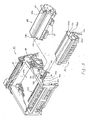
- the upper frame 41 is provided, removably in the axial direction of the photosensitive drum 11A, with a photosensitive drum unit 50, as shown in Fig. 3, comprising a photosensitive drum ll A , a cleaner 46, a precharger 11B and a pinch roller 47.
- the photosensitive drum unit 50 is mounted to the upper frame 41 or can be removed therefrom by being guided along the guide rails 51a, 51b.
- the photosensitive drum 50 after the photosensitive drum 50 is mounted to the upper frame 41, it can be fixed thereto by screwing a screw 52a to a screwing hole 52b.
- the developing unit 15 can also be removably mounted to the upper frame 41 by being guided toward the upper frame 41 along the guide rail 53.
- This removing operation is carried out when the carrier of the double-element developer consisting of the carrier and toner enclosed within the developing unit 15 reaches its life expectancy.
- the guide holes 15al, 15a2, 15a3 bored to a side plate 15a of the developing unit 15 are inserted to the guide pins 54a, 54b, 54c provided in the side of upper frame 41 for positioning.
- the relative positioning of shaft-to- shaft distance between the photosensitive drum 11A and magnet roller in the developing unit 15 is carried out by mutually setting in contact rotatable disks respectively provided to the shafts of a gear fitted to a drive shaft for driving the photosensitive drum 11A and a gear for rotating magnet roller in the developing unit 15.
- the toner is also supplied to this developing unit 15 by mounting a toner catridge of the well known constitution to the toner cartridge case 15b from the opening thereof under the condition that the developing unit 15 is attached to the upper frame 41.
- a laser optical unit 14 is not illustrated and this unit 14 is mounted to the mounting area 41a of upper frame 41. Accordingly, the photosensitive drum 11A is irradiated with the laser beam through the opening 41b provided to the upper frame 41.
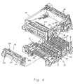
- this upper frame 41 is provided opposed to the lower frame 39 as shown in Fig. 39, and the pinch roller 47, photosensitive drum 11A, pinch roller 35 pressurized in contact with the transfer roller 35 and a protruded part 15b provided at the botton part of developing unit 15 form the upper transfer section, while the standby roller 30, pretransfer sheet guide 12, sheet guide 32 and transfer roller 35 form the lower transfer section.
- the photosensitive drum unit and developing unit 15 are mounted on the upper frame 41 and the toner cartridge can be mounted to the toner cartridge case 15b and removed therefrom under this condition.
- the fixing unit 16 is removably mounted to the lower frame 39. Namely, the fixing unit 16 is positioned to the lower frame 39 with the guide pins 16a, 16b, a couple of screws 55a, 55b provided to the fixing unit 16 are engaged with the screw hole 39x of the lower frame 39 and thereby the fixing unit 16 may be tightened to the lower frame 39.
- Fig. 5 illustrates a constitution of the developing unit described above.
- a developing roller 3 is constituted by a stationarily arranged magnet roller and a rotatable cylindrical sleeve made of nonmagnetic material comprising such magnet roller. With rotation of this sleeve, a magnetic brush is formed by toner and carrier and an electrostatic latent image formed on the photosensitive drum 11A provided opposed to the magnetic brush can be developed.
- the double-element deveoper 100 is composed of toner and carrier and is encased within the developing tank 4 together with the developing roller 3.
- a toner concentration sensor is provided to measure the concentration of toner for the carrier.
- the developing tank 4 also comprises a flow restriction plate 4b which restricts flow of double-element developer 100 restricted by the blades 4a, 4b to restrict height of magnetic brush formed by the developing roller 3 only to the one direction for the width direction of photosensitive drum 11A and a screw- shaped stirring roller 2 which sends the double-element developer 100 in the developing tank 4 in the reverse direction to the flowing direction at the flow restriction plate 4b so that the toner supplied from the toner supply roller described later and the double-element developer 100 falling from the flow restriction plate 4b can be stirred.
- a flow restriction plate 4b which restricts flow of double-element developer 100 restricted by the blades 4a, 4b to restrict height of magnetic brush formed by the developing roller 3 only to the one direction for the width direction of photosensitive drum 11A
- a screw- shaped stirring roller 2 which sends the double-element developer 100 in the developing tank 4 in the reverse direction to the flowing direction at the flow restriction plate 4b so that the toner supplied from the toner supply roller described later and the double-element
- the toner supply section 5 is provided integrally with the developing tank 4 and also comprises a cartridge mounting section 5a on which the toner cartridge described later is mounted and a toner case 5b in which the toner supplied from the toner cartridge mounted on the cartridge mounting section 5a is reserved. Moreover, in the boundary to the developing tank 4 at the lower part of toner supply section 5, is provided a toner supply roller 6 made of a sponge material to supply the toner in the toner case 5b to the developing tank 4. This toner supply roller 6 is intermittently driven (the driving system is not illustrated; and rotated depending on the toner concentration detection result of concentration sensor 7 provided at the bottom of developing tank 4.
- This developing unit 15 is arranged to the predetermined position of the electrophotographic recording apparatus to develop the electrostatic latent image on the photosensitive drum.
- the stirring roller 2 and developing roller 3 are rotated.
- the double-element developer 100 in the developing tank 4 is supplied to the developing roller 3 by the stirring roller 2.
- the developer on the developing roller 3 is carried to the developing position (a) through restriction of height by the doctor blade 4a for the development therein.
- the concentration sensor 7 When the development advances and toner concentration of double-element developer 100 is lowered to the specified value, it is detected by the concentration sensor 7 to rotate the toner supply roller 6.
- the toner in the toner supply section 5 is supplied to the developing tank 4 by the toner supply roller 6 for adjustment of concentration.
- the sensor not illustrated detects this condition, indicating that the toner must be supplied. In this case, toner can be supplied as explained hereunder.
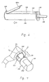
- toner cartridge 110 is for exmaple disclosed in the official gazette of Japanese Device Application No. 62-41325. Namely, the toner is encased within the cylindrical body 120 of toner cartridge 110. An opening 130 formed on the cylindrical body 120 is closed by a sealing member 140. For the supply of toner, the opening l30 is placed upper side and the toner cartridge 110 is inserted from the opening 5Z of toner supply section 5 while removing the sealing member 140. In this case, as shown in Fig.
- a extruded area 150 is provided at the end part of cylindrical body 120 in the side of forming the opening 130 and a recessed area 160 corresponding to such extruded area 150 is also provided at the region near the inlet of toner supply section 5.
- the extruded area 150 is inserted while engagement with the recessed area 160.
- the opening 130 can certainly be placed in the upper side.
- removing of sealing member 140 can be done easily, as shown in Fig. 6, by bending the sealing member 140 and inserting the cartridge 110 while pulling the end 140a of the sealing member 140.
- the cylindrical body 120 Upon insertion of cartridge 110, the cylindrical body 120 is rotated for 180° by operating a handle 180 of the flange 170 provided to the cylindrical body 12. Thereby, the toner in the cartridge drops from the opening 130 and is supplied to the toner case 5b through a connecting port 5y connecting the cartridge mounting section 5a and the toner case 5b.
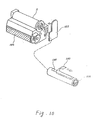
- This developing unit 15 is transported as described hereunder. That is, as shown in Fig. 5, the toner and carrier are sealed within the developing tank 4 of developing unit 15 and meanwhile, the cylindrical member 210 is set to the cartridge mounting section 5a.
- the cylindrical member 210 is constituted integrally with a side plate 230 with the flange, as shown in Fig. 8, at the one end of cylindrical body 220 engaging with the cartridge mounting section 5a of toner supply section 5 and the opening 220 is formed to the cylindrical body 220.
- cylindrical member 210 The application procedures of cylindrical member 210 are as follow.
- This cylindrical member 210 can directly use the cartridge 110 which does not seal the toner therein and is not provided with the sealing member 140.
- the cylindrical member 210 is not always required to be in the same size and shape as the toner cartridge 110 and it is enough when it can cover the hollow section and connecting inlet 5y and has the opening 240 which allow passage of toner sent from the toner case 5b.
- the toner and carrier which are constitutents of double-element developer 100 are encased within the tank 4 before transportation and the prepared cylindrical member 210 is mounted to the cartridge mounting section 5a of the toner supply section 5.
- the position in the circumferencial direction of cylindrical member 210 is set so that the opening 240 is located in the lower side and when the cylindrical member is mounted, as shown in Fig. 8,'the flange 230a of side plate 230 engages with the circumference 50a of toner cartridge mounting port 50a of toner supply section 5 to seal this area.
- the developing unit 15 is housed within the upper and lower styrene cases 101, 102 and the joint of both cases 101, 102 is sealed with a vinyl tape 103 for the packing.
- the exposed area of developing roller 3 and side surface of unit are held by the packings 104 and 105 and moreover aa desiccating agent 106 is put into both cases 101, 102.
- the toner supply section 5 is perfectly sealed to prevent entry of humidity.
- Transportion of unit is carried out under this condition but the developer 100 overflowing to the toner case 5b passing through the gap, during the transportion, between the toner case 5b and toner supply roller 6 from the developing tank 4 is stopped by the cylindrical member 210 mounted to the cartridge mounting section 5a and cannot leak to the outside. Since the opening 240 is provided at the lower side of cylindrical member 210, the overflowing deveoper is collected within the cylindrical member 210 passing through this opening 240. In case the developing unit 15 is to be stored after completion of transportation, the developer 100 in the cylidrical member 210 almost drops into the toner case 5b.
- the developing unit 15 transported and stored as described above can be mounted to the recording apparatus by unpacking and then mounting it to the specified position of the apparatus. While the cylindrical member 210 is mounted, operation can be strated. Thereby, the toner in the toner case 5b can gradually be returned to the developing tank 4 by the toner supply roller 6. Even if a part of developer 100 is remained within the cylindrical member 210 at the time of mounting, the developer 100 dros due to the vibration during the operation thereof and finally returned perfectly to the developing tank 4.
- the toner cartridge can also be used as the cylindrical member.
- the unit is packed using the packing materials 104, 105 for'the purpose of transportation.
Landscapes
- Physics & Mathematics (AREA)
- General Physics & Mathematics (AREA)
- Dry Development In Electrophotography (AREA)
- Electrophotography Configuration And Component (AREA)
Abstract
Applications Claiming Priority (3)
| Application Number | Priority Date | Filing Date | Title |
|---|---|---|---|
| JP63030038A JPH01206376A (ja) | 1988-02-13 | 1988-02-13 | 現像ユニット |
| JP30038/88 | 1988-02-13 | ||
| PCT/JP1989/000131 WO1989007788A1 (fr) | 1988-02-13 | 1989-02-09 | Unite de developpement et appareil de formation d'images l'utilisant |
Publications (3)
| Publication Number | Publication Date |
|---|---|
| EP0366800A1 true EP0366800A1 (fr) | 1990-05-09 |
| EP0366800A4 EP0366800A4 (en) | 1992-08-26 |
| EP0366800B1 EP0366800B1 (fr) | 1995-04-19 |
Family
ID=12292655
Family Applications (1)
| Application Number | Title | Priority Date | Filing Date |
|---|---|---|---|
| EP89902291A Expired - Lifetime EP0366800B1 (fr) | 1988-02-13 | 1989-02-09 | Méthode pour empêcher la perte de toner durant le transport d'une nouvelle unité de développement avant son installation |
Country Status (5)
| Country | Link |
|---|---|
| US (1) | US5153643A (fr) |
| EP (1) | EP0366800B1 (fr) |
| JP (1) | JPH01206376A (fr) |
| DE (1) | DE68922273T2 (fr) |
| WO (1) | WO1989007788A1 (fr) |
Families Citing this family (8)
| Publication number | Priority date | Publication date | Assignee | Title |
|---|---|---|---|---|
| JPH0552863U (ja) * | 1991-12-18 | 1993-07-13 | 株式会社リコー | 現像ユニット等及びトナーカートリッジの着脱機構 |
| JP3004123B2 (ja) * | 1992-05-18 | 2000-01-31 | キヤノン株式会社 | 現像装置 |
| US5307117A (en) * | 1992-12-08 | 1994-04-26 | Xerox Corporation | Protective shipping cover for CRU |
| US5404212A (en) * | 1993-09-24 | 1995-04-04 | Laser Ink Ltd. | Toner cartridge seal |
| TW312700B (fr) * | 1994-05-17 | 1997-08-11 | Sony Co Ltd | |
| AU3426895A (en) * | 1994-10-17 | 1996-05-02 | Canon Kabushiki Kaisha | Toner container, toner container assembling method, process cartridge, and electrophotographic image forming apparatus |
| US9708116B2 (en) | 2012-06-08 | 2017-07-18 | Canon Kabushiki Kaisha | Packing member and cartridge packed in the packing member |
| US9002235B2 (en) * | 2013-02-27 | 2015-04-07 | Hewlett-Packard Development Company, L.P. | Toner cartridge packaging |
Family Cites Families (8)
| Publication number | Priority date | Publication date | Assignee | Title |
|---|---|---|---|---|
| US4060105A (en) * | 1975-09-11 | 1977-11-29 | Xerox Corporation | Toner loading apparatus with replenishing supply container |
| US4274455A (en) * | 1979-04-13 | 1981-06-23 | Tbs, Inc. | Toner loading device |
| JPS606968A (ja) * | 1983-06-27 | 1985-01-14 | Fuji Xerox Co Ltd | 電子写真複写機のトナ−補給装置 |
| JPS61169858A (ja) * | 1985-01-23 | 1986-07-31 | Fuji Xerox Co Ltd | 現像剤補給装置 |
| JPS62209545A (ja) * | 1986-03-11 | 1987-09-14 | Konishiroku Photo Ind Co Ltd | 複写機等の現像装置取付部構造 |
| US4768055A (en) * | 1986-06-17 | 1988-08-30 | Mita Industrial Co., Ltd. | Image forming machine having a toner recycling unit |
| JPS6314187A (ja) * | 1986-07-04 | 1988-01-21 | Sharp Corp | 現像剤回収装置 |
| US4862210A (en) * | 1988-02-25 | 1989-08-29 | Access Computer Products, Inc. | Replaceable seal assembly for toner cartidges and method of use |
-
1988
- 1988-02-13 JP JP63030038A patent/JPH01206376A/ja active Pending
-
1989
- 1989-02-09 EP EP89902291A patent/EP0366800B1/fr not_active Expired - Lifetime
- 1989-02-09 DE DE68922273T patent/DE68922273T2/de not_active Expired - Fee Related
- 1989-02-09 US US07/381,394 patent/US5153643A/en not_active Expired - Lifetime
- 1989-02-09 WO PCT/JP1989/000131 patent/WO1989007788A1/fr not_active Ceased
Also Published As
| Publication number | Publication date |
|---|---|
| DE68922273T2 (de) | 1995-11-16 |
| EP0366800A4 (en) | 1992-08-26 |
| US5153643A (en) | 1992-10-06 |
| JPH01206376A (ja) | 1989-08-18 |
| EP0366800B1 (fr) | 1995-04-19 |
| WO1989007788A1 (fr) | 1989-08-24 |
| DE68922273D1 (de) | 1995-05-24 |
Similar Documents
| Publication | Publication Date | Title |
|---|---|---|
| EP0829778A2 (fr) | Unité de traitement, récipient de développateur, récipient de développateur usé, procédé d'assemblage d'unité de traitement, procédé de remplissage de développateur dans une unité de traitement | |
| US6785497B1 (en) | Toner cartridge and toner supply device | |
| US7272339B2 (en) | Process cartridge including first and second frames and separating member moving the second frame to a separated position and image forming apparatus detachably mounting the cartridge | |
| US6151459A (en) | Development cartridge and image forming apparatus | |
| KR0139824B1 (ko) | 토너 카트리지 | |
| EP1184742B1 (fr) | Appareil de formation d'images et réservoir d'alimentation en développateur amovible | |
| US5289241A (en) | Developing unit for an image forming apparatus having adjoining fresh and waste toner containers | |
| US6070027A (en) | Developing apparatus with auxiliary seal disposed outside of end seal | |
| EP1041453A2 (fr) | Récipient d'alimentation en toner et appareil de formation d'images | |
| US5722020A (en) | Developer container and developer supplying apparatus | |
| EP0366800B1 (fr) | Méthode pour empêcher la perte de toner durant le transport d'une nouvelle unité de développement avant son installation | |
| JPH06186844A (ja) | 現像剤収納容器及び現像剤補給装置 | |
| EP0589777A2 (fr) | Appareil de formation d'images avec unité de traitement pouvant être retirée de l'unité principale de cet appareil | |
| JP2003066704A (ja) | 封止部材及びトナー補給容器及びトナー補給装置 | |
| JP2935667B2 (ja) | 電子写真プロセスの現像装置 | |
| JP2003173076A (ja) | 現像装置および現像カートリッジ | |
| JP6381378B2 (ja) | 現像装置、プロセスカートリッジ及び画像形成装置 | |
| JPH0815971A (ja) | 画像形成装置 | |
| JPH0418578A (ja) | トナーカートリッジ | |
| US5606405A (en) | Developing apparatus and image forming apparatus having developing apparatus | |
| JPH10268641A (ja) | 粉体移送装置 | |
| JPH01296261A (ja) | 画像形成装置及びプロセスカートリッジ | |
| JP3889184B2 (ja) | 電子写真式画像形成装置 | |
| JPH04115273A (ja) | 画像形成装置 | |
| JP2005121764A (ja) | プロセスカートリッジおよび電子写真画像形成装置 |
Legal Events
| Date | Code | Title | Description |
|---|---|---|---|
| PUAI | Public reference made under article 153(3) epc to a published international application that has entered the european phase |
Free format text: ORIGINAL CODE: 0009012 |
|
| 17P | Request for examination filed |
Effective date: 19890807 |
|
| AK | Designated contracting states |
Kind code of ref document: A1 Designated state(s): DE FR GB IT SE |
|
| A4 | Supplementary search report drawn up and despatched |
Effective date: 19920710 |
|
| AK | Designated contracting states |
Kind code of ref document: A4 Designated state(s): DE FR GB IT SE |
|
| 17Q | First examination report despatched |
Effective date: 19930719 |
|
| GRAA | (expected) grant |
Free format text: ORIGINAL CODE: 0009210 |
|
| AK | Designated contracting states |
Kind code of ref document: B1 Designated state(s): DE FR GB IT SE |
|
| PG25 | Lapsed in a contracting state [announced via postgrant information from national office to epo] |
Ref country code: IT Free format text: LAPSE BECAUSE OF FAILURE TO SUBMIT A TRANSLATION OF THE DESCRIPTION OR TO PAY THE FEE WITHIN THE PRE;WARNING: LAPSES OF ITALIAN PATENTS WITH EFFECTIVE DATE BEFORE 2007 MAY HAVE OCCURRED AT ANY TIME BEFORE 2007. THE CORRECT EFFECTIVE DATE MAY BE DIFFERENT FROM THE ONE RECORDED.SCRIBED TIME-LIMIT Effective date: 19950419 |
|
| PGFP | Annual fee paid to national office [announced via postgrant information from national office to epo] |
Ref country code: FR Payment date: 19950426 Year of fee payment: 8 |
|
| REF | Corresponds to: |
Ref document number: 68922273 Country of ref document: DE Date of ref document: 19950524 |
|
| PG25 | Lapsed in a contracting state [announced via postgrant information from national office to epo] |
Ref country code: SE Effective date: 19950719 |
|
| ET | Fr: translation filed | ||
| PGFP | Annual fee paid to national office [announced via postgrant information from national office to epo] |
Ref country code: GB Payment date: 19951228 Year of fee payment: 8 |
|
| PLBE | No opposition filed within time limit |
Free format text: ORIGINAL CODE: 0009261 |
|
| STAA | Information on the status of an ep patent application or granted ep patent |
Free format text: STATUS: NO OPPOSITION FILED WITHIN TIME LIMIT |
|
| 26N | No opposition filed | ||
| PG25 | Lapsed in a contracting state [announced via postgrant information from national office to epo] |
Ref country code: GB Effective date: 19970209 |
|
| GBPC | Gb: european patent ceased through non-payment of renewal fee |
Effective date: 19970209 |
|
| PG25 | Lapsed in a contracting state [announced via postgrant information from national office to epo] |
Ref country code: FR Effective date: 19971030 |
|
| REG | Reference to a national code |
Ref country code: FR Ref legal event code: ST |
|
| PGFP | Annual fee paid to national office [announced via postgrant information from national office to epo] |
Ref country code: DE Payment date: 20040219 Year of fee payment: 16 |
|
| PG25 | Lapsed in a contracting state [announced via postgrant information from national office to epo] |
Ref country code: DE Free format text: LAPSE BECAUSE OF NON-PAYMENT OF DUE FEES Effective date: 20050901 |