EP0366883A1 - Procédé et dispositif pour absorber les vibrations de cabines d'ascenseurs à grande vitesse - Google Patents
Procédé et dispositif pour absorber les vibrations de cabines d'ascenseurs à grande vitesse Download PDFInfo
- Publication number
- EP0366883A1 EP0366883A1 EP89114779A EP89114779A EP0366883A1 EP 0366883 A1 EP0366883 A1 EP 0366883A1 EP 89114779 A EP89114779 A EP 89114779A EP 89114779 A EP89114779 A EP 89114779A EP 0366883 A1 EP0366883 A1 EP 0366883A1
- Authority
- EP
- European Patent Office
- Prior art keywords
- support frame
- cabin body
- horizontal
- compartment
- oil
- Prior art date
- Legal status (The legal status is an assumption and is not a legal conclusion. Google has not performed a legal analysis and makes no representation as to the accuracy of the status listed.)
- Granted
Links
Images


Classifications
-
- B—PERFORMING OPERATIONS; TRANSPORTING
- B66—HOISTING; LIFTING; HAULING
- B66B—ELEVATORS; ESCALATORS OR MOVING WALKWAYS
- B66B1/00—Control systems of elevators in general
- B66B1/34—Details, e.g. call counting devices, data transmission from car to control system, devices giving information to the control system
- B66B1/3476—Load weighing or car passenger counting devices
- B66B1/3484—Load weighing or car passenger counting devices using load cells
-
- B—PERFORMING OPERATIONS; TRANSPORTING
- B66—HOISTING; LIFTING; HAULING
- B66B—ELEVATORS; ESCALATORS OR MOVING WALKWAYS
- B66B11/00—Main component parts of lifts in, or associated with, buildings or other structures
- B66B11/02—Cages, i.e. cars
- B66B11/026—Attenuation system for shocks, vibrations, imbalance, e.g. passengers on the same side
- B66B11/0293—Suspension locking or inhibiting means to avoid movement when car is stopped at a floor
Definitions
- the present invention relates to a method and a device for carrying out the method for vibration absorption in cabins in high-speed elevators by low-friction horizontal mounting of the cabin body in the support frame.
- a system is known from US Pat. No. 4,660,682, in which the lower part of the cabin is horizontally movably supported in all directions on roller or slide guides and the upper part is held in a central position between the support frame and the cabin by means of damping elements.
- the horizontal deflection of the lower part of the cabin takes place against spring forces that center the cabin.
- a mechanical stop centering is provided, which consists of the actuating cylinder and levers.
- the intervention of the mechanical centering device can transmit noise and impacts to the cabin.
- the deflection of the lower part of the cabin corresponds to a pendulum movement, which means that every point on the underside of the cabin moves on a circular line around the center of rotation of the top of the cabin. This in turn has the consequence that in particular the outer points on the underside of the cabin have to make a corresponding vertical movement.
- the integration of a load measurement is also difficult.
- the centering springs still transmit shocks to the cabin body and its range of motion is relatively limited.
- the present invention has for its object to provide a method and an apparatus with which all horizontal bumps, unnoticed by the elevator passengers, are absorbed only by the support frame during travel and with which, despite a small air gap, large deflections of the support frame relative to the car body are possible.
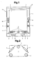
- FIG. 1 shows an elevator car 13 with a car body 1 in a support frame 12, which has side plates 4, a lower yoke 2 and an upper yoke 3.
- the cabin body 1 rests on three oil slide cushion units 5 and is actuated by actuating cylinders 6, which on the one hand are rotatably attached to the lower yoke 2 and on the other hand engage at three points on the underside of the cabin body 1, in different horizontal directions Positions brought.
- actuating cylinders 6 which on the one hand are rotatably attached to the lower yoke 2 and on the other hand engage at three points on the underside of the cabin body 1, in different horizontal directions Positions brought.
- Position transmitter 9 are shown between the car body 1 and side plates 4.
- a mechanical fixing unit 10 is also located laterally between the cabin body 1 and the side plate 4.
- a hydraulic unit 7 with a control block 7.1 and an electrical control unit 8 are accommodated.
- the geometrical arrangement of the oil slide cushion units 5 and the actuating cylinder 6 can be seen from FIG.
- the oil slide cushion units 5 are arranged in a triangular shape with three pieces, the lower side with two oil slide cushion units 5 being the entrance side of the cabin.
- the three actuating cylinders 6 are arranged in a triangle for the purpose of mastering all positioning directions.
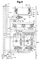
- FIG. 3 shows the interaction of the functional units 1 to 10 shown in FIG. 1 plus an elevator control, designated 11, which supplies the primary control signals.
- a motor 7.3 drives a hydraulic pump 7.2 with a constant displacement and a current direction.
- An outgoing pressure line 7.5 feeds the functional units oil slide cushion units 5, actuating cylinders 6 and mechanical fixing units 10.
- the control block 7.1 shown in FIG. 1 is broken down here into the control valves and orifices functionally assigned to the individual functional units.
- 6.9 is a 4/3-way valve
- 6.5 is a 2/2-way valve
- 10.6 is a 4/2-way valve
- 6.8 is an electrically controlled orifice
- 10.9 is a fixed orifice.
- the two 4/3-way valves 6.9 each have an actuating magnet 6.10 and an actuating magnet 6.11.
- the valve positions shown show the stable return springs, not shown generated rest position in the de-energized state.
- the two 2/2-way valves 6.5 each have a return spring 6.7 and an actuating magnet 6.6
- the 4/2-way valve 10.6 has a return spring 10.8 and an actuating magnet 10.7.
- the actuating magnets 6.10, 6.11, 6.6 and 10.7 and the electrically controlled orifices 6.8 are each connected to an electrical control line 7.8.
- 7.7 is an electrical feed line for the motor 7.3.
- a return line 7.6 leads drain and / or return oil from the functional groups back into a tank 7.4.
- the actuating cylinders 6 are designed as double-acting hydraulic cylinders and consist of a cylinder housing 6.1 provided with two connection openings, which is connected with a joint 6.4 to the lower yoke 2 and a piston 6.2 with a piston rod 6.3, which in turn is connected in an articulated manner to the cabin body 1 .
- the third actuating cylinder 6 is not shown in order to simplify the hydraulic diagram.
- the outlet sides of the 4/3-way valves 6.9 are connected to the two connection openings on the cylinder housings 6.1 by two oil lines 6.12 and 6.13.
- a cross-connection 6.14 between the two oil lines leads via an electrically controlled orifice 6.8 and a 2/2-way valve 6.5.
- a signal line 9.6 is connected to the position transmitters 9, which represent the respective horizontal position of the cabin body 1.
- the oil slide cushion unit 5 consists of a horizontal slide plate 5.1 provided with a vertical edge, a slide shoe 5.2 and a dust protection membrane 5.3.
- An oil cushion zone is designated with 5.6, an oil inlet opening with 5.4 and an oil outlet opening with 5.5.
- Slide shoes 5.2 are attached to the underside of the cabin body 1.
- the mechanical fixing units 10 each consist of a cylinder housing 10.10, which is attached to the side plate 4, a compression spring 10.1, a piston 10.2 and one its lower end, for example, a conical piston rod 10.3, which in turn dips into a suitable opening 10.5 of a tab 10.4 fastened to the cabin body 1.
- FIG. 5 shows a side view of one of the two position transmitters 9.
- a transmitter part 9.1 connected to the car body 1 sends a light beam 9.2 through a space 9.6 to a light sensor plate 9.3 which is attached to the side plate 4 of the support frame 12.
- FIG. 6 shows the light sensor plate 9.3 in one embodiment.
- the sensor surface is divided into five circular rings K1 to K5 and these in turn into the eight circular segments KS1 to KS8.
- a light spot LF generated by the light beam 9.2 has a diameter of, for example, twice the size of the spaces between the circular rings K1 to K8 or between the circular segments KS1 to KS8.
- Two marked position points are called PS for stop position and PF for travel position.
- the individual sensor segments are designated 9.7.
- FIGS. 7 and 8 show typical functional sequences, the course of which can be read directly from the functional blocks. The operations contained therein are explained in more detail below.
- the device for carrying out the method shown in the figures and described above works as follows:
- the device generally works according to the known principle of the friction-free horizontal movement of loads on oil, water, magnetic or air cushions.
- the cabin body 1 is supported on three oil slide cushion units 5, which are arranged in a triangular shape on a horizontal plane. Three support points are advantageously chosen in order to support all Oil slide cushion units 5 to obtain the same high oil cushion zones 5.6.
- the oil cushion is created when the hydraulic pump 7.2 pumps with constant displacement through the opening 5.4 pressure oil into the oil cushion zone 5.6 between the sliding plate 5.1 and the slide shoe 5.2.
- Volume regulators (not shown) in the feed lines to the inlet openings 5.4 ensure that the oil cushions in all three oil slide cushion units 5 take place simultaneously and uniformly.
- the clear widths of the return flow system are dimensioned so that there is no jam in the sliding plates 5.1. If the hydraulic pump 7.2 is stopped by switching off the motor 7.3, the cabin body 1 sinks immediately and stands firmly with the slide shoes 5.2 on the sliding plates 5.1.
- the hydraulic pump 7.2 is advantageously designed as a multi-piston or gear pump that does not run too fast.
- the functional units 5, 6, 7, 9 and 10 shown in FIG. 4 are controlled by the electrical control unit 8, which in turn receives and processes signals from the elevator control 11 and the position transmitters 9.
- the essential elements of the electrical control unit 8 are a computer system with corresponding control and regulator programs and an interface group for signal and data input / output as well as amplifier stages for controlling the solenoid coils of the valves and contactors.
- the elevator control 11 supplies the signals travel command, deceleration command and actual speed value.
- the electrical control unit 8 supplies status signals of the device to the elevator control 11.
- These status signals contain the information car body 1 mechanically fixed / not fixed, oil cushion / no oil cushion and that of the exact current position of the car body 1. The latter is dependent on the two one side of the cabin body 1 attached position signaling 9 signals.
- the horizontal position of each side of the cabin body 1 is transmitted to the light sensor plate 9.3 with a light beam 9.2.
- the projected light spot LF illuminates partial areas of one or more or a maximum of four sensor segments 9.7.
- the partially illuminated sensor segments 9.7 give corresponding active electrical signals to the electrical control unit 8.
- the address of a segment 9.7 can be, for example, K3 / KS3 and thus announces that that sensor segment 9.7 of the circular ring K3 is meant in the circular segment KS3.
- the sensor segments 9.7 are arranged in matrix form.
- the PF position is in the center and further out, for example between K3 and K4 or between KS4 and KS5 the Stop PS position. These two position points are local setpoints and correspond to the two operating states of the elevator: travel and standstill.
- the driving position PF is assumed while driving, whereby the cabin body 1 is spaced a few centimeters from the door-side shaft fittings and thus has the necessary scope to absorb the horizontal bumps.
- the active displacement of the car body 1 into certain horizontal positions takes place by means of the diagonally arranged actuating cylinders 6.
- the first operating mode is called forced positioning.
- the control valves 6.5 in the cross-connections 6.14 remain in the closed position shown in FIG. 4 and the movements of the pistons 6.2 inevitably take place in accordance with the respective position of the control valve 6.9 and the volume flow size in the individual feed lines.
- a horizontal displacement of the car body 1 is only carried out when it is floating or the oil pads are present in the oil slide pad units 5.
- the second operating mode is called slip positioning.
- the control valves 6.5 are opened, and depending on the position of the electrically controlled orifices 6.8, when the actuating cylinders 6 are actuated, a corresponding parallel current is produced in the cross-connections 6.14, which reduces the actuating force of the actuating cylinders to the required extent.
- the slip positioning has the task of keeping the floating car body 1 in position PF while driving against horizontal drift forces with minimal actuating force. Horizontal impacts are conducted by the quasi free-running pistons into the open parallel oil flow circuits of the cross-connections 6.14 and are no longer noticeable within the cabin body because only a relative movement of the support frame 12 to the cabin body 1 takes place.
- the pistons 6.2 have non-contact baffle seals and the piston rod bushings on the cylinder housings 6.1 are also provided with non-contact baffle seals and a linear roller bearing. If a permanent displacement of the horizontal position is signaled after horizontal impacts, the position is corrected to the position points PF with a slightly increased actuating force. The The size of the actuating force depends on the respective opening widths of the electrically controlled orifices 6.8. Regardless of the operating mode, the direction of adjustment results from the position of the control valves 6.9.
- the required manipulated variable, actuating force, actuating direction and actuating speed must be calculated from the combined signals from the position transmitter 9 in the electrical control unit 8.
- the actuating force magnitude and the actuating speed have, for example, a progressive characteristic which is dependent on the radial deviation from the point PF. This is to prevent the vertical edge of the sliding plate 5.1 from being touched by the sliding foot 5.2 once each time the frame 12 repeats the same in the same direction.
- the actuating force when entering a floor is increased in a quadratic manner depending on the driving speed in order to control the position point PS in this phase and to gradually switch to the inevitable operating mode.
- the inevitable operating mode is used for the concrete positioning and the stable holding of the still floating car body 1 in position PS when entering a floor or immediately before the mechanical fixing of the car body 1 in the support frame 12.
- the latter is done by the mechanical fixing units 10 and takes place before the mechanical Coupling the cabin with the landing door instead.
- the control valve 10.6 is brought into that position shown in FIG. 4 by switching off the actuating magnet 10.7.
- the compression spring 10.1 can now push the piston 10.3 down and the displaced oil flows through the orifice 10.9 and the return line 7.6 into the tank 7.6.
- the conical ends of the piston rods 10.3 dip into the openings 10.5 of the tabs 10.4 on the cabin body 1 and hold it immovably in the position determined thereby.
- FIGS. 7 and 8 The chronological sequence of the individual functions described above during normal elevator travel is shown in FIGS. 7 and 8.
- the method and the device available for exercising it begin to work at the moment when there is an active travel command from the elevator control 11 when the door is closed and locked (FIG. 7).
- Due to the running hydraulic pump 7.2 the cabin body 1 is lifted to the floating level by the oil cushion that is created, the pistons 10.3 of the mechanical fixing unit 10 are pushed up, which removes the mechanical fixation of the cabin body 1 in the support frame 12, and the actuating cylinder 6 inevitably positions the cabin body 1 to the position points PF.
- the actuating cylinders 6 When these position points PF are reached - the cabin has now started to move - the actuating cylinders 6 are switched to the slip positioning operating mode.
- the transition from the "forced positioning" mode to the "slip positioning” mode is smooth and begins before the position points PF are reached. While driving, the device works as already described.
- the next phase begins with the arrival of the deceleration command (FIG. 8), which results in a deceleration until the elevator comes to a standstill.
- the positioning force of the actuating cylinders 6 increases quadratically with the decrease in speed, which means a gradual transition from the slip positioning to the inevitable positioning. For example, 2 meters in front of the target floor the displacement of the car body 1 to the position points PS made. This shift must be completed, for example, 1 meter in front of the target floor, because now, before the doors are coupled, the car body 1 must be firmly placed on the base and mechanically fixed, which is done by stopping the hydraulic pump 7.2.
- the positions PS are now maintained until the next trip.
- the position PS must be taken as late as possible in order to get the car body 1 as close as possible to the shaft wall and thus to reduce the air gap.
- the supply lines from the pressure line 7.5 to the individual functional units contain, in a further developed form, pressure and quantity-regulating elements and / or check valves, which have not yet been shown, in order to optimize the controlled functions.
- separate hydraulic pumps 7.2 are provided with adapted characteristics for the individual functional units. It is also possible to carry out the method with a pneumatic device or to use different media, oil and air with the devices required for the individual functional units. Likewise, a method and a device with magnetic cushions from mutually repelling electro and / or permanent magnets is possible according to the principle of magnetic levitation trains. It offers for the horizontal displacement of the cabin body 1 of the linear motor.
- the electrical control of the hydraulic device according to FIG. 4 can also be carried out by means of an electrical-hydraulic-fluidic analogy.
Landscapes
- Engineering & Computer Science (AREA)
- Mechanical Engineering (AREA)
- Structural Engineering (AREA)
- Automation & Control Theory (AREA)
- Civil Engineering (AREA)
- Computer Networks & Wireless Communication (AREA)
- Cage And Drive Apparatuses For Elevators (AREA)
- Vibration Prevention Devices (AREA)
- Body Structure For Vehicles (AREA)
Priority Applications (1)
| Application Number | Priority Date | Filing Date | Title |
|---|---|---|---|
| AT89114779T ATE88679T1 (de) | 1988-11-02 | 1989-08-10 | Verfahren und vorrichtung zur ausuebung des verfahrens fuer die schwingungsabsorbierung an kabinen bei schnellaufenden aufzuegen. |
Applications Claiming Priority (2)
| Application Number | Priority Date | Filing Date | Title |
|---|---|---|---|
| CH4073/88 | 1988-11-02 | ||
| CH407388 | 1988-11-02 |
Publications (2)
| Publication Number | Publication Date |
|---|---|
| EP0366883A1 true EP0366883A1 (fr) | 1990-05-09 |
| EP0366883B1 EP0366883B1 (fr) | 1993-04-28 |
Family
ID=4269311
Family Applications (1)
| Application Number | Title | Priority Date | Filing Date |
|---|---|---|---|
| EP89114779A Expired - Lifetime EP0366883B1 (fr) | 1988-11-02 | 1989-08-10 | Procédé et dispositif pour absorber les vibrations de cabines d'ascenseurs à grande vitesse |
Country Status (6)
| Country | Link |
|---|---|
| US (1) | US5020639A (fr) |
| EP (1) | EP0366883B1 (fr) |
| JP (1) | JPH02175584A (fr) |
| AT (1) | ATE88679T1 (fr) |
| DE (1) | DE58904201D1 (fr) |
| ES (1) | ES2041910T3 (fr) |
Cited By (3)
| Publication number | Priority date | Publication date | Assignee | Title |
|---|---|---|---|---|
| EP0593296A3 (en) * | 1992-10-15 | 1994-06-08 | Toshiba Kk | Elevator passenger car |
| CN112173925A (zh) * | 2020-09-25 | 2021-01-05 | 上海申菱电梯配件有限公司 | 一种电梯轿底结构 |
| CN112173926A (zh) * | 2020-09-25 | 2021-01-05 | 上海申菱电梯配件有限公司 | 电梯轿底结构 |
Families Citing this family (26)
| Publication number | Priority date | Publication date | Assignee | Title |
|---|---|---|---|---|
| US5294757A (en) * | 1990-07-18 | 1994-03-15 | Otis Elevator Company | Active vibration control system for an elevator, which reduces horizontal and rotational forces acting on the car |
| US5322144A (en) * | 1990-07-18 | 1994-06-21 | Otis Elevator Company | Active control of elevator platform |
| US5321217A (en) * | 1990-07-18 | 1994-06-14 | Otis Elevator Company | Apparatus and method for controlling an elevator horizontal suspension |
| US5308938A (en) * | 1990-07-18 | 1994-05-03 | Otis Elevator Company | Elevator active suspension system |
| US5400872A (en) * | 1990-07-18 | 1995-03-28 | Otis Elevator Company | Counteracting horizontal accelerations on an elevator car |
| JP2756208B2 (ja) * | 1991-03-13 | 1998-05-25 | オーチス エレベータ カンパニー | 垂直走行中のエレベータかごの水平偏差修正装置 |
| JP2756207B2 (ja) * | 1991-03-13 | 1998-05-25 | オーチス エレベータ カンパニー | 垂直昇降路レール上のエレベータかごの水平偏差を測定する方法及び装置 |
| CA2072240C (fr) * | 1991-07-16 | 1998-05-05 | Clement A. Skalski | Elements horizontaux de suspension et commandes d'ascenseur |
| ZA927572B (en) * | 1991-10-24 | 1993-04-16 | Otis Elevator Co | Elevator ride quality. |
| GB2285251B (en) * | 1993-12-28 | 1997-12-10 | Hitachi Ltd | Elevator |
| JPH09208161A (ja) * | 1996-02-02 | 1997-08-12 | Toshiba Corp | エレベータのかご |
| US5955709A (en) * | 1996-07-31 | 1999-09-21 | Otis Elevator Company | Elevator control system featuring all-electromagnet vibration and centering elevator car controller for coupling a roller arranged on a pivot arm to a guide rail |
| US5866861A (en) * | 1996-08-27 | 1999-02-02 | Otis Elevator Company | Elevator active guidance system having a model-based multi-input multi-output controller |
| JP4131764B2 (ja) * | 1998-09-01 | 2008-08-13 | 東芝エレベータ株式会社 | エレベータ装置 |
| FR2789669B1 (fr) * | 1999-02-16 | 2001-05-04 | Sodimas | Dispositif de limitation de la charge embarquee dans une cabine d'ascenseur |
| US6435314B1 (en) * | 2000-03-24 | 2002-08-20 | Otis Elevator Company | Elevator platform stabilization coupler |
| US6357554B1 (en) * | 2000-07-11 | 2002-03-19 | Otis Elevator Company | Elevator ride improvements utilizing smart floor |
| US6668980B2 (en) | 2001-07-06 | 2003-12-30 | Thyssen Elevator Capital Corp. | Elevator car isolation system and method |
| AU2003218090A1 (en) * | 2003-03-12 | 2004-10-11 | Otis Elevator Company | Active elevator car balance system |
| US7503433B2 (en) * | 2003-04-07 | 2009-03-17 | Chiu Nan Wang | Elevator |
| JPWO2005100226A1 (ja) * | 2004-04-08 | 2007-08-30 | 三菱電機株式会社 | エレベータ装置 |
| WO2009143450A2 (fr) | 2008-05-23 | 2009-11-26 | Thyssenkrupp Elevator Capital Corporation | Système de guidage et d’équilibrage actif pour ascenseur |
| DE102014017357A1 (de) * | 2014-11-25 | 2016-05-25 | Thyssenkrupp Ag | Aufzuganlage |
| EP3369686B1 (fr) * | 2017-03-02 | 2020-08-26 | KONE Corporation | Ascenseur comprenant un moteur électrique linéaire |
| EP3517474A1 (fr) * | 2018-01-30 | 2019-07-31 | KONE Corporation | Procédé et unité de commande d'ascenseur pour commander un écart de seuil de porte d'un ascenseur et un ascenseur |
| IT202100004625A1 (it) * | 2021-02-26 | 2022-08-26 | Ironbox S R L | “sistema di trasporto” |
Citations (5)
| Publication number | Priority date | Publication date | Assignee | Title |
|---|---|---|---|---|
| US1669184A (en) * | 1926-10-21 | 1928-05-08 | Milo A Baker | Elevator |
| US2793264A (en) * | 1954-03-29 | 1957-05-21 | Chicago Elevator And Machine C | Elevator signal control |
| GB1407158A (en) * | 1972-12-01 | 1975-09-24 | Hitachi Ltd | Elevator device |
| GB2181275A (en) * | 1985-09-27 | 1987-04-15 | Elevator Gmbh | Compensating for lateral oscillation of lift car |
| US4660682A (en) * | 1982-11-10 | 1987-04-28 | Elevators Pty. Limited | Lift car support |
Family Cites Families (3)
| Publication number | Priority date | Publication date | Assignee | Title |
|---|---|---|---|---|
| US2726735A (en) * | 1955-02-23 | 1955-12-13 | New York Air Brake Co | Electric control for hydraulic lifts |
| JPS61215826A (ja) * | 1985-03-19 | 1986-09-25 | Sanai Kogyo Kk | 防振テ−ブル水平保持装置 |
| JPS6298684U (fr) * | 1985-12-11 | 1987-06-23 |
-
1989
- 1989-08-10 DE DE8989114779T patent/DE58904201D1/de not_active Expired - Fee Related
- 1989-08-10 ES ES198989114779T patent/ES2041910T3/es not_active Expired - Lifetime
- 1989-08-10 EP EP89114779A patent/EP0366883B1/fr not_active Expired - Lifetime
- 1989-08-10 AT AT89114779T patent/ATE88679T1/de active
- 1989-10-25 US US07/426,552 patent/US5020639A/en not_active Expired - Fee Related
- 1989-11-02 JP JP1287279A patent/JPH02175584A/ja active Pending
Patent Citations (5)
| Publication number | Priority date | Publication date | Assignee | Title |
|---|---|---|---|---|
| US1669184A (en) * | 1926-10-21 | 1928-05-08 | Milo A Baker | Elevator |
| US2793264A (en) * | 1954-03-29 | 1957-05-21 | Chicago Elevator And Machine C | Elevator signal control |
| GB1407158A (en) * | 1972-12-01 | 1975-09-24 | Hitachi Ltd | Elevator device |
| US4660682A (en) * | 1982-11-10 | 1987-04-28 | Elevators Pty. Limited | Lift car support |
| GB2181275A (en) * | 1985-09-27 | 1987-04-15 | Elevator Gmbh | Compensating for lateral oscillation of lift car |
Cited By (5)
| Publication number | Priority date | Publication date | Assignee | Title |
|---|---|---|---|---|
| EP0593296A3 (en) * | 1992-10-15 | 1994-06-08 | Toshiba Kk | Elevator passenger car |
| CN112173925A (zh) * | 2020-09-25 | 2021-01-05 | 上海申菱电梯配件有限公司 | 一种电梯轿底结构 |
| CN112173926A (zh) * | 2020-09-25 | 2021-01-05 | 上海申菱电梯配件有限公司 | 电梯轿底结构 |
| CN112173926B (zh) * | 2020-09-25 | 2021-12-31 | 上海申菱电梯配件有限公司 | 电梯轿底结构 |
| CN112173925B (zh) * | 2020-09-25 | 2021-12-31 | 上海申菱电梯配件有限公司 | 一种电梯轿底结构 |
Also Published As
| Publication number | Publication date |
|---|---|
| ES2041910T3 (es) | 1993-12-01 |
| EP0366883B1 (fr) | 1993-04-28 |
| DE58904201D1 (de) | 1993-06-03 |
| US5020639A (en) | 1991-06-04 |
| JPH02175584A (ja) | 1990-07-06 |
| ATE88679T1 (de) | 1993-05-15 |
Similar Documents
| Publication | Publication Date | Title |
|---|---|---|
| EP0366883B1 (fr) | Procédé et dispositif pour absorber les vibrations de cabines d'ascenseurs à grande vitesse | |
| DE10150382B4 (de) | Fahrsimulator | |
| EP0350582B1 (fr) | Appareil pour l'amortissement de vibrations des cubines d'élévateurs | |
| EP2219985B1 (fr) | Système d'ascenseur avec cabines d'ascenseur mobiles dans les sens vertical et horizontal | |
| DE69813332T2 (de) | Schienenbremse | |
| DE112005000607B4 (de) | Bremsvorrichtung für einen Aufzug | |
| EP2760777A1 (fr) | Système de freinage à actionnement électromécanique | |
| EP3381761A1 (fr) | Actionneur de commande d'un ensemble de roue d'un véhicule ferroviaire | |
| DE68918811T2 (de) | Stützapparat für Fahrzeuglinearmotor. | |
| EP1006071A1 (fr) | Ascenseur avec deux moteurs | |
| WO2018234211A1 (fr) | Ensemble cabine | |
| EP2512969A1 (fr) | Système d'ascenseur à deux cabines superposées | |
| DD151280A5 (de) | Einrichtung zur selbsttaetigen regelung der bremskraft einer durch verschiebbare oder verdrehbare dauermagnete stufenlos schaltbaren wirbelstrom-und/oder friktions-schienenbremse | |
| WO2021110726A1 (fr) | Appareil de guidage et de freinage d'un corps mobile d'un système de levage, ledit corps devant être déplacé le long d'une voie de guidage | |
| DE2350504A1 (de) | Stapelkran | |
| EP1479636A1 (fr) | Amortisseur qui peut créer une zone d' inspection sûre pour ascenseur | |
| WO2012084381A1 (fr) | Installation d'ascenseur à double pont | |
| CH600426A5 (en) | Electrohydraulic transverse inclination mechanism | |
| EP4081474A1 (fr) | Système de levage à entraînement par friction | |
| DE2344570A1 (de) | Schwingungsisolierungsanordnung | |
| DE2502313A1 (de) | Magnetschwebebahn | |
| DE2440645A1 (de) | Bremsvorrichtung fuer schienenfahrzeuge | |
| AT211510B (de) | Betätigungsgerät für das genaue Anhalten von Aufzügen | |
| DE3604163A1 (de) | Einrichtung zum steuern einer hydraulischen kolbengleisbremse | |
| DE2145747C3 (de) | Hydraulische Einrichtung für die Gleisbogensteuerung bei Schienenfahrzeugen |
Legal Events
| Date | Code | Title | Description |
|---|---|---|---|
| PUAI | Public reference made under article 153(3) epc to a published international application that has entered the european phase |
Free format text: ORIGINAL CODE: 0009012 |
|
| AK | Designated contracting states |
Kind code of ref document: A1 Designated state(s): AT CH DE ES FR GB IT LI |
|
| 17P | Request for examination filed |
Effective date: 19900927 |
|
| 17Q | First examination report despatched |
Effective date: 19911127 |
|
| GRAA | (expected) grant |
Free format text: ORIGINAL CODE: 0009210 |
|
| AK | Designated contracting states |
Kind code of ref document: B1 Designated state(s): AT CH DE ES FR GB IT LI |
|
| REF | Corresponds to: |
Ref document number: 88679 Country of ref document: AT Date of ref document: 19930515 Kind code of ref document: T |
|
| REF | Corresponds to: |
Ref document number: 58904201 Country of ref document: DE Date of ref document: 19930603 |
|
| ET | Fr: translation filed | ||
| GBT | Gb: translation of ep patent filed (gb section 77(6)(a)/1977) |
Effective date: 19930609 |
|
| ITF | It: translation for a ep patent filed | ||
| REG | Reference to a national code |
Ref country code: ES Ref legal event code: FG2A Ref document number: 2041910 Country of ref document: ES Kind code of ref document: T3 |
|
| PLBE | No opposition filed within time limit |
Free format text: ORIGINAL CODE: 0009261 |
|
| 26N | No opposition filed | ||
| PGFP | Annual fee paid to national office [announced via postgrant information from national office to epo] |
Ref country code: GB Payment date: 19950717 Year of fee payment: 7 |
|
| PGFP | Annual fee paid to national office [announced via postgrant information from national office to epo] |
Ref country code: ES Payment date: 19950720 Year of fee payment: 7 |
|
| PGFP | Annual fee paid to national office [announced via postgrant information from national office to epo] |
Ref country code: DE Payment date: 19950726 Year of fee payment: 7 |
|
| PGFP | Annual fee paid to national office [announced via postgrant information from national office to epo] |
Ref country code: FR Payment date: 19950727 Year of fee payment: 7 Ref country code: AT Payment date: 19950727 Year of fee payment: 7 |
|
| PGFP | Annual fee paid to national office [announced via postgrant information from national office to epo] |
Ref country code: CH Payment date: 19951120 Year of fee payment: 7 |
|
| PG25 | Lapsed in a contracting state [announced via postgrant information from national office to epo] |
Ref country code: GB Effective date: 19960810 Ref country code: AT Effective date: 19960810 |
|
| PG25 | Lapsed in a contracting state [announced via postgrant information from national office to epo] |
Ref country code: ES Free format text: LAPSE BECAUSE OF EXPIRATION OF PROTECTION Effective date: 19960812 |
|
| PG25 | Lapsed in a contracting state [announced via postgrant information from national office to epo] |
Ref country code: LI Effective date: 19960831 Ref country code: CH Effective date: 19960831 |
|
| GBPC | Gb: european patent ceased through non-payment of renewal fee |
Effective date: 19960810 |
|
| REG | Reference to a national code |
Ref country code: CH Ref legal event code: PL |
|
| PG25 | Lapsed in a contracting state [announced via postgrant information from national office to epo] |
Ref country code: FR Effective date: 19970430 |
|
| PG25 | Lapsed in a contracting state [announced via postgrant information from national office to epo] |
Ref country code: DE Effective date: 19970501 |
|
| REG | Reference to a national code |
Ref country code: FR Ref legal event code: ST |
|
| REG | Reference to a national code |
Ref country code: ES Ref legal event code: FD2A Effective date: 19990601 |
|
| PG25 | Lapsed in a contracting state [announced via postgrant information from national office to epo] |
Ref country code: IT Free format text: LAPSE BECAUSE OF NON-PAYMENT OF DUE FEES;WARNING: LAPSES OF ITALIAN PATENTS WITH EFFECTIVE DATE BEFORE 2007 MAY HAVE OCCURRED AT ANY TIME BEFORE 2007. THE CORRECT EFFECTIVE DATE MAY BE DIFFERENT FROM THE ONE RECORDED. Effective date: 20050810 |