EP0367009A1 - Système de freinage - Google Patents
Système de freinage Download PDFInfo
- Publication number
- EP0367009A1 EP0367009A1 EP89119183A EP89119183A EP0367009A1 EP 0367009 A1 EP0367009 A1 EP 0367009A1 EP 89119183 A EP89119183 A EP 89119183A EP 89119183 A EP89119183 A EP 89119183A EP 0367009 A1 EP0367009 A1 EP 0367009A1
- Authority
- EP
- European Patent Office
- Prior art keywords
- impeller
- negative pressure
- air passage
- brake system
- air
- Prior art date
- Legal status (The legal status is an assumption and is not a legal conclusion. Google has not performed a legal analysis and makes no representation as to the accuracy of the status listed.)
- Withdrawn
Links
- 238000007599 discharging Methods 0.000 claims abstract description 3
- 230000005540 biological transmission Effects 0.000 claims description 10
- 238000001816 cooling Methods 0.000 abstract description 5
- 238000011144 upstream manufacturing Methods 0.000 abstract description 3
- 230000008878 coupling Effects 0.000 description 7
- 238000010168 coupling process Methods 0.000 description 7
- 238000005859 coupling reaction Methods 0.000 description 7
- 239000012530 fluid Substances 0.000 description 6
- 238000010586 diagram Methods 0.000 description 5
- 230000007423 decrease Effects 0.000 description 4
- 230000015556 catabolic process Effects 0.000 description 3
- 230000006835 compression Effects 0.000 description 1
- 238000007906 compression Methods 0.000 description 1
- 230000004048 modification Effects 0.000 description 1
- 238000012986 modification Methods 0.000 description 1
- XLYOFNOQVPJJNP-UHFFFAOYSA-N water Substances O XLYOFNOQVPJJNP-UHFFFAOYSA-N 0.000 description 1
Images

Classifications
-
- B—PERFORMING OPERATIONS; TRANSPORTING
- B60—VEHICLES IN GENERAL
- B60T—VEHICLE BRAKE CONTROL SYSTEMS OR PARTS THEREOF; BRAKE CONTROL SYSTEMS OR PARTS THEREOF, IN GENERAL; ARRANGEMENT OF BRAKING ELEMENTS ON VEHICLES IN GENERAL; PORTABLE DEVICES FOR PREVENTING UNWANTED MOVEMENT OF VEHICLES; VEHICLE MODIFICATIONS TO FACILITATE COOLING OF BRAKES
- B60T1/00—Arrangements of braking elements, i.e. of those parts where braking effect occurs specially for vehicles
- B60T1/02—Arrangements of braking elements, i.e. of those parts where braking effect occurs specially for vehicles acting by retarding wheels
- B60T1/08—Arrangements of braking elements, i.e. of those parts where braking effect occurs specially for vehicles acting by retarding wheels using fluid or powdered medium
-
- B—PERFORMING OPERATIONS; TRANSPORTING
- B60—VEHICLES IN GENERAL
- B60T—VEHICLE BRAKE CONTROL SYSTEMS OR PARTS THEREOF; BRAKE CONTROL SYSTEMS OR PARTS THEREOF, IN GENERAL; ARRANGEMENT OF BRAKING ELEMENTS ON VEHICLES IN GENERAL; PORTABLE DEVICES FOR PREVENTING UNWANTED MOVEMENT OF VEHICLES; VEHICLE MODIFICATIONS TO FACILITATE COOLING OF BRAKES
- B60T1/00—Arrangements of braking elements, i.e. of those parts where braking effect occurs specially for vehicles
- B60T1/02—Arrangements of braking elements, i.e. of those parts where braking effect occurs specially for vehicles acting by retarding wheels
- B60T1/06—Arrangements of braking elements, i.e. of those parts where braking effect occurs specially for vehicles acting by retarding wheels acting otherwise than on tread, e.g. employing rim, drum, disc, or transmission or on double wheels
- B60T1/062—Arrangements of braking elements, i.e. of those parts where braking effect occurs specially for vehicles acting by retarding wheels acting otherwise than on tread, e.g. employing rim, drum, disc, or transmission or on double wheels acting on transmission parts
-
- F—MECHANICAL ENGINEERING; LIGHTING; HEATING; WEAPONS; BLASTING
- F16—ENGINEERING ELEMENTS AND UNITS; GENERAL MEASURES FOR PRODUCING AND MAINTAINING EFFECTIVE FUNCTIONING OF MACHINES OR INSTALLATIONS; THERMAL INSULATION IN GENERAL
- F16D—COUPLINGS FOR TRANSMITTING ROTATION; CLUTCHES; BRAKES
- F16D57/00—Liquid-resistance brakes; Brakes using the internal friction of fluids or fluid-like media, e.g. powders
Definitions
- the present invention relates to a brake system for a vehicle, and particularly to a brake system applying a brake force of various strength to an element of a power transmission line of the vehicle.
- a large amount of heat exchange takes place in braking a large vehicle such as a large bus or truck and usually such a vehicle is equipped with an auxiliary brake system in addition to a main brake system (foot brake).
- a large vehicle such as a large bus or truck and usually such a vehicle is equipped with an auxiliary brake system in addition to a main brake system (foot brake).
- foot brake main brake system
- the auxiliary brake system In one type of the auxiliary brake system, such as an exhaust brake, the auxiliary brake system produces a force which comes from the vehicle wheel side toward an engine of the vehicle. The crankshaft of the engine is rotated by such a force, thereby the engine is decelerated.
- a rotor is selectively connected with a crankshaft or a propeller shaft of the vehicle in a manner such that it consumes an energy of the engine when it is rotated by the engine.
- the consumed energy serves as a brake force to the engine.
- An electrical retarder and a fluid retarder are the typical brake systems employing the rotor.
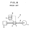
- Figure 8 of the accompaying drawings illustrates the fluid retarder a .
- the fluid retarder a serves as a part of a power transmission line d of a vehicle which connects an engine b with wheels c .
- an eddy of fluid such as water or oil, is generated between a rotor e fixed to an output side of the retarder a and a stator f fixed to an input side of the retarder a , thereby absorbing an energy from the engine and then converting the energy to heat.
- the fluid is cooled by a heat exchanger h provided in a tank g .
- the electrical retarder has electromagnets and a rotor which rotates between the electromagnets.
- An eddy current (Foucault current) is produced when the rotor rotates, and it is expelled in the form of ohmic heat.
- the above-mentioned retarders converts the torque of its outputs side to the heat energy, thereby applying a brake force to the engine. Therefore, a device for cooling a working medium (fluid or a rotor) is necessary in order to raise the braking efficiency.
- the cooling device raises the cost of the auxiliary brake system and makes the arrangement complicated.
- auxiliary brake system employs an impeller connected to a member of a power transmission line of the vehicle, for example a propeller shaft.
- the impeller is driven by an energy from the propeller shaft and sucks the external air. then the impeller consumes an energy of the engine, a brake force is applied to the engine.
- the brake force increases as the air introduced to the impeller increases. Therefore, if too much amount of air is introduced to the impeller, a too strong brake force is applied to the propeller shaft. This may result in a breakdown of the power transmission line of the vehicle, and a smooth deceleration is not expected.
- One object of the present invention is to provide a brake system which does not require a cooling device. Another object of the present invention is to provide a brake system whose brake force is easily adjustable. Still another object is to provide a brake system whose brake force is adjusted mechanically by itself in a manner such that an excessive brake force is not applied to the engine.
- a brake system which comprises an impeller connected to a member of a power transmission line of a vehicle, such as a propeller shaft, for applying a brake force to the propeller shaft, an impeller housing for rotatably housing the impeller and defining an air passage introducing/discharging an external air to/from the impeller, a throttle valve disposed in the air passage upstream of the impeller for adjusting the air flow rate in the air passage, and control means for actuating the throttle valve in accordance with the air flow rate in the air passage.
- the air passage includes an intake passage for introducing the air to the impeller and a discharge passage for expelling the air from the impeller.
- the throttle valve is located in the intake passage.
- the throttle valve is controlled by the valve control means, namely a negative pressure actuator.
- the negative pressure actuator includes a negative pressure chamber communicating with the discharge passage, a diaphragm defining the negative pressure chamber and driven by the negative pressure from the discharge passage, and a rod connected to the diaphragm at one end thereof and connected to the throttle valve at the other end thereof for moving the throttle valve with the diaphragm.
- the diaphragm of the negative pressure actuator is driven by the negative pressure in the negative pressure chamber derived from the discharge passage.
- the movement of the diaphragm is transmitted to the throttle valve via the rod, thereby throttling the intake passage.
- a brake force is applied to the engine.
- an amount of the air to be introduced to the 10 impeller is adjusted by the throttle valve and the control means.
- the control means adjusts the valve, i.e., the air flow rate in the intake passage, in accordance with the air flow rate in the discharge passage.
- the brake system of the present invention adjusts the brake force by itself mechanically.
- the brake system does not require a cooling device in order to raise the braking efficiency since it is not necessary to cool the working medium (the external air). Also, an excessively large brake force is not applied to the power transmission line of the vehicle. In addition, a stable deceleration is ensured. Furthermore, the brake system only needs a simple control arrangement.
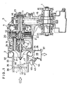
- numeral 1 designates an output shaft of an engine such as a propeller shaft.
- a brake system line 3 extends from the output shaft 1, and an impeller 3 is attached to the end of the brake system line 3. Therefore, an energy of the engine is transmitted from the output shaft 1 to the impeller 2.
- the brake system line 3 is housed in a casing 4.
- the brake system line 3 includes, as its major elements, a clutch shaft 11 extending parallel to the output shaft 1, a coupling 13 coaxially connected to the clutch shaft 11 via a clutch 12, an intermediate shaft 14 connected with the coupling 13, and an impeller shaft 15 extending parallel to and connected with the intermediate shaft 14.
- an output gear 16 is fixed on the output shaft 1 at the center of the output shaft 1, and the output gear 16 meshes with an idle gear 17 between the output shaft 1 and the clutch shaft 11.
- a speed increasing gear 18 is fixed on the clutch shaft 11 which meshes with the idle gear 17.
- the clutch 12 is provied at the output end of the clutch shaft 11.
- the clutch 12 includes a clutch wheel 19 and a clutch housing 20.
- a first set of clutch plates 21 are mounted on the clutch wheel 19 and a second set of clutch plates 22 are mounted on the clutch housing 20 in a manner such that these plates 21 and 22 are alternatively engaged with each other due to oil supplied from an oil source (not shown) through a bore 23 formed in the clutch shaft 11.
- an oil source not shown
- the clutch shaft 11 and the coupling 13 are connected with each other.
- a gear formed on the coupling 13 meshes with a gear formed on the intermediate shaft 14 at the output end of the coupling 13.
- An output gear 24 is fixed on the intermediate shaft 14, and meshes with a gear part formed on the impeller shaft 15.
- the impeller shaft 15 is coaxial with the coupling 13.
- An impeller housing 32 is attached to the main casing 4.
- An inlet 33 of the impeller, 33 is formed in the impeller housing 32 in the axial direction of the impeller 31 while an outlet for the impeller, 34, is formed in the impeller housing 32 in the radial direction of the impeller 31.
- An intake passage 36 extends upstream from the inlet 33 in the axial direction of the impeller 31.
- a discharge passage 37 extends downstream from the outlet 34 in the radial direction of the impeller 31.
- the impeller housing 32 has a passage wall 35 defining the intake and discharge passages 36 and 37.
- the impeller 31 is rotatably housed in the impeller housing 32.
- the inlet passage 36 introduces an atmosphere in the axial direction of the impeller 31 while the outlet passage 37 expells the air compressed by the impeller 31 in the radial direction of the impeller 31.
- An air passage 38 of the impeller 31 is defined by the inlet passage 36 and the outlet passage 37.
- a rotatable throttle valve 42 in the air passage 38.
- the throttle valve 41 is rotatably supported by a shaft 42 in the inlet passage 36 and provided with throttle control means 43 for changing the position thereof.
- the throttle control means 43 adjusts the inclination of the valve 41 so as to adjust the air flow rate in the inlet passage 36.
- the control means 43 includes a negative pressure actuator 44.
- the negative pressure actuator 44 includes, as shown in Figure 1, a pressure chamber 45 which is divided into two chambers by a diaphragm 46 transversely extending in the pressure chamber 45, as shown in Figure 2.
- a rod 47 is fixed on one face of the diaphragm 46 at one end thereof. Referring back to Figure 1, the rod 47 extends out of the pressure chamber 45 and is connected to an arm 48 via a hinge at the other end thereof.
- the arm 48 is fixed to the shaft 42 of the valve 41.
- the rod 47 and the arm 48 constitutes a linkage for rotating the valve 41 by 90 degrees at most with the shaft 42 being the rotation center.
- the chamber 49 opposite the chamber housing the rod 47 is a negative pressure chamber.
- a return spring 50 as shown in Figure 2.
- a tube 51 extends from the negative pressure chamber 49 to the discharge passage 37 for introducing a negative pressure of the discharge passage 37 to move the diaphragm 46.
- the tube 51 diagonally extends into the outlet passage 37, as illustrated in Figure 1.
- a negative pressure is applied into the chamber 49 of the diaphragm 46 as the impeller 31 compresses the air and expells it into the outlet passage 37. Then, the negative pressure moves the throttle valve 41 via the linkage 47 and 48. In other words, the valve 41 is mechanically adjusted in accordance with the negative pressure in the outlet passage 37.
- the clutch shaft 11 When the clutch shaft 11 is connected with the coupling 13 via the clutch 12, the power output from the output shaft 1 is transmitted to the impeller shaft 15, thereby driving the impeller 31.
- the clutch 12 is engaged by a hydraulic power when a vehicle driver wants to stop or decelerate the vehicle.
- the impeller 31 When the impeller 31 is driven, the air sucked into the inlet passage 36 is compressed by the impeller 31 and expelled through the outlet passage 37.
- the impeller 31 consumes an energy of the engine in order to compress the air, whereby an brake energy is applied to the output shaft 1, for example a propeller shaft, of the engine.
- FIG. 3 shows a relation between the rotational speed of the propeller shaft (revolutional speed of the engine) (horizonal axis) and the absorbed torque (brake force) (vertical axis).
- the dashed line A actual brake force
- the solid line B quired brake force
- one object of the present invention is to adjust the absorbed torque constant when the propeller shaft or the engine rotates at the high rotational speed, like the curve A in Figure 3.
- Figures 4 and 5 show characteristics of the brake system of the present invention respectively, in which the horizontal axes indicate the air flow rate and the vertical axes indicate a pressure ratio respectively.
- the pressure ratio is a ratio of an absolute pressure at the outlet to an absolute pressure at the inlet.
- the pressure ratio decreases as the air flow rate increases.
- the air flow rate decreases when the throttling by the valve 41 becomes large, namely in a high speed range between 60,000 rpm and 100,000 rpm, as indicated by the dashed line in Figure 5.
- the horizontal axis indicates the rotational speed of the propeller shaft (revolutional speed of the engine) and the vertical axes indicate the air flow rate as well as the venturi negative pressure.
- the solid line indicates the air flow rate and the single-dot line indicates the venturi negative pressure.
- the air flow rate increases with the rotational speed of the propeller shaft proportionally (solid line) whereas the venturi negative pressure increases with the rotational speed of the propeller shaft curvedly (dashed line).
- the difference between the air flow rate and the venturi negative pressure is slight, so that they have a similar tendency.
- the venturi negative pressure is considered proportional to the revolutional speed of the propeller shaft and its proportional constant is equal to that of the air flow rate.
- Figure 7 shows a diagram of which horizonal axis represents the venturi negative pressure instead of rotational speed of the propeller shaft.
- the vertical axis represents the air flow rate and the degree of throttling by the valve 41.
- the throttle valve 41 When the propeller shaft rotates at a low or a medium speed, the throttle valve 41 is not adjusted, i.e. , the valve 41 is at a full open position. Thus, the amount of the air introduced to the impeller 31 is not adjusted. Accordingly, a brake force corresponding to the amount of the air is applied to the propeller shaft 1.
- the throttle valve 41 is adjusted, i. e. , the valve throttles the inlet passage, in a manner such that the air flow rate be constant. Therefore, a brake force of constant strength is applied to the propeller shaft 1. Accordingly, the breakdown of the power transmission line of the vehicle never occurs and a stable deceleration is ensured by this brake system.
- the movement of the actuator 44 is controlled by employing a different return spring 50.
- the brake system controls the brake force by itself, so that the brake system does not need an external device for controlling the brake force which is usually a complicated device.
- the throttle valve 41 may be disposed in the outlet passage 37.
- the throttle valve is adjusted in accordance with the air flow rate in the inlet passage 36.
- the output shaft 1 may be a crankshaft.
Landscapes
- Engineering & Computer Science (AREA)
- Mechanical Engineering (AREA)
- General Engineering & Computer Science (AREA)
- Transportation (AREA)
- Control Of Throttle Valves Provided In The Intake System Or In The Exhaust System (AREA)
- Control Of Vehicle Engines Or Engines For Specific Uses (AREA)
Applications Claiming Priority (2)
| Application Number | Priority Date | Filing Date | Title |
|---|---|---|---|
| JP63273026A JPH02123249A (ja) | 1988-10-31 | 1988-10-31 | ターボリターダ |
| JP273026/88 | 1988-10-31 |
Publications (1)
| Publication Number | Publication Date |
|---|---|
| EP0367009A1 true EP0367009A1 (fr) | 1990-05-09 |
Family
ID=17522131
Family Applications (1)
| Application Number | Title | Priority Date | Filing Date |
|---|---|---|---|
| EP89119183A Withdrawn EP0367009A1 (fr) | 1988-10-31 | 1989-10-16 | Système de freinage |
Country Status (3)
| Country | Link |
|---|---|
| US (1) | US5007509A (fr) |
| EP (1) | EP0367009A1 (fr) |
| JP (1) | JPH02123249A (fr) |
Cited By (2)
| Publication number | Priority date | Publication date | Assignee | Title |
|---|---|---|---|---|
| DE10232404A1 (de) * | 2002-07-18 | 2004-01-29 | Adam Opel Ag | Strömungsbremse |
| CN108533643A (zh) * | 2018-05-29 | 2018-09-14 | 陕西法士特齿轮有限责任公司 | 一种串联液力缓速器 |
Families Citing this family (1)
| Publication number | Priority date | Publication date | Assignee | Title |
|---|---|---|---|---|
| US6315091B1 (en) | 1999-12-17 | 2001-11-13 | Daimlerchrysler Corporation | Brake cooling system |
Citations (8)
| Publication number | Priority date | Publication date | Assignee | Title |
|---|---|---|---|---|
| GB285910A (en) * | 1927-02-25 | 1928-04-19 | Bbc Brown Boveri & Cie | Improvements in and relating to blowers |
| GB746681A (en) * | 1954-01-15 | 1956-03-21 | Berliet Automobiles | A braking device for internal combustion engine vehicles |
| US3182759A (en) * | 1963-07-11 | 1965-05-11 | Goodyear Tire & Rubber | Combined turbo- and friction-brake with adjustable shrouding means and control meanstherefor |
| US3367461A (en) * | 1963-09-03 | 1968-02-06 | Eaton Yale & Towne | Retarder |
| US3805928A (en) * | 1972-08-18 | 1974-04-23 | Bennes Marrel | Regulation device for hydraulic turbo-retarders |
| DE1780730A1 (de) * | 1968-08-08 | 1977-06-23 | Daimler Benz Ag | Dauerbremseinrichtung fuer kraftfahrzeuge, insbesondere fuer nutzfahrzeuge und lastzuege |
| US4122668A (en) * | 1976-07-22 | 1978-10-31 | General Motors Corporation | Iris control for gas turbine engine air brake |
| EP0292010A1 (fr) * | 1987-05-22 | 1988-11-23 | Isuzu Motors Limited | Système de freinage pour moteur |
Family Cites Families (6)
| Publication number | Priority date | Publication date | Assignee | Title |
|---|---|---|---|---|
| US1416822A (en) * | 1921-01-24 | 1922-05-23 | John Ring | Pneumatic brake for vehicles |
| US1677481A (en) * | 1927-03-23 | 1928-07-17 | Bert A Lareva | Vehicle brake |
| US3155197A (en) * | 1962-10-24 | 1964-11-03 | Consolidation Coal Co | Multiple vehicle braking apparatus |
| US3265162A (en) * | 1963-10-11 | 1966-08-09 | Teves Kg Alfred | Vehicle-braking system |
| FR1465380A (fr) * | 1965-03-09 | 1967-01-13 | Applic Mach Motrices | Dispositif de freinage comportant un ralentisseur hydraulique |
| US4484668A (en) * | 1983-06-13 | 1984-11-27 | Master Pneumatic-Detroit, Inc. | Controller for vehicle retarder |
-
1988
- 1988-10-31 JP JP63273026A patent/JPH02123249A/ja active Pending
-
1989
- 1989-10-02 US US07/416,084 patent/US5007509A/en not_active Expired - Fee Related
- 1989-10-16 EP EP89119183A patent/EP0367009A1/fr not_active Withdrawn
Patent Citations (8)
| Publication number | Priority date | Publication date | Assignee | Title |
|---|---|---|---|---|
| GB285910A (en) * | 1927-02-25 | 1928-04-19 | Bbc Brown Boveri & Cie | Improvements in and relating to blowers |
| GB746681A (en) * | 1954-01-15 | 1956-03-21 | Berliet Automobiles | A braking device for internal combustion engine vehicles |
| US3182759A (en) * | 1963-07-11 | 1965-05-11 | Goodyear Tire & Rubber | Combined turbo- and friction-brake with adjustable shrouding means and control meanstherefor |
| US3367461A (en) * | 1963-09-03 | 1968-02-06 | Eaton Yale & Towne | Retarder |
| DE1780730A1 (de) * | 1968-08-08 | 1977-06-23 | Daimler Benz Ag | Dauerbremseinrichtung fuer kraftfahrzeuge, insbesondere fuer nutzfahrzeuge und lastzuege |
| US3805928A (en) * | 1972-08-18 | 1974-04-23 | Bennes Marrel | Regulation device for hydraulic turbo-retarders |
| US4122668A (en) * | 1976-07-22 | 1978-10-31 | General Motors Corporation | Iris control for gas turbine engine air brake |
| EP0292010A1 (fr) * | 1987-05-22 | 1988-11-23 | Isuzu Motors Limited | Système de freinage pour moteur |
Non-Patent Citations (1)
| Title |
|---|
| PATENT ABSTRACTS OF JAPAN vol. 13, no. 133 (M-809)(3481) 04 April 1989, & JP-A-63 302152 (ISUZU) 09 December 1988, * |
Cited By (3)
| Publication number | Priority date | Publication date | Assignee | Title |
|---|---|---|---|---|
| DE10232404A1 (de) * | 2002-07-18 | 2004-01-29 | Adam Opel Ag | Strömungsbremse |
| CN108533643A (zh) * | 2018-05-29 | 2018-09-14 | 陕西法士特齿轮有限责任公司 | 一种串联液力缓速器 |
| CN108533643B (zh) * | 2018-05-29 | 2024-04-09 | 陕西法士特齿轮有限责任公司 | 一种串联液力缓速器 |
Also Published As
| Publication number | Publication date |
|---|---|
| US5007509A (en) | 1991-04-16 |
| JPH02123249A (ja) | 1990-05-10 |
Similar Documents
| Publication | Publication Date | Title |
|---|---|---|
| US4882906A (en) | Engine braking system | |
| US5062498A (en) | Hydrostatic power transfer system with isolating accumulator | |
| US6167993B1 (en) | Braking system with a hydrodynamic retarder | |
| US3274768A (en) | Prime-mover system | |
| JP3981160B2 (ja) | 駆動ユニット及び駆動ユニットの動作方法 | |
| CN102292528B (zh) | 静液压的风扇驱动器 | |
| JPH03213455A (ja) | 流体静力学的ブレーキ負荷変換器 | |
| US5806402A (en) | Regulated speed linear actuator | |
| CA2556903C (fr) | Systeme de conversion et de dissipation d'energie | |
| JPH0617682B2 (ja) | 負荷応答流体動力制御装置 | |
| JP2007509274A (ja) | 駆動ユニットにおける利用度を最適化する方法および駆動ユニット | |
| EP0367009A1 (fr) | Système de freinage | |
| EP0219772A2 (fr) | Moteur à combustion interne turbocompressé | |
| US5279523A (en) | Cone disc transmission, particularly for motor vehicles | |
| US3905194A (en) | Hydrostatic transmission | |
| CA1044991A (fr) | Robinet regulateur pour reseau hydraulique | |
| CN106090179B (zh) | 控制方法以及以此方法运行的液力减速器 | |
| US8739529B2 (en) | Compressor system having limited suction charging pressure and method of operating same | |
| US4077212A (en) | Hydrostatic transmission control | |
| JPH0642365A (ja) | 駆動装置 | |
| JPS6361508B2 (fr) | ||
| JPS63302152A (ja) | タ−ビン式ブレ−キ | |
| JPS63302151A (ja) | タ−ビン式ブレ−キ | |
| JPS63302156A (ja) | タービン式ブレーキ | |
| JP2649500B2 (ja) | 湿式多板油圧クラッチの回転速度制御装置 |
Legal Events
| Date | Code | Title | Description |
|---|---|---|---|
| PUAI | Public reference made under article 153(3) epc to a published international application that has entered the european phase |
Free format text: ORIGINAL CODE: 0009012 |
|
| AK | Designated contracting states |
Kind code of ref document: A1 Designated state(s): AT BE CH DE ES FR GB GR IT LI LU NL SE |
|
| RBV | Designated contracting states (corrected) |
Designated state(s): DE GB |
|
| 17P | Request for examination filed |
Effective date: 19900919 |
|
| 17Q | First examination report despatched |
Effective date: 19911127 |
|
| STAA | Information on the status of an ep patent application or granted ep patent |
Free format text: STATUS: THE APPLICATION IS DEEMED TO BE WITHDRAWN |
|
| 18D | Application deemed to be withdrawn |
Effective date: 19921229 |