EP0367096B1 - Dispositif d'inclinaison de siège - Google Patents
Dispositif d'inclinaison de siège Download PDFInfo
- Publication number
- EP0367096B1 EP0367096B1 EP89119859A EP89119859A EP0367096B1 EP 0367096 B1 EP0367096 B1 EP 0367096B1 EP 89119859 A EP89119859 A EP 89119859A EP 89119859 A EP89119859 A EP 89119859A EP 0367096 B1 EP0367096 B1 EP 0367096B1
- Authority
- EP
- European Patent Office
- Prior art keywords
- gear
- reclining
- seat
- base frame
- motor
- Prior art date
- Legal status (The legal status is an assumption and is not a legal conclusion. Google has not performed a legal analysis and makes no representation as to the accuracy of the status listed.)
- Expired - Lifetime
Links
Images



Classifications
-
- B—PERFORMING OPERATIONS; TRANSPORTING
- B60—VEHICLES IN GENERAL
- B60N—SEATS SPECIALLY ADAPTED FOR VEHICLES; VEHICLE PASSENGER ACCOMMODATION NOT OTHERWISE PROVIDED FOR
- B60N2/00—Seats specially adapted for vehicles; Arrangement or mounting of seats in vehicles
- B60N2/02—Seats specially adapted for vehicles; Arrangement or mounting of seats in vehicles the seat or part thereof being movable, e.g. adjustable
- B60N2/22—Seats specially adapted for vehicles; Arrangement or mounting of seats in vehicles the seat or part thereof being movable, e.g. adjustable the back-rest being adjustable
- B60N2/2231—Worm and worm gear articulations
-
- B—PERFORMING OPERATIONS; TRANSPORTING
- B60—VEHICLES IN GENERAL
- B60N—SEATS SPECIALLY ADAPTED FOR VEHICLES; VEHICLE PASSENGER ACCOMMODATION NOT OTHERWISE PROVIDED FOR
- B60N2/00—Seats specially adapted for vehicles; Arrangement or mounting of seats in vehicles
- B60N2/02—Seats specially adapted for vehicles; Arrangement or mounting of seats in vehicles the seat or part thereof being movable, e.g. adjustable
- B60N2/22—Seats specially adapted for vehicles; Arrangement or mounting of seats in vehicles the seat or part thereof being movable, e.g. adjustable the back-rest being adjustable
- B60N2/2213—Gear wheel driven mechanism
-
- B—PERFORMING OPERATIONS; TRANSPORTING
- B60—VEHICLES IN GENERAL
- B60N—SEATS SPECIALLY ADAPTED FOR VEHICLES; VEHICLE PASSENGER ACCOMMODATION NOT OTHERWISE PROVIDED FOR
- B60N2/00—Seats specially adapted for vehicles; Arrangement or mounting of seats in vehicles
- B60N2/02—Seats specially adapted for vehicles; Arrangement or mounting of seats in vehicles the seat or part thereof being movable, e.g. adjustable
- B60N2/0224—Non-manual adjustments, e.g. with electrical operation
- B60N2/02246—Electric motors therefor
- B60N2/02253—Electric motors therefor characterised by the transmission between the electric motor and the seat or seat parts
Definitions
- the present invention relates generally to a seat reclining device for automotive vehicle seats and more specifically to a motor-driven seat reclining device provided with a Taumel mechanism (planetary gear type angle adjusting mechanism) as per the pre-characterizing part of claim 1, corresponding for example to FR-A-2 532 254.
- Taumel mechanism planetary gear type angle adjusting mechanism
- a large gear reduction ratio can be obtained by use of a Taumel mechanism or a planetary gear type angle adjusting mechanism.
- This mechanism is disclosed in U.S. patent US-A-3 401 979 by way of example, which is incorporated herein by reference.
- the prior-art seat reclining device usually comprises at least one base frame fixed on one side of a seat cushion; a reclining arm pivotally supported by the base frame via a Taumel mechanism with its reclining arm end fixed to one side of a seat back; a motor unit mounted on the base frame to drive the reclining arm via the Taumel mechanism; and a reclining gear fixed to one axle end of the Taumel mechanism and driven by the motor unit via a pinion attached to a reduction gear of the motor unit.
- the reclining arm, the reclining gear, the Taumel mechanism, etc. are arranged on the outside surface of the base frame together with the motor unit as disclosed in Japanese Published Unexamined (Kokai) Utility Model Appli. Nos. 56-103253, 60-48846 and 60-163058 or on the inside surface of the reclining arm together with the motor unit as disclosed in Japanese Published Unexamined (Kokai) Utility Model Appli. Nos. 58-185947 and 59-115948. Therefore, there is a problem in that the width of the seat provided with the reclining device is large and further it is rather difficult to full trim the vehicle seat for improvement in external appearance.
- a seat reclining device having a base frame (10U, 10L) fixed to a side surface of a seat cushion; a reclining arm (20) fixed to a side surface of a seat back and pivotally supported by the base frame via a Taumel mechanism (30); a reclining gear (50) for eccentrically rotating the reclining arm; and a motor unit (40) for driving the Taumel mechanism, wherein the motor unit includes a motor and a reduction gear with a motor output gear (44, 76) in mesh with the reclining gear, characterized in that the reclining gear and the motor output gear are disposed on an outside surface of the base frame and the motor and the reduction gear are disposed on an inside surface of the base frame.
- an output gear (32) of the Taumel mechanism is formed in the base frame (10U); an inner-gear (31) of the Taumel mechanism is formed in the reclining arm (20) in mesh with the outer gear; and the reclining arm (20) is disposed on the inside surface of the base frame (10U) and the reclining gear (50) is disposed on an opposite outside surface of the base frame (10U).
- the motor output gear (44, 76)disposed on the outside surface of the base frame (10L) is covered by a bracket (11) fixed to the base frame (10L).
- the reclining gear (50) disposed on the outside surface of the base frame (10U) is covered by a holder plate (36).
- the seat reclining device further comprises a reduction gear mechanism comprising: (a) a worm gear (70) in mesh with an output shaft (70a) of said motor unit (40); (b) a worm wheel (71) in mesh with said worm gear; (c) a small diameter gear (72) fixed coaxially with said worm wheel; (d) a large diameter gear (74) in mesh with said small diameter gear, said motor output gear (76) being fixed coaxially with said large diameter gear in mesh with said reclining gear (50), said worm gear, said worm wheel, said small diameter gear and said large diameter gear being arranged on an inside surface of said base frame and said motor output gear being arranged on an opposite outside surface of said base frame.
- a reduction gear mechanism comprising: (a) a worm gear (70) in mesh with an output shaft (70a) of said motor unit (40); (b) a worm wheel (71) in mesh with said worm gear; (c) a small diameter gear (72) fixed coaxially with said worm wheel; (d)
- a shock absorbing member (100) is disposed between the reclining gear (50) and an eccentric axle (33) of the Taumel mechanism (30) to absorb shock generated when the seat back is brought into contact with its frontmost position stopper.
- the seat reclining device according to the present invention since the various major parts are effectively arranged on both surfaces of the base frame to minimize the width of the device, it is possible to dispose the device elements within the seat cushion and the seat back. Therefore, the seat reclining device according to the present invention can be provided for even small-sized public cars.
- shock absorbing member is disposed near the reclining arm which generates shock, it is possible to effectively absorb shock generated when the seat back is reclined to its two frontmost and rearmost stoppers.
- a seat S is composed of a seat cushion Sc and a seat back Sb, and a seat reclining device 1 according to the present invention is arranged on both sides of and within the seat S.
- the seat reclining device 1A on the motor drive-side on the left side in Fig. 3 will be explained.
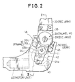
- the seat reclining device 1A comprises a pair of upper and lower base frames 10U and 10L both fixed to a cushion frame (not shown) fixed to the side of the seat cushion Sc; a reclining arm 20 fixed to the side of the seat back Sb and pivotally supported on the upper base frame 10U via a Taumel mechanism 30 (a planetary gear type pivotal angle adjusting mechanism); a motor unit 40 mainly including a motor 41 and a reduction gear 42 and mounted on the lower base frame 10L to drive the Taumel mechanism 30; and a reclining gear 50 fixed to an eccentric axle of the Taumel mechanism and rotated by the motor 41 of the motor unit 40.
- a Taumel mechanism 30 a planetary gear type pivotal angle adjusting mechanism
- a motor unit 40 mainly including a motor 41 and a reduction gear 42 and mounted on the lower base frame 10L to drive the Taumel mechanism 30
- a reclining gear 50 fixed to an eccentric axle of the Taumel mechanism and rotated by the motor 41 of the motor unit 40.
- the motor unit 40 comprises the motor 41, the reduction gear mechanism 42 coupled to a motor output shaft 43, a pinion gear 44 formed integral with an output shaft 44a of the reduction gear mechanism 42. Further, an idler gear 45 fixed to an idle gear axle 45a is interposed between the pinion gear 44 and the reclining gear 50.
- the motor 41 and the reduction gear mechanism 42 are mounted on the inside surface of the lower base frame 10L. Further, an outer end of the output shaft 44a of the reduction gear mechanism 42 is rotatably supported by a bracket 11 fixed to the lower base frame 10L with screws. The idler gear axle 45a of the idler gear 45 is also rotatably supported between the lower base frame 10L and the bracket 11.
- the Taumel mechanism 30 comprises an inner (circumferentially outside) gear 31, an outer (circumferentially inside) gear 32 and an eccentric axle 33.
- the inner gear 31 is formed in the reclining arm 20 by a high-accuracy emboss pressing machine.
- the outer gear 32 is also formed in the upper base frame 10U by a precise emboss pressing machine. Further, the number of teeth of the outer gear 32 is determined at least one tooth smaller than that of the inner gear 31.
- the inner gear 31 when the inner gear 31 is rotated eccentrically about the center of the outer gear 32, the mesh position between the two gears 31 and 32 rotates tooth by tooth in either direction, so that the reclining arm 20 formed with the inner gear 31 is pivoted very slowly about the outer gear 32.
- the eccentric axle 33 is formed with a first concentric axle portion 33a, a second concentric axle portion 33b, an outside tapered eccentric axle portion 33c, an inside tapered eccentric axle portion 33d, and a square end 33e.
- the large diameter concentric axle portion 33a is rotatably supported at the center of the outer gear 32 via a bearing 34.
- the small diameter concentric axle portion 33b is fixed to the center of the reclining gear 50.
- the outside tapered eccentric axle portion 33c is rotatably supported by a bearing 35 fixed to a holder plate 36.
- the inside tapered eccentric axle portion 33d is fixed to the center of the inner gear 31 of the reclining arm 20.
- the holder plate 36 fixed to the reclining arm 20 covers the upper base frame 10U, the reclining gear 50 and the eccentric axle 33.
- the two right and left side eccentric axles 33 are connected to each other via a connecting rod 35 by pressure fitting a square end 33e of the eccentric axle 33 into a hollow portion of the rod 35.
- the right side seat reclining device 1B is basically the same in structure as the left side seat reclining device 1A.
- the eccentric axle 33 is directly driven by the connecting rod 35 without providing the motor unit 40 (the motor 41 and the reduction gear 42), the pinion gear 44, the idler gear 45, the reclining gear 50, etc.
- the seat reclining device 1A and 1B constructed as described above is arranged within a full-trimmed seat S composed of the seat cushion Sc and the seat back Sb.
- the engagement position between the two gears 31 and 32 rotates tooth by tooth in either direction, so that the speed of the reclining arm 20 is reduced and the reclining arm 20 is pivoted about the eccentric axle 33 in the same rotative direction as the eccentric axle 33.
- the eccentric axle 33 rotates counterclockwise in Fig. 2
- the seat back is reclined forwardly, and when clockwise, the seat back is reclined backwardly, for instance.
- the feature of the first embodiment is to minimize the width of the seat reclining device 1A or 1B.
- the motor unit 40 (including the motor 41 and reduction gear mechanism 42) is disposed on the inside surface of the lower base frame 10L or in the seat cushion, and only the pinion gear 44 is disposed on the outside surface of the lower base frame 10L out of the seat cushion.
- the outer gear 32 is formed in the upper base frame 10U
- the reclining arm 20 formed with the inner gear 31 is disposed on the inside surface of the upper base frame 10U so as to be in mesh with the outer gear 32 and the reclining gear 50 is disposed on the outside surface of the upper base frame 10U.
- the pinion gear 44 and the idler gear 45 are covered by a bracket 11 from outside, and the reclining gear 50 is also covered by the holder plate 36 also from outside, it is possible to protect the seat cushion pad from being damaged by the reclining device, in particular from the moving gears 44, 45 and 50.
- Figs. 4 to 8 show a second embodiment of the seat reclining device according to the present invention, in which a worm gear and a worm wheel are provided in place of the reduction gear mechanism 42 of the first embodiment shown in Figs. 2 and 3.
- a worm gear 70 is fixed to a motor output shaft 43 of the motor 41.
- a worm wheel 71 fixed to a worm wheel axle 71a is in mesh with the worm gear 70.
- This worm wheel axle 71a is arranged perpendicular to the motor output shaft 43 and rotatably supported between a gear case 73 and a gear case cover 73a.
- a small diameter gear 72 fixed to the worm wheel axle 71a is in mesh with a large diameter gear 74.
- the large diameter gear 74 is fixed to a drive shaft 75 by fitting a boss portion 74a of the gear 74 to a serrated portion 75a of the drive shaft 75.
- this drive shaft 75 is rotatably supported between the gear case cover 73a and the lower base frame 10L via a bush 77, said drive shaft being rotatably supported by a bearing 73b attached to the gear case 73 and loosely supported by a hole 10U-1 of the upper base frame 10U, as shown in Fig. 6.
- the large diameter gear 74 is also housed between the gear case 73 and a gear case cover 73a.
- a drive gear 76 in mesh with the reclining gear 50 is formed integral with this drive shaft 75.
- a shock absorbing member or a damper member 100 is disposed between the eccentric axle 33 and the reclining gear 50 to reduce shock generated when the eccentric axle 33 is driven by the reclining gear 50.
- the eccentric axle 33 is formed with a first concentric axle portion 33a, a second concentric axle portion 33b, an outside cylindrical eccentric axle portion 33c, an inside cylindrical eccentric axle portion 33d, and a square end 33e.
- the above second concentric axle portion 33b is formed in roughly a square shape having two opposing flat surface portions 33f with a width b therebetween.
- the reclining gear 50 is formed at its center with a slot 50a having two opposing flat surface portions 50b with a width a (> b) therebetween.
- the damper member 100 made of an elastic material such as a rubber is formed with a disk portion 100a and two lug portions 100b projecting from the disk portion 100a perpendicular thereto and spaced with a space b therebetween. Further, a central hole 100c is formed at the center of the damper member 100.
- the reclining gear 50 is fitted to the second concentric axle portion 33b of the eccentric axle 33; the rubber damper member 100 is fitted to the eccentric axle 33 by inserting the two lug portions 100b into spaces formed between the second concentric axle portion 33b of the eccentric axle 33 and the central slot 50a of the reclining gear 50.
- the outside width a1 between the two lug portions 100b is determined a little wider than that a of the slot 50a of the reclining gear 50.
- the motor unit 40 i.e. motor 41
- a reduction gear mechanism including the worm gear 70, the worm wheel 71, the small diameter gear 72 and the large diameter gear 74
- the motor unit 40 and a reduction gear mechanism are disposed on the inside surface of the upper base frame 10U (as shown in Fig. 6) or within the seat cushion, and only the drive gear 76 is disposed on the outside surface of the upper base frame 10U out of the seat cushion.
- the outer gear 32 is also formed in the upper base frame 10U
- the reclining arm 20 formed with the inner gear 31 is disposed on the inside surface of the upper base frame 10U so as to be in mesh with the outer gear 32
- the reclining gear 50 is disposed on the outside surface of the upper base frame 10U, in the same way as in the first embodiment shown in Figs. 2 and 3.
- the motor unit 40 does not include a reduction gear mechanism and instead the reduction gear mechanism including the worm gear 70, the worm wheel 71, the small diameter gear 72 and the large diameter 74 is effectively arranged in series on the inside surface of the upper base frame 10U, it is possible to further reduce the width of the seat reclining device.
- the drive shaft 75 of the drive gear 76 is arranged separately from the worm wheel axle 71a of the worm wheel 71 and the mutual positional relationship between the drive shaft 75 and worm wheel axle 71a can be freely determined, it is possible to design the device as small as possible by disposing the motor unit 40 in the vicinity of the Taumel mechanism 30.
- the drive gear 76 fixed to the drive shaft 75 driven by the motor unit 40 via the worm mechanism 70 and 71 and two gears 72 and 74 is disposed on the inside surface of the upper base frame 10U so as to be in mesh with the reclining gear 50, it is possible to freely determine an appropriate pitch of the drive gear 76 and reclining gear 50, as compared with when the drive gear 76 is assembled together with the motor unit 40, in order to reduce abnormal gear sound produced when the drive and reclining gears 76 and 50 rotate relative to each other.
- the reduction ratio can be freely adjusted by changing the gear ratio of the small diameter gear 72 and the large diameter gear 74, it is possible to obtain an appropriate seat reclining speed depending on the motor unit 40.
- the shock absorbing member 100 is disposed between the reclining gear 50 and the eccentric axle 33 where the speed reduction ratio is one, whenever the reclining arm 20 is moved down to a frontmost position stopper or up to a rearmost position stopper, it is possible to more effectively absorb a shock generated at the eccentric axle 33, as compared with the case where the shock absorbing member is disposed in the reduction gear mechanism at which reduction ratio is large.
- the shock absorbing member since the shock absorbing member is disposed in the reduction gear mechanism and shock is absorbed after a certain element has been rotated through an angle, there is a problem in that the size of the shock absorbing member increases and therefore the size of the motor unit or the reduction gear mechanism increases. In this embodiment, however, another advantage is that the size of the shock absorbing member and also that of the motor unit or the reduction gear mechanism can be minimized.
- the seat reclining device As described above, in the seat reclining device according to the present invention, it is possible to minimize the width of the device, reduce abnormal gear sound, obtain an appropriate seat reclining speed, etc., while effectively reducing shock generated when the seat back is moved to its extreme position stoppers.
Landscapes
- Engineering & Computer Science (AREA)
- Aviation & Aerospace Engineering (AREA)
- Transportation (AREA)
- Mechanical Engineering (AREA)
- Chairs For Special Purposes, Such As Reclining Chairs (AREA)
- Seats For Vehicles (AREA)
Claims (4)
- Dispositif d'inclinaison de siège comprenant un châssis de base (10U, 10L) fixé à une surface latérale de l'assise du siège ; un bras d'inclinaison (20) fixé à une surface latérale du dossier du siège et qui est supporté mobile en pivotement par le châssis de base par l'intermédiaire d'un mécanisme Taumel (30) ; une roue dentée d'inclinaison (50) servant à faire tourner excentriquement le bras ; et une unité à moteur (40) servant à entraîner le mécanisme Taumel, dans lequel l'unité à moteur (40) comprend un moteur (41) et un réducteur à engrenages (42) possédant un engrenage de sortie (44, 76) du moteur, qui est en prise avec la roue dentée d'inclinaison (50),
caractérisé en ce que
la roue dentée d'inclinaison (50) et la roue dentée de sortie (44, 76) du moteur sont disposées sur la surface extérieure dudit châssis de base, tandis que le moteur (41) et le réducteur à engrenages (42) sont disposés sur la surface intérieure du châssis de base. - Dispositif d'inclinaison de siège selon la revendication 1, dans lequel la roue dentée d'inclinaison (50) est disposée entre une plaque de retenue (36) fixée à la surface extérieure du châssis de base et le mécanisme Taumel (30).
- Dispositif d'inclinaison de siège selon la revendication 1, qui comprend en outre un organe d'absorption des chocs (100) disposé entre la roue dentée d'inclinaison (50) et un axe excentrique (33) du mécanisme Taumel (30).
- Dispositif d'inclinaison de siège selon la revendication 6, dans lequel l'organe d'absorption de choc (100) comprend une portion disque (100a) qui est en contact avec la roue dentée d'inclinaison, et deux portions pattes (100b) qui font saillie sur la portion disque perpendiculairement à celle-ci et qui sont insérées dans deux espaces formés entre l'axe excentrique et une fente de la roue dentée d'inclinaison.
Applications Claiming Priority (4)
| Application Number | Priority Date | Filing Date | Title |
|---|---|---|---|
| JP141181/88U | 1988-10-31 | ||
| JP1988141181U JPH0719303Y2 (ja) | 1988-10-31 | 1988-10-31 | シートリクライニング装置 |
| JP10070/89U | 1989-01-31 | ||
| JP1007089U JPH0719305Y2 (ja) | 1989-01-31 | 1989-01-31 | シートリクライニング装置 |
Publications (3)
| Publication Number | Publication Date |
|---|---|
| EP0367096A2 EP0367096A2 (fr) | 1990-05-09 |
| EP0367096A3 EP0367096A3 (fr) | 1991-10-23 |
| EP0367096B1 true EP0367096B1 (fr) | 1995-01-18 |
Family
ID=26345253
Family Applications (1)
| Application Number | Title | Priority Date | Filing Date |
|---|---|---|---|
| EP89119859A Expired - Lifetime EP0367096B1 (fr) | 1988-10-31 | 1989-10-25 | Dispositif d'inclinaison de siège |
Country Status (4)
| Country | Link |
|---|---|
| US (1) | US4986514A (fr) |
| EP (1) | EP0367096B1 (fr) |
| KR (1) | KR930000833B1 (fr) |
| DE (1) | DE68920696T2 (fr) |
Families Citing this family (20)
| Publication number | Priority date | Publication date | Assignee | Title |
|---|---|---|---|---|
| DE3804352A1 (de) * | 1988-02-12 | 1989-08-24 | Keiper Recaro Gmbh Co | Verstellvorrichtung fuer sitze |
| DE4127417A1 (de) * | 1990-08-29 | 1992-03-05 | Ikeda Bussan Co | Kraftbetriebene lehnenverstellvorrichtung fuer sitze |
| US5306073A (en) * | 1992-02-24 | 1994-04-26 | Itt Corporation | High strength motor vehicle seat recliner |
| US5338100A (en) * | 1992-02-24 | 1994-08-16 | Itt Corporation | High strength automotive seat frame and method |
| US5570508A (en) * | 1993-12-03 | 1996-11-05 | Itt Industries, Inc. | Method of making a high strength automotive seat frame |
| JP3658776B2 (ja) * | 1994-07-29 | 2005-06-08 | アイシン精機株式会社 | パワーシートリクライニング装置 |
| DE19754260A1 (de) | 1997-12-06 | 1999-06-10 | Bosch Gmbh Robert | Sicherheitseinrichtung für ein Getriebe |
| DE10061364C1 (de) * | 2000-12-09 | 2001-11-29 | Faurecia Autositze Gmbh & Co | Betätigungsvorrichtung für Kraftfahrzeugsitze |
| US6733076B2 (en) * | 2002-09-24 | 2004-05-11 | Bae Industies, Inc. | Seatback recliner mechanism incorporating forward fold flat capability from any forward rearward reclined position |
| CN1922416B (zh) * | 2004-02-06 | 2010-05-05 | L&P产权管理公司 | 驱动机构 |
| US7086699B1 (en) | 2004-12-21 | 2006-08-08 | Dura Global Technologies, Inc. | Recliner assembly for vehicle seats |
| FR2915784A1 (fr) * | 2007-10-12 | 2008-11-07 | Peugeot Citroen Automobiles Sa | Ensemble de transmission d'un mouvement de rotation |
| US7775594B2 (en) * | 2008-08-01 | 2010-08-17 | Bae Industries, Inc. | Power seat assembly with motor actuated spring release and rewind of a seatback sector and with the motor removed from an inertial load path such as during an impact event |
| JP5278268B2 (ja) * | 2009-09-25 | 2013-09-04 | 株式会社今仙電機製作所 | シート装置 |
| EP3017997B1 (fr) * | 2013-07-04 | 2018-03-21 | Delta Tooling Co., Ltd. | Mécanisme de commande d'opération de rotation et siège |
| CN106183905A (zh) * | 2016-08-31 | 2016-12-07 | 宁波志海汽车部件科技发展有限公司 | 一种具有微调操作手柄的汽车座椅调角器 |
| US10562417B2 (en) * | 2017-03-28 | 2020-02-18 | Ford Global Technologies, Llc | Reclining seat assembly having tension reacting member |
| US10583755B2 (en) * | 2017-08-02 | 2020-03-10 | Faurecia Automotive Seating, Llc | Recliner for a vehicle seat |
| US10857910B2 (en) * | 2018-12-17 | 2020-12-08 | Lear Corporation | Vehicle seating system |
| CN112458964A (zh) * | 2020-11-30 | 2021-03-09 | 沈飞 | 一种公路桥梁用限宽限高装置 |
Family Cites Families (17)
| Publication number | Priority date | Publication date | Assignee | Title |
|---|---|---|---|---|
| US3401979A (en) * | 1966-07-19 | 1968-09-17 | Putsch Friedrich W | Articulated mount for seats, particularly motor vehicle seats |
| DE2734568A1 (de) * | 1977-07-30 | 1979-02-08 | Keiper Automobiltechnik Gmbh | Gelenkbeschlag fuer sitze mit verstellbarer rueckenlehne, insbesondere kraftfahrzeugsitze |
| DE2747584A1 (de) * | 1977-10-24 | 1979-04-26 | Keiper Automobiltechnik Gmbh | Traegheitssperreinrichtung fuer kraftfahrzeugsitze |
| DE2747651A1 (de) * | 1977-10-24 | 1979-04-26 | Keiper Automobiltechnik Gmbh | Gelenkbeschlag mit verstellbarer rueckenlehne, insbesondere kraftfahrzeugsitz |
| DE2846632A1 (de) * | 1978-10-26 | 1980-05-08 | Keiper Automobiltechnik Gmbh | Hoehenverstellvorrichtung fuer sitze, insbesondere kraftfahrzeugsitze |
| DE2939141C2 (de) * | 1979-09-27 | 1982-07-08 | Basf Farben + Fasern Ag, 2000 Hamburg | Verwendung von Beschichtungsmassen |
| US4366983A (en) * | 1980-07-25 | 1983-01-04 | Keiper U.S.A., Inc. | Power recliner |
| DE3136653A1 (de) * | 1981-09-16 | 1983-03-03 | Daimler-Benz Ag, 7000 Stuttgart | "kraftwagensitz, der mittels paarweise angeordneter lauf- und fuehrungsschienen laengsverschiebbar ausgebildet ist" |
| JPS58185947A (ja) * | 1982-04-23 | 1983-10-29 | Nissan Motor Co Ltd | 内燃機関の燃料噴射制御装置 |
| IT8215190U1 (it) * | 1982-08-27 | 1984-02-27 | Keiper Italia Spa | Dispositivo di regolazione assistita della posizione dello schienale rispetto al cuscinetto di un sedile di autoveicolo |
| US4521055A (en) * | 1982-08-30 | 1985-06-04 | Ferro Manufacturing Corporation | Power recliner |
| JPS59115948A (ja) * | 1982-12-22 | 1984-07-04 | 株式会社日立製作所 | 吸収式ヒ−トポンプ |
| JPS6048846A (ja) * | 1983-08-29 | 1985-03-16 | Fuji Xerox Co Ltd | 用紙給送装置 |
| JPS60163058A (ja) * | 1984-02-06 | 1985-08-24 | Fuji Xerox Co Ltd | 電子複写機の帯電転写装置 |
| JPH0643175B2 (ja) * | 1986-08-22 | 1994-06-08 | マツダ株式会社 | 自動車の電動シ−ト装置 |
| US4781416A (en) * | 1986-09-11 | 1988-11-01 | Semec, Inc. | Seatback recliner |
| JPH0640519Y2 (ja) * | 1987-07-31 | 1994-10-26 | 池田物産株式会社 | リクライニング装置 |
-
1989
- 1989-10-16 US US07/422,403 patent/US4986514A/en not_active Expired - Fee Related
- 1989-10-25 EP EP89119859A patent/EP0367096B1/fr not_active Expired - Lifetime
- 1989-10-25 DE DE68920696T patent/DE68920696T2/de not_active Expired - Fee Related
- 1989-10-31 KR KR1019890015748A patent/KR930000833B1/ko not_active Expired - Fee Related
Also Published As
| Publication number | Publication date |
|---|---|
| EP0367096A2 (fr) | 1990-05-09 |
| KR930000833B1 (ko) | 1993-02-06 |
| DE68920696D1 (de) | 1995-03-02 |
| EP0367096A3 (fr) | 1991-10-23 |
| KR900006176A (ko) | 1990-05-07 |
| DE68920696T2 (de) | 1995-05-24 |
| US4986514A (en) | 1991-01-22 |
Similar Documents
| Publication | Publication Date | Title |
|---|---|---|
| US4986514A (en) | Seat reclining device | |
| JP3653818B2 (ja) | 駆動装置 | |
| US6244660B1 (en) | Power seat for vehicles | |
| US5052754A (en) | Headrest arrangement | |
| KR100425075B1 (ko) | 단일피벗형전동접힘식백미러 | |
| JPH0568731U (ja) | シート装置 | |
| JPH03570A (ja) | 車輛の車輪ステアリング装置 | |
| JPS6382841A (ja) | 湾曲摺動部材 | |
| JPH07110597B2 (ja) | 電動格納型ドアミラ− | |
| US5702155A (en) | Power reclinning device for a seat | |
| CA2010358C (fr) | Dispositif de reglage automatique du dossier de sieges d'automobiles | |
| JPS60151142A (ja) | 可倒式アウタミラ−のバイザ駆動装置 | |
| JPH07232578A (ja) | シートスライド装置 | |
| JPH0331611B2 (fr) | ||
| JPH0719305Y2 (ja) | シートリクライニング装置 | |
| JPH0622274Y2 (ja) | シートリクライニング装置 | |
| JPH0719306Y2 (ja) | シートリクライニング装置 | |
| JPH0741391Y2 (ja) | 車両用リクライニング装置 | |
| JP3112795B2 (ja) | ランバーサポート | |
| JPH0640516Y2 (ja) | 自動車用パワーシート装置 | |
| JPH0636776Y2 (ja) | シートリクライニング装置 | |
| JP2581505Y2 (ja) | 駆動力伝達装置 | |
| JP2603778Y2 (ja) | 動力伝達機構 | |
| JPH0342728U (fr) | ||
| JP2511405Y2 (ja) | 自動車用電動ミラ―装置 |
Legal Events
| Date | Code | Title | Description |
|---|---|---|---|
| PUAI | Public reference made under article 153(3) epc to a published international application that has entered the european phase |
Free format text: ORIGINAL CODE: 0009012 |
|
| 17P | Request for examination filed |
Effective date: 19891025 |
|
| AK | Designated contracting states |
Kind code of ref document: A2 Designated state(s): DE FR GB |
|
| PUAL | Search report despatched |
Free format text: ORIGINAL CODE: 0009013 |
|
| AK | Designated contracting states |
Kind code of ref document: A3 Designated state(s): DE FR GB |
|
| 17Q | First examination report despatched |
Effective date: 19921209 |
|
| GRAA | (expected) grant |
Free format text: ORIGINAL CODE: 0009210 |
|
| AK | Designated contracting states |
Kind code of ref document: B1 Designated state(s): DE FR GB |
|
| REF | Corresponds to: |
Ref document number: 68920696 Country of ref document: DE Date of ref document: 19950302 |
|
| ET | Fr: translation filed | ||
| PG25 | Lapsed in a contracting state [announced via postgrant information from national office to epo] |
Ref country code: GB Effective date: 19951025 |
|
| PLBE | No opposition filed within time limit |
Free format text: ORIGINAL CODE: 0009261 |
|
| STAA | Information on the status of an ep patent application or granted ep patent |
Free format text: STATUS: NO OPPOSITION FILED WITHIN TIME LIMIT |
|
| 26N | No opposition filed | ||
| GBPC | Gb: european patent ceased through non-payment of renewal fee |
Effective date: 19951025 |
|
| PG25 | Lapsed in a contracting state [announced via postgrant information from national office to epo] |
Ref country code: FR Effective date: 19960628 |
|
| PG25 | Lapsed in a contracting state [announced via postgrant information from national office to epo] |
Ref country code: DE Effective date: 19960702 |
|
| REG | Reference to a national code |
Ref country code: FR Ref legal event code: ST |