EP0367113A2 - Table de presse - Google Patents
Table de presse Download PDFInfo
- Publication number
- EP0367113A2 EP0367113A2 EP89119919A EP89119919A EP0367113A2 EP 0367113 A2 EP0367113 A2 EP 0367113A2 EP 89119919 A EP89119919 A EP 89119919A EP 89119919 A EP89119919 A EP 89119919A EP 0367113 A2 EP0367113 A2 EP 0367113A2
- Authority
- EP
- European Patent Office
- Prior art keywords
- bolster
- transfer
- die
- driving
- driven
- Prior art date
- Legal status (The legal status is an assumption and is not a legal conclusion. Google has not performed a legal analysis and makes no representation as to the accuracy of the status listed.)
- Granted
Links
Images


Classifications
-
- B—PERFORMING OPERATIONS; TRANSPORTING
- B21—MECHANICAL METAL-WORKING WITHOUT ESSENTIALLY REMOVING MATERIAL; PUNCHING METAL
- B21D—WORKING OR PROCESSING OF SHEET METAL OR METAL TUBES, RODS OR PROFILES WITHOUT ESSENTIALLY REMOVING MATERIAL; PUNCHING METAL
- B21D43/00—Feeding, positioning or storing devices combined with, or arranged in, or specially adapted for use in connection with, apparatus for working or processing sheet metal, metal tubes or metal profiles; Associations therewith of cutting devices
- B21D43/02—Advancing work in relation to the stroke of the die or tool
- B21D43/04—Advancing work in relation to the stroke of the die or tool by means in mechanical engagement with the work
- B21D43/05—Advancing work in relation to the stroke of the die or tool by means in mechanical engagement with the work specially adapted for multi-stage presses
- B21D43/055—Devices comprising a pair of longitudinally and laterally movable parallel transfer bars
-
- B—PERFORMING OPERATIONS; TRANSPORTING
- B21—MECHANICAL METAL-WORKING WITHOUT ESSENTIALLY REMOVING MATERIAL; PUNCHING METAL
- B21J—FORGING; HAMMERING; PRESSING METAL; RIVETING; FORGE FURNACES
- B21J13/00—Details of machines for forging, pressing, or hammering
- B21J13/08—Accessories for handling work or tools
- B21J13/085—Accessories for handling work or tools handling of tools
-
- B—PERFORMING OPERATIONS; TRANSPORTING
- B21—MECHANICAL METAL-WORKING WITHOUT ESSENTIALLY REMOVING MATERIAL; PUNCHING METAL
- B21K—MAKING FORGED OR PRESSED METAL PRODUCTS, e.g. HORSE-SHOES, RIVETS, BOLTS OR WHEELS
- B21K27/00—Handling devices, e.g. for feeding, aligning, discharging, Cutting-off means; Arrangement thereof
- B21K27/02—Feeding devices for rods, wire, or strips
- B21K27/04—Feeding devices for rods, wire, or strips allowing successive working steps
Definitions
- This invention relates to a process for press-forming workpieces and a bolster apparatus applicable to the same.
- this invention relates to a process for press-forming workpieces and a bolster apparatus applicable to the same, in which the workpieces are transferred and press-formed one after another.
- This invention is applicable to a bolster apparatus holding forging dies.
- a bolster When performing a forging press process, a bolster is mounted to a bolster mounting portion of a forging press apparatus, a rough forging die, a finish forging die and a deflashing die are then disposed in series in die holding bores of the bolster, and a transfer is further provided to the forging press apparatus independently of the bolster. In this conventional arrangement, the forging press apparatus and the transfer are operated.
- Rough forged products are produced by the rough forging die from a blank material, the rough forged products produced are transferred to the finish forging die by the transfer, finish forged products are then produced by the finish forging die from the rough forged products, the finish forged products produced are transferred to the deflashing die by the transfer, and the finish forged products are finally deflashed by the deflashing die.
- a base exclusively for the transfer should be provided on the floor because the transfer is provided to the forging press apparatus independently of the bolster.
- the transfer should be exchanged in addition to the above-mentioned exchanges of the forging dies and bolster. It is therefore disadvantageous in view of productivity because a process for exchanging the transfer is required as well as a process for exchanging the forging dies and the bolster.
- a transfer adapted to the multi-function or the multi-purpose application should be employed to make the workpieces transferable with an identical transfer even when the production set-ups have been changed. Consequently, the mechanism and function of the transfer get complicated, and the cost thereof becomes expensive remarkably.
- FIG. 19 a schematic plan view of a conventional transfer is illustrated in Figure 19.
- the conventional transfer comprises frames 901 comprising a workpiece transfer path 900 extending in the X-direction, and a square movement mechanism 902 for intermittently transferring workpieces on the workpiece transfer path 900 in the X-direction.
- the square movement mechanism 902 comprises a driving mechanism 903 disposed at one end of the X-direction, i.e., at the beginning end of the workpiece transfer, a driven mechanism 904 disposed at the other end of the X-direction, i.e., at the terminating end of the workpiece transfer, and a beam-shaped synchronizing mechanism 905 for connecting and synchronizing the driving mechanisms 903 and 904.
- the driving mechanism 903 is provided with an X-direction driver.
- the beam- shaped synchronizing mechanism 905 is driven to perform a square movement along the X-direction in the upward and downward directions.
- the synchronizing mechanism 905 is provided with transfer claws 906 for holding workpieces.
- the synchronizing mechanism 905 When the synchronizing mechanism 905 is driven to perform the square movement mechanism in the upward and downward directions, the workpieces held by the transfer claws 906 is intermittently transferred on the workpiece transfer path 900 one after another in the X-direction by one (1) pitch. The workpieces thus transferred is processed at processing steps disposed at every one (1) pitch.
- the above-mentioned conventional transfer is provided with the square movement mechanism 902.
- the square movement mechanism 902 comprises the driving mechanism 903 disposed at one end of the X-direction, i.e., at the beginning end of the workpiece transfer, the driven mechanism 904 disposed at the other end of the X-direction, i.e, at the terminating end of the workpiece transfer, and the beam-shaped synchronizing mechanism 905 for synchronizing the driving and driven mechanisms 903 and 904.
- the synchronizing mechanism 905 is bridged in the X-direction, in which the workpieces are transferred one after another.
- the length of the workpiece transfer path 900 increases.
- the beam-shaped synchronizing mechanism 905 should be made longer, and it is required to highly strengthen and rigidify the beam-shaped synchronizing mechanism 905 in order to prevent the beam-shaped synchronizing mechanism 905 from bending.
- the weight and inertia force of the beam-shaped synchronizing mechanism 905 increase. Therefore, in the above-mentioned conventional transfer, the inertia force thereof, exerted by the square movement of the beam-shaped synchronizing mechanism 905, tends to increase when the number of workpiece processing steps increases.
- each of the rough forging die, the finish forging die and the deflashing die is made integral. Consequently, it is not always easy to take out the products from the cavities of the dies, depending on the cavity configurations, volumes and the like of the dies.
- This invention has been developed in view of the above-mentioned drawbacks. It is therefore an object of this invention to provide a workpiece press-forming process and a bolster apparatus applicable to the same for improving the productivity, in which a transfer can be exchanged simultaneously with the exchange of a bolster apparatus.
- a process for press-forming workpieces employs a first bolster apparatus comprising a die holding portion for holding first dies for press-forming first workpieces and holding a transfer for transferring said first workpieces and a second bolster apparatus comprising a die holding portion for holding second dies for press-forming second workpieces and holding a transfer for transferring said second workpieces.
- the process for press-forming workpieces comprises the steps performed sequentially: an exchanging step of removing the first bolster apparatus from a bolster mounting portion of a pressing apparatus and mounting the second bolster apparatus to a bolster mounting portion of the pressing apparatus, thereby exchanging the first bolster apparatus with the second bolster apparatus; and a press-forming step of press-forming the second workpieces with the second dies of the second bolster apparatus by operating the pressing apparatus.
- a bolster apparatus is employed when performing the above-mentioned process for press-forming workpieces.
- the bolster apparatus comprises: a bolster main body comprising a mounting portion to be mounted to a mounting portion of a pressing apparatus and a die holding portion capable of holding at least three (3) dies disposed in series; and a first die, a second die and a third die held in the bolster main body, wherein the bolster main body further comprises: a set of transfer claws disposed in a manner capable of performing a square movement in the two-dimensional direction or the three-dimensional direction and comprising a pair of first transfer claws for transfering a workpiece from the first die to the second die; a pair of second transfer claws for transfering a workpiece from the second die to the third die; and a pair of third transfer claws for transferring a workpiece from the third die to the other location; and a square movement mechanism for operating the square movement of the first transfer claws, the second transfer claws and the third transfer claws,
- the process for press-forming workpieces according to this invention will be hereinafter described.
- the dies exclusively for the first workpieces and the transfer exclusively therefor are assembled to the first bolster apparatus exclusively for the first workpieces.
- the dies exclusively for the second workpieces and the transfer exclusively therefor are assembled to the second bolster apparatus exclusively for the second workpieces.
- the first bolster apparatus exclusively for the first workpieces which has been used so far is removed from the pressing apparatus, and thereby the dies exclusively for the first workpieces and the transfer therefor which have been used so far are removed from the pressing apparatus.
- the second bolster apparatus exclusively for the second workpieces to be press-formed from now on is assembled to the pressing apparatus, and thereby the dies exclusively for the second workpieces to be press-formed from now on are assembled to the pressing apparatus.
- the bolster main body has the mounting portions to be mounted to the bolster mounting portion of the pressing apparatus.
- the structure of the bolster mounting portion may be determined as the occasion may demand.
- the following are representatives of the pressing apparatus: a forging press apparatus, a sheet metal pressing apparatus and the like.
- the die holding portion of the bolster main body has a structure for holding dies for press-forming workpieces.
- the structure may comprise die holding bores.
- the first die, the second die and the third die are at least held by the die holding portion of the bolster main body.
- forging dies, sheet metal pressing dies, punching dies, drawing dies and the like may be employed depending on the type of the press-formings.
- the following dies are representatives of the first, second and third dies respectively: a rough forging die, a finish forging die and a deflashing die.
- the bolster main body further comprises a set of transfer claws disposed in a manner capable of performing the square movement in the two-dimensional direction or three-dimensional direction, and the square movement mechanism for operating the square movement of the set of the transfer claws in the two-dimensional direction or the three-dimensional direction.
- the square movement means a movement comprising a movement for advancing and retracting the set of transfer claws in the two-dimensional direction or the three-dimensional direction and a movement for opening and closing the set of transfer claws in the two-dimensional direction or the three-dimensional direction.
- the set of transfer claws comprises the pair of the first transfer claws, the pair of the second transfer claws and the pair of the third transfer claws at least. Configurations of the set of the transfer claws may be determined depending on the occasion, for instance, they may be a finger shape, a grip shape and the like.
- the dies for press-forming workpieces and the transfers therefor are exchanged automatically.
- the operation of the bolster apparatus according to this invention will be hereinafter described along with its usage.
- the mounting portion of the bolster main body is first mounted to the bolster mounting portion of the pressing apparatus.
- the pressing apparatus with the bolster apparatus mounted is operated, a workpiece is pressed by the first die.
- the first transfer claws are operated by the operation of the square movement mechanism held in the bolster main body, thereby transferring the workpiece pressed by the first die to the second die.
- the workpiece pressed by the first die is pressed by the second die.
- the second transfer claws are operated by the operation of the square movement mechanism, thereby transferring the workpiece pressed by the second die to the third die.
- the third transfer claws are operated by the operation of the square movement mechanism, thereby transferring the workpiece pressed by the third die to the other location.
- the bolster apparatus according to this invention has enabled the above-mentioned process for press-forming workpieces of this invention.
- the bolster apparatus according this invention has done away with the base for the transfer, because the square movement mechanism constituting the transfer is incorporated in the bolster main body.
- the arrangement of the bolster apparatus according to this invention is advantageous for reducing the inertia force thereof, because the weight of the transfer thereof can be kept substantially the same even when the number of workpiece processing steps increases.
- the bolster apparatus in the bolster apparatus according to this invention, at last one of the dies can be made separable and movable in a manner interlocking with the movement of the transfer.
- the bolster apparatus according to this invention enables to easily take-out the workpieces from the dies.
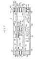
- the bolster main body 1 is integrally composed of a driving bolster member 10 mounted to a bolster mounting portion"A100" of a forging press apparatus "A", a driven bolster apparatus 14 also mounted to the bolster mounting portion "A100” of the forging press apparatus “A”, and a die holding portion 17 disposed between the driving bolster member 10 and the driven bolster member 14.
- the driving bolster member 10 is provided with mounting bores 10a constituting a mounting portion, and mounted detachably to the mounting portion "A100" of the forging press apparatus "A” by bolts inserted into the mounting bores 10a.
- the driven bolster member 14 is mounted to the mounting portion "A100" of the forging press apparatus "A” in a similar manner.
- the driving bolster member 10 will be hereinafter described.
- the driving bolster member 10 comprises a front frame 100, main stays 101, sub-stays 102, side frames 104 fixed between the main stays 101 and sub-stays 102 by bolts 103, and a bearing case 105 fixed on the front frame 100.
- the side frames 104 are provided with a reinforcement pin 106 for reinforcing themselves.
- the driven bolster member 14 comprises a front frame 140, main stays 141, sub-stays 142, side frames 144 fixed between the main stays 141 and sub-stays 142 by bolts, and a bearing case 145 fixed on the front frame 140.
- the side frames 144 are provided with a reinforcement pin 146 for reinforcing themselves.
- a workpiece transfer path 17a of the die holding portion 17 has die holding bores 170, 171, 172 and 173 disposed in series.
- a crushing lower half die 174, a rough forging lower half die 175 as a first die, a finish forging lower half die 176 as a second die and a deflashing lower half die 177 as a third die are inserted into and held in the die holding bores 170, 171, 172 and 173, respectively.
- the bolster main body 1 comprises a set of driving transfer claws 2 and a set of driven transfer claws 3 constituting a set of transfer claw.
- the set of driving transfer claws 2 comprises a driving mounting plate 20 and a transfer claw 21, a first transfer claw 22, a second transfer claw 23 and a sweeper 24 as a third transfer claw, all of which are disposed on the driving mounting plate 20.
- the set of driven transfer claws 3 comprises a driven mounting plate 30 and a transfer claw 31, a first transfer claw 32, a second transfer claw 33 and a sweeper 34 as a third transfer claw, all of which are disposed on the driven mounting plate 30.
- FIG. 5 and 6 the first transfer claws 2 and 3 will be hereinafter described.
- bushes 25 and 35 are inserted into holes 22a and 32a of the first transfer claws 2 and 3 respectively.
- Bolts 26 and 36 are inserted into the bushes 25 and 35, and screwed in threaded holes 22b and 32b of the mounting plates 20 and 30 respectively.
- springs 27 and 37 for effecting workpiece gripping operation are interposed between the first transfer claws 22 and the mounting plate 20 and between the first transfer claw 32 and the mounting plate 30 respectively.
- the transfer claws 21 and 31 as well as the second transfer claws 23 and 33 have an identical construction.
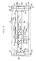
- the bolster main body 1 is provided with a square movement mechanism 4 for actuating the horizontal two-dimensional square movement of the set of driving transfer claws 2 and the set of driven transfer claws 3 and effecting transfer operation.
- the square movement mechanism 4 will be hereinafter described.
- the square movement mechanism 4 comprises a driving mechanism 5 disposed in the driving bolster member 10, a driven mechanism 6 disposed in the driven bolster member 14 and a synchronizing mechanism 7, illustrated in Figure 15, for synchronously transmitting the movement of the driving mechanism 5 to the driven mechanism 6.
- the driving mechanism 5 will be described with reference to Figures 7 through 11.
- the right and left direction of the drawing is taken as the X-direction
- the top and bottom direction is taken as the Y-direction.
- a feed shaft 50 is fixed between the side frames 104 at the right and the side frames 104 at the left by bolts 51.
- a movable feed shaft 52 is held in the side frames 104 at the right by a bearing 520 and a bearing 107 in the bearing case 105, and movable in the axial direction thereof, i.e., the directions of the arrows "X1" and "X2" in Figure 7.
- a movable stand 522 is fixed to the movable feed shaft 52 at the end by a bolt 521.
- the movable stand 522 engages with the set of driving transfer claws 2 and the set of driven transfer claws 3, and moves the set of driving transfer claws 2 and the set of driven transfer claws 3 in the directions of the arrows "X1" and "X2".
- a pneumatic cylinder 53 for advancing and retracting the movable feed shaft 52 is fixed on the front frame 100 of the driving bolster member 10 by fixtures 53a.
- a cylinder rod 530 of the pneumatic cylinder 53 is connected to a motion mixer 54 by a bolt 531a while being interposed by a connector 531, and the motion mixer 54 is connected to the movable feed shaft 52 by a fixture 54a.
- An absorber stopper 55 is further connected to the motion mixer 54.
- the absorber stopper 55 is held movably by the feed shaft 50 while being interposed by a bearing 550.
- the cylinder rod 530 of the pneumatic cylinder 53 is actuated either in the direction of the arrow "X1" or in the direction of the arrow "X2"
- the movable feed shaft 52, the movable stand 522, the motion mixer 54 and the absorber stopper 55 are moved in the same direction.
- An absorber 56 is further provided for absorbing shocks when the absorber stopper 55 bumps into it.
- guide shafts 57 are fixed parallel to the Y-direction in the side frames 104 by bolts 57a.
- Two (2) transfer shafts 58 are connected to the guide shafts 57 by way of bearings 580 and transfer shaft holders 581 in a manner extending in the direction of X-direction and bridging the guide shafts 57 at the right and left. Because the bearings 580 are guided along the guide shafts 57, the transfer shafts 58 are movable in the length direction of the guide shafts 57, i.e., in the Y-direction.
- a pneumatic cylinder 59 for opening and closing i.e., a driver for effecting the movements in the Y-direction
- the pneumatic cylinder 59 is incorporated into the bolster main body 1 in addition to the pneumatic cylinder 53, because this preferred embodiment features the square movement mechanism 4 incorporated into the bolser main body 1.
- This arrangement is advantageous for down-sizing the overall apparatus when compared with a bolster main body 1 into which a motor mechanism is incorporated.
- a cylinder rod 590 of the pneumatic cylinder 59 is connected to a link driving shaft 592 by a bolt 591a while being interposed by a connector 591.
- the link driving shaft 592 is inserted into a holding bore 540 of the motion mixer 54, and the motion mixer 54 is held substantially at the center of the link driving shaft 592.
- two (2) shafts 541 are disposed in the motion mixer 54 in a manner extending in the Y-direction.
- a movable member 543 is held by the shafts 541 while being interposed by bearings 543d.
- a transfer base 544 is further fixed to the movable member 543 by a bolt 543a and a nut 543b.
- the mounting plate 20 of the set of driving transfer claws 2 are fixed to the transfer base 544 by bolts assembled in mounting holes 544a of the transfer base 544. Because bearings 544b of the transfer base 544 is slidable along the transfer shafts 58, the transfer base 544 is movable along the transfer shafts 58 in the X-direction.
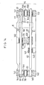
- the driven mechanism 6 of the square movement mechanism 4 will be hereinafter described with reference to Figures 12 through 14.
- the driven mechanism 6 is disposed in the driven bolster member 14, and has a mechanism basically identical with that of the above-mentioned driving mechanism 5 disposed in the driving bolster member 10.
- the driven mechanism 6 differs from the driving mechanism 5 in that no pneumatic cylinder 53 for advancing and retracting and pneumatic cylinder 59 constituting the drivers are provided in the driven mechanism 6.
- a feed shaft 60 is fixed between the side frames 144 at the right and the side frames 144 at the left by bolts 61. Further, a movable feed shaft 62 is held in the side frames 144 at the right by a bearing 620 and a bearing 147 in the bearing case 145, and movable in the axial direction thereof, i.e., the directions of the arrows "X1" and "X2" in Figure 14.
- a motion mixer 64 is fixed to the movable feed shaft 62 while being interposed by a connector 631. The end of the movable feed shaft 62 is connected to the above-mentioned movable stand 522.
- guide shafts 67 are fixed parallel to the Y-direction in the side frames 144.
- Two (2) transfer shafts 68 are connected to the guide shafts 67 by way of bearings 680 and transfer shaft holders 681 in a manner extending in the direction of X-direction and bridging the guide shafts 67 at the right and left.
- the transfer shafts 68 are movable in the length direction of the guide shafts 67, i.e., in the Y-direction.
- a link driving shaft 692 is inserted into a holding bore of the motion mixer 64, and the motion mixer 64 is held substantially at the center of the link driving shaft 692. When the link driving shaft 692 is moved either in the direction of the arrow "Y1" or in the direction of the arrow "Y2", the motion mixer 64 can be moved accordingly.
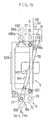
- the synchronizing mechanism 7 for synchronizing the driving mechanism 5 with the driven mechanism 6 will be hereinafter described.
- two (2) synchronizing mechanisms 7 are disposed in the bolster main body 1 at the right and left ends of the X-direction thereof for securing synchronizing performance.
- the synchronizing mechanisms 7 comprise link pins 70 and 71 rotatably engaging with the side frames 104, link plates 72 swingably held by the link pins 70 and 71, and link plates 74 swingably held by the link pins 71 and the link driving shaft 592.
- the synchronizing mechanisms 7 further comprise link plates 77 held swingably by link pins 76 at the center thereof and held by link pins 692a at one end thereof, link plates 693 connecting the link pins 692a and the link driving shaft 692, and synchronizing shafts 78 connecting the driving link plates 72 and the driven link plates 77 by pins 78a and 78b.
- reference numbers 70a's, 71a's and 592a's specify bearings.
- a die mounting member 80 is held by the mounting plate 20 of the set of driving transfer claws 2 and the mounting plate 30 of the set of driven transfer claws 3, and a clamping die 81 is fixed to the die mounting member 80.
- a clamping surface 82 for clamping a finish forged product W3 one of workpieces is formed on the the clamping die 81 in a semicircular arc shape.
- a guide bore 177a is formed on the deflashing lower half die 177, and the clamping die 81 is slidable on the wall surface of the guide bore 177a in the direction of the arrow "T".
- the forging press apparatus "A” to which the above-mentioned bolster apparatus of this preferred embodiment is mounted will be described with reference to Figure 18.
- the forging press apparatus “A” comprises a lower member provided with a knock-out piston 800, knock-out pins 801 and 802, and an upper member provided with a knock-out plate 820, knock-out pins 821, 822, 823 and 824, and a chute 825.
- an upper bolster apparatus 184 is further provided in which a crushing upper half die 184, a rough forging upper half die 185, a finish forging upper half die 186 and a deflashing upper half die 187 are attached.
- the bolster apparatus of this preferred embodiment described above are operated as follows. First, the forging press apparatus "A" is actuated with the following set-up as shown in Figure 18: a workpiece W0 is placed in the crushing lower half die 174, a crushed workpiece W1 which has been crushed and deformed by the crushing lower half die 174 and the crushing upper half die 184 is placed in the rough forging lower half die 175, and a rough forged product W3 which has been molded by the rough forging lower half die 175 and the rough forging upper half die 185 is placed in the finish forging lower half die 176.
- the workpiece W0 is crushed by the crushing lower half die 174 and the crushing upper half die 184
- the crushed workpiece W1 is rough-forged to a rough forged product W2 by the rough forging lower half die 175 and the rough forging upper half die 185
- the rough forged product W2 is finish-forged to a finish forged product W3 by the finish forging lower half die 176 and the finish forging upper half die 186
- the finish forged product W3 is deflashed by the deflashing lower half die 177 and the deflashing upper half die 187.
- the cylinder rod 590 of the pneumatic cylinder 59 of the square movement mechanism 4 for opening and closing, i.e., the Y-direction transfer operates in the direction of the arrow "Y1" to move the link driving shaft 592, the motion mixer 54 and the movable member 543 in the direction of the arrow "Y1" as shown in Figure 8.
- the set of driving transfer claws 2 is moved in the direction of the arrow "Y1" as shown in Figure 11.
- the cylinder rod 530 of the pneumatic cylinder 53 for advancing and retracting, i.e., the X-direction transfer operates to move the motion mixer 54 at the position specified by the alternate long and two dashes lines in Figure 7.
- the transfer base 544 accordingly advances in the direction of the arrow "X1"
- the movable stand 522 fixed at the end of the movable feed shaft 520 advances in the same direction.
- the set of driving transfer claws 2 and the set of driven transfer claws 3 engaging with the movable stand 522 by way of the mounting plates 20 and 30 are advanced in the direction of the arrow "X1".
- the pneumatic cylinder 59 for opening and closing therefor actuate to extend the cylinder rod 590 in the direction of the arrow "Y2" as shown in Figure 8.
- the link driving shaft 592 and the motion mixer 54 move in the direction of the arrow "Y2".
- the link driving shaft 592 moves in the direction of the arrow "Y2” and the transfer base 544 moves in the same direction therewith, the set of the driving transfer claws 2 is opened consequently.
- the transfer claws 21 and 31 release the crushed workpiece W1
- the first transfer claws 22 and 32 release the rough forged product W2
- the second transfer claws 23 and 33 release the finish forged product W3.
- the crushed workpiece W1, the rough forged product W2 and the finish forged product W3 are advanced by a predetermined pitch, i.e., the stroke-length of the pneumatic cylinder 53 for the X-direction transfer, and transferred to the subsequent processing positions.
- the forging press apparatus "A” actuates to move the crushing upper half die 184, the rough forging upper half die 185, the finish forging upper half die 186 and the deflashing upper half die 187 downward. Accordingly, the crushed workpiece W1 is rough-forged to a rough forged product W2, the rough forged product W2 is finish-forged to a finish forged product W3, and the finish forged product W3 is deflashed.
- the clamping surface 82 of the clamping die 81 is away from the deflashing lower half die 177 when the set of driving transfer claws 2 and the set of driven transfer claws 3 are moving in the direction of the arrow "X1".
- the finish forged product W3 are held and transferred by the second transfer claw 23 of the set of driving transfer claws 2 and the second transfer claws 33 of the set of driven transfer claws 3, and placed in the cavity of the deflashing lower half die 177.
- the deflashing upper half die 187 is moved downward to deflash the central bore W30 of the finish forged product W3.
- the sweepers 24 and 34 put into the closing state are advanced in the direction of the arrow "X1", thereby discharging the deflashed finish forged product W3 out to the chute 825 through a guide bore 177a.
- square movement mechanisms 4 can be exchanged automatically by exchanging the bolster main bodies 1.
- the forging press "A” is operated to perform another series of press forming processes to forge and produce the another product.
- the process for press-forming workpieces according to this preferred embodiment is advantageous when producing various products by the small lot, because the square mechanisms 4 constituting transfers can be exchanged automatically be exchanging the bolster apparatuses. It is also understood that the bolster apparatus according to this preferred embodiment has enabled the above-mentioned process for pressing workpieces.
- the driving mechanism 903 of the square movement mechanism 902 is disposed at one end of the workpiece advancement direction, i.e., at one end of the X-direction, and that the driven mechanism 904 of the square movement mechanism 902 is disposed at the other end of the workpiece advancement direction.
- the length of rods 905 connecting the driving mechanism 903 and the driven mechanism 904 increases, and that the inertia masses and inertia forces thereof tend to increase in accordance with the increasing rod 905 length. Consequently, the structures of the rods 905 and the bolster apparatus should be highly strengthened and rigidified.
- this preferred embodiment has the driving mechanism 5 disposed at one end of the Y-direction which intersects the workpiece W transfer direction (the X-direction), and the driven mechanism 6 disposed at the other end of the Y-direction.
- the driving mechanism 5 disposed at one end of the Y-direction which intersects the workpiece W transfer direction (the X-direction)
- the driven mechanism 6 disposed at the other end of the Y-direction.
- the above-mentioned preferred embodiment is an example applied to a forging press process, but can be applied to a sheet metal press process, a deep drawing process and so on. Further, the bolster apparatus according to this invention is not limited to the preferred embodiment described above and illustrated in the drawings.
- This invention relates to a process for press-forming workpieces and a bolster apparatus for the same.
- the process employs a first bolster apparatus comprising a die holding portion and a transfer, and a second bolster apparatus comprising a die holding portion and a transfer.
- the process comprises the steps performed sequentially: an exchanging step of removing the first bolster apparatus from a bolster mounting portion of a pressing apparatus and mounting the second bolster apparatus to a bolster mounting portion of the pressing apparatus, thereby exchanging the first bolster apparatus with the second bolster apparatus; and a press-forming step of press-forming second workpieces with the second dies held in the second bolster apparatus by operating the pressing apparatus.
- the process and the bolster apparatus improve the productivity, and are advantageous when producing various types of products by the small lot, because the transfer can be exchanged simultaneously with the exchange of the bolster apparatuses.
- the bolster apparatus has done away with the base for the transfer, because the transfer is incorporated in the bolster apparatus.
Landscapes
- Engineering & Computer Science (AREA)
- Mechanical Engineering (AREA)
- Forging (AREA)
- Mounting, Exchange, And Manufacturing Of Dies (AREA)
Applications Claiming Priority (6)
| Application Number | Priority Date | Filing Date | Title |
|---|---|---|---|
| JP141645/88 | 1988-10-29 | ||
| JP63274135A JP2502710B2 (ja) | 1988-10-29 | 1988-10-29 | ワ―クプレス成形方法に使用できるボルスタ装置 |
| JP1988141645U JPH0713868Y2 (ja) | 1988-10-29 | 1988-10-29 | 成形型装置 |
| JP274135/88 | 1988-10-29 | ||
| JP142664/88 | 1988-10-31 | ||
| JP14266488U JPH0622509Y2 (ja) | 1988-10-31 | 1988-10-31 | トランスファ装置 |
Publications (3)
| Publication Number | Publication Date |
|---|---|
| EP0367113A2 true EP0367113A2 (fr) | 1990-05-09 |
| EP0367113A3 EP0367113A3 (fr) | 1991-04-03 |
| EP0367113B1 EP0367113B1 (fr) | 1993-08-25 |
Family
ID=27318289
Family Applications (1)
| Application Number | Title | Priority Date | Filing Date |
|---|---|---|---|
| EP89119919A Expired - Lifetime EP0367113B1 (fr) | 1988-10-29 | 1989-10-26 | Table de presse |
Country Status (3)
| Country | Link |
|---|---|
| US (1) | US5074141A (fr) |
| EP (1) | EP0367113B1 (fr) |
| DE (1) | DE68908660T2 (fr) |
Cited By (2)
| Publication number | Priority date | Publication date | Assignee | Title |
|---|---|---|---|---|
| CN109332466A (zh) * | 2018-11-09 | 2019-02-15 | 王洁 | 罐体成型装置、系统和方法 |
| CN111496165A (zh) * | 2020-05-05 | 2020-08-07 | 李素莲 | 一种建筑用材料锻打设备 |
Families Citing this family (8)
| Publication number | Priority date | Publication date | Assignee | Title |
|---|---|---|---|---|
| ES2071469T3 (es) * | 1991-03-15 | 1995-06-16 | Styner & Bienz Ag | Disposicion de transferencia de una prensa. |
| RU2146618C1 (ru) * | 1998-01-29 | 2000-03-20 | Воронежское ЗАО по выпуску тяжелых механических прессов | Грейферная подача к штамповочному прессу |
| US6196044B1 (en) | 1999-11-19 | 2001-03-06 | Hms Products Co. | Press transfer bar-finger support |
| US6196123B1 (en) * | 2000-01-25 | 2001-03-06 | Hms Products Co. | Press transfer-electrical interconnect |
| US6672448B2 (en) * | 2000-03-10 | 2004-01-06 | Aida Engineering Co., Ltd. | Transfer device |
| US7007538B2 (en) * | 2004-06-23 | 2006-03-07 | Hms Products Co. | Breakaway tooling |
| CN107442683B (zh) * | 2017-09-29 | 2019-04-30 | 宁波市鄞州风名工业产品设计有限公司 | 一种冷轧头部成型机 |
| CN111415815B (zh) * | 2020-04-27 | 2024-05-10 | 佛山市南海矽钢铁芯制造有限公司 | 一种矩形磁芯自动挤压成型机的磁芯输送及升降机构 |
Family Cites Families (14)
| Publication number | Priority date | Publication date | Assignee | Title |
|---|---|---|---|---|
| FR902216A (fr) * | 1944-02-17 | 1945-08-22 | Dispositif de distribution automatique des pièces pour outils de découpage, emboutissage, mise en forme, etc., à opérations multiples et simultanées | |
| US3057312A (en) * | 1958-05-21 | 1962-10-09 | Meredith R Hatch | Work feed and drive therefor |
| DE1502861A1 (de) * | 1963-05-11 | 1969-12-04 | Metallwaren Und Maschinenfabri | Werkstueck-Vorschubeinrichtung fuer Pressen od.dgl. |
| US3262541A (en) * | 1964-01-17 | 1966-07-26 | Koppy Tool & Die Company | Drive means for a transfer mechanism |
| US3422657A (en) * | 1966-04-22 | 1969-01-21 | Nat Machinery Co The | Press transfer mechanism |
| GB1250117A (fr) * | 1969-03-07 | 1971-10-20 | ||
| US3707908A (en) * | 1969-12-23 | 1973-01-02 | Schuler Gmbh L | Press equipped with a transfer device |
| US3746184A (en) * | 1971-07-26 | 1973-07-17 | B Wallis | Safety retract mechanism |
| GB1370686A (en) * | 1971-09-17 | 1974-10-16 | Highwood Mechanical Feeds Ltd | Workpiece transfer devices |
| US4032018A (en) * | 1975-11-21 | 1977-06-28 | Wallis Bernard J | Workpiece transfer mechanism |
| DE2814118C2 (de) * | 1978-04-01 | 1982-12-30 | Günter 7500 Karlsruhe Zierpka | Vorschubeinrichtung in Werkzeugmaschinen, insbesondere in Pressen |
| US4428221A (en) * | 1982-01-22 | 1984-01-31 | Owens Roland G | Transfer apparatus for straight side press |
| FR2582241B1 (fr) * | 1985-05-22 | 1987-08-21 | Orflam Expl Ets | Dispositif de transfert de pieces a adjoindre a une machine-outil |
| DD254344A1 (de) * | 1986-12-10 | 1988-02-24 | Warnke Umformtech Veb K | Mechanischer dreidimensionaler antrieb fuer greiferschienen an transferpressen |
-
1989
- 1989-10-26 EP EP89119919A patent/EP0367113B1/fr not_active Expired - Lifetime
- 1989-10-26 DE DE89119919T patent/DE68908660T2/de not_active Expired - Fee Related
- 1989-10-27 US US07/428,060 patent/US5074141A/en not_active Expired - Fee Related
Cited By (2)
| Publication number | Priority date | Publication date | Assignee | Title |
|---|---|---|---|---|
| CN109332466A (zh) * | 2018-11-09 | 2019-02-15 | 王洁 | 罐体成型装置、系统和方法 |
| CN111496165A (zh) * | 2020-05-05 | 2020-08-07 | 李素莲 | 一种建筑用材料锻打设备 |
Also Published As
| Publication number | Publication date |
|---|---|
| US5074141A (en) | 1991-12-24 |
| DE68908660D1 (de) | 1993-09-30 |
| EP0367113B1 (fr) | 1993-08-25 |
| EP0367113A3 (fr) | 1991-04-03 |
| DE68908660T2 (de) | 1994-01-05 |
Similar Documents
| Publication | Publication Date | Title |
|---|---|---|
| US5074141A (en) | Bolster apparatus for press-forming workpieces | |
| CN214639493U (zh) | 一种冷冲压成型的散热冲压件 | |
| JPH01215419A (ja) | プレス用加工片移送組立体 | |
| UA46704C2 (uk) | Спосіб виготовлення порожнистих предметів, зокрема пластмасових заготовок, і пристрій для його здійснення | |
| CN113385582B (zh) | 一种多运程汽车覆盖件模具修整装置 | |
| ITMI20002670A1 (it) | Cassetta di utensili con matrice a molla | |
| CN214866774U (zh) | 多工位冷冲模具钣金工序件模内自动传送装置 | |
| CN112536417B (zh) | 锻造压机 | |
| JP3448199B2 (ja) | 異形長尺品成形用の鍛造プレス | |
| JP2739707B2 (ja) | 多段式圧造成形機 | |
| JP6733896B1 (ja) | 逐次成形装置及び逐次成形方法 | |
| CN214351054U (zh) | 一种工业生产用机械液压夹紧机构 | |
| JPH0713868Y2 (ja) | 成形型装置 | |
| JPH0622509Y2 (ja) | トランスファ装置 | |
| JP2502710B2 (ja) | ワ―クプレス成形方法に使用できるボルスタ装置 | |
| JP2000312927A (ja) | ワークのバリ取り装置 | |
| RU2381861C1 (ru) | Устройство для формообразования изделий с переменным сечением пластическим деформированием | |
| JP3058219U (ja) | 多段式圧造成形機 | |
| CN112547953B (zh) | 多工位冷冲模具钣金工序件模内自动传送装置 | |
| JPH0741545Y2 (ja) | 圧造成形機の押し出しストリッパー駆動装置 | |
| JP2539319Y2 (ja) | 多段式圧造成形機のブランク移送装置 | |
| CN220970473U (zh) | 一种热冲压产品成型用负角翻边机构 | |
| CN117772915B (zh) | 一种载体外壳的冲压弯折装置及系统 | |
| CN218925941U (zh) | 一种汽车车架冲压模具 | |
| JP3049044U (ja) | 圧造成形機の素材移送用チャック装置 |
Legal Events
| Date | Code | Title | Description |
|---|---|---|---|
| PUAI | Public reference made under article 153(3) epc to a published international application that has entered the european phase |
Free format text: ORIGINAL CODE: 0009012 |
|
| 17P | Request for examination filed |
Effective date: 19891026 |
|
| AK | Designated contracting states |
Kind code of ref document: A2 Designated state(s): DE FR GB IT |
|
| PUAL | Search report despatched |
Free format text: ORIGINAL CODE: 0009013 |
|
| AK | Designated contracting states |
Kind code of ref document: A3 Designated state(s): DE FR GB IT |
|
| 17Q | First examination report despatched |
Effective date: 19920214 |
|
| GRAA | (expected) grant |
Free format text: ORIGINAL CODE: 0009210 |
|
| AK | Designated contracting states |
Kind code of ref document: B1 Designated state(s): DE FR GB IT |
|
| PG25 | Lapsed in a contracting state [announced via postgrant information from national office to epo] |
Ref country code: IT Free format text: LAPSE BECAUSE OF FAILURE TO SUBMIT A TRANSLATION OF THE DESCRIPTION OR TO PAY THE FEE WITHIN THE PRE;WARNING: LAPSES OF ITALIAN PATENTS WITH EFFECTIVE DATE BEFORE 2007 MAY HAVE OCCURRED AT ANY TIME BEFORE 2007. THE CORRECT EFFECTIVE DATE MAY BE DIFFERENT FROM THE ONE RECORDED.SCRIBED TIME-LIMIT Effective date: 19930825 Ref country code: FR Effective date: 19930825 |
|
| REF | Corresponds to: |
Ref document number: 68908660 Country of ref document: DE Date of ref document: 19930930 |
|
| EN | Fr: translation not filed | ||
| PLBE | No opposition filed within time limit |
Free format text: ORIGINAL CODE: 0009261 |
|
| STAA | Information on the status of an ep patent application or granted ep patent |
Free format text: STATUS: NO OPPOSITION FILED WITHIN TIME LIMIT |
|
| 26N | No opposition filed | ||
| PGFP | Annual fee paid to national office [announced via postgrant information from national office to epo] |
Ref country code: GB Payment date: 19941010 Year of fee payment: 6 |
|
| PGFP | Annual fee paid to national office [announced via postgrant information from national office to epo] |
Ref country code: DE Payment date: 19941130 Year of fee payment: 6 |
|
| PG25 | Lapsed in a contracting state [announced via postgrant information from national office to epo] |
Ref country code: GB Effective date: 19951026 |
|
| GBPC | Gb: european patent ceased through non-payment of renewal fee |
Effective date: 19951026 |
|
| PG25 | Lapsed in a contracting state [announced via postgrant information from national office to epo] |
Ref country code: DE Effective date: 19960702 |