EP0367176B1 - Unité de panneau d'intérieur permettant la disposition de câbles et d'équipements techniques sur le sol - Google Patents
Unité de panneau d'intérieur permettant la disposition de câbles et d'équipements techniques sur le sol Download PDFInfo
- Publication number
- EP0367176B1 EP0367176B1 EP89120096A EP89120096A EP0367176B1 EP 0367176 B1 EP0367176 B1 EP 0367176B1 EP 89120096 A EP89120096 A EP 89120096A EP 89120096 A EP89120096 A EP 89120096A EP 0367176 B1 EP0367176 B1 EP 0367176B1
- Authority
- EP
- European Patent Office
- Prior art keywords
- floor
- members
- support members
- connecting support
- panel unit
- Prior art date
- Legal status (The legal status is an assumption and is not a legal conclusion. Google has not performed a legal analysis and makes no representation as to the accuracy of the status listed.)
- Expired - Lifetime
Links
Images


Classifications
-
- E—FIXED CONSTRUCTIONS
- E04—BUILDING
- E04F—FINISHING WORK ON BUILDINGS, e.g. STAIRS, FLOORS
- E04F15/00—Flooring
- E04F15/02—Flooring or floor layers composed of a number of similar elements
- E04F15/024—Sectional false floors, e.g. computer floors
- E04F15/02447—Supporting structures
- E04F15/02494—Supporting structures with a plurality of base plates or like, each base plate having a plurality of pedestals upstanding therefrom to receive the floor panels
-
- E—FIXED CONSTRUCTIONS
- E04—BUILDING
- E04F—FINISHING WORK ON BUILDINGS, e.g. STAIRS, FLOORS
- E04F15/00—Flooring
- E04F15/02—Flooring or floor layers composed of a number of similar elements
- E04F15/02172—Floor elements with an anti-skid main surface, other than with grooves
-
- E—FIXED CONSTRUCTIONS
- E04—BUILDING
- E04F—FINISHING WORK ON BUILDINGS, e.g. STAIRS, FLOORS
- E04F15/00—Flooring
- E04F15/02—Flooring or floor layers composed of a number of similar elements
- E04F15/024—Sectional false floors, e.g. computer floors
- E04F15/02405—Floor panels
-
- H—ELECTRICITY
- H02—GENERATION; CONVERSION OR DISTRIBUTION OF ELECTRIC POWER
- H02G—INSTALLATION OF ELECTRIC CABLES OR LINES, OR OF COMBINED OPTICAL AND ELECTRIC CABLES OR LINES
- H02G3/00—Installations of electric cables or lines or protective tubing therefor in or on buildings, equivalent structures or vehicles
- H02G3/28—Installations of cables, lines, or separate protective tubing therefor in conduits or ducts pre-established in walls, ceilings or floors
- H02G3/283—Installations of cables, lines, or separate protective tubing therefor in conduits or ducts pre-established in walls, ceilings or floors in floors
- H02G3/285—Installations of cables, lines, or separate protective tubing therefor in conduits or ducts pre-established in walls, ceilings or floors in floors in modular floors, e.g. access floors
Definitions
- the present invention relates to, an interior panel unit for permitting an arrangement of cables and devices on the floor of a room, including a floor base member to be installed on a foundation floor of the room, a plurality of fundamental support members fixed to an upper surface of each of said floor base member, and having upper surfaces located at the same height from said upper surface of each floor base member; a plurality of connecting support members fixed to peripheral portions of each floor base member, and having upper surfaces located the same height as those of said fundamental support members; base joint members for connecting said connecting support members arranged on a plurality of said floor base members in a state wherein the floor base members are installed on the same surface; and floor panel members mounted on said plurality of fundamental support members and said connecting support members to form a surface of the room floor and cooperating with said floor base members to define an internal space for installing cables and devices therein.
- a conventional interior panel unit is available to realize an office-automation system by arranging power cables, signal cables, and various types of equipment on a room floor in an office or computer room, as described in U.S.P Nos. 4,593,499 and 4,631,879.
- a given unit has blocks having shapes to be engaged with each other at a peripheral portion of a rectangular floor base installed on a foundation floor surface of a room, and blocks on each floor base are engaged with and coupled to each other to form each floor base on the foundation floor surface.
- a plurality of columnar members are mounted on a lower floor base installed on a foundation floor surface, and an upper floor base is supported by the columnar members with a gap corresponding to the height of each columnar member from the foundation floor surface.
- the latter unit has a structure wherein the lower floor base is installed on the foundation floor surface of the room and the upper floor base is supported and fixed through the plurality of columnar members.
- the adjacent lower floor bases are not coupled to each other. For this reason, the lower floor bases are not integrally coupled. Therefore, when the upper floor base is supported and fixed, stability and flatness of the upper floor surface consisting of the upper floor bases are degraded.
- the WO-A 87 03 324 discloses an interior panel unit comprising fundamental support members and connecting support members which are fixed to floor base members and which support floor panel members to form a surface of the room floor.
- Base joint members are provided for connecting the connecting support members.
- a corner joining fastener serves as a base joint member for four adjacent quarter-pieces of connecting support members and engages into recessive in the connecting support members from the top.
- the corner joining fastener constitutes an intermediate member between the support member and the floor panel member.
- the half-pieces of the connecting support members are connected together by means of a bracket extending from one half-piece which is received in recess in the adjacent half-piece support member.
- the structure disclosed in this document has to be manufactured with high precision in order to achieve the required stability, and the shape of the respective support members is considerably complex. Moreover, this structure does not always guarantee that the surfaces of all support members have an identical height.
- a panel unit which comprises support members having guide grooves into which connecting bars are fitted for connecting the support members together.
- the object of the present invention is to provide an interior panel unit for permitting an arrangement of cables and devices on a room floor, wherein an installation operation can be simplified, operability can be improved, and stability and flatness of an upper floor surface upon installation can be improved.
- the base joint member comprises a ring-like member which is fitted on a combination of said connecting support members when the plurality of floor base members are connected to each other and which is removed from the combination when said connecting support members are separated from each other; and the floor panel members are brought into contact with said upper surfaces of said plurality of fundamental support members and said upper surfaces of said connecting support members.
- Fig. 1 is a view showing an overall structure of an interior panel unit according to the present invention.
- the unit comprises floor base members 1 installed on a foundation floor surface 4 which defines a space of an office or computer room.
- Each floor base member 1 consists of a flexible synthetic resin (e.g., polypropylene) as a base material and comprises a rectangular plate having a ratio of a long side to a short side of 2 : 1 (e.g., 1 m : 500 mm).
- a flexible synthetic resin e.g., polypropylene
- Fundamental support members (fundamental columns) 11 for supporting a floor panel member 2 are located on the surface of the floor base member 1 except for the edge at predetermined intervals.
- Connecting support members (connecting columns) 12 are located at the edge except for corners of the upper surface of the floor base member 1.
- Connecting support members 13 are located at the corners of the upper surface of the floor base member 1.
- the support members 11 to 13 consist of a fire-retardant material such as foamed concrete and have the same height. It should be noted that 10 fundamental support members 11, 14 connecting support members 12 extending at the edge except for the corners, and four connecting support members 13 at the four corners are formed on each floor base member 1.
- Each fundamental support member 11 comprises a truncated cone and has a recess 11a at almost the center of the upper surface which is to contact the surface of the floor panel member 2.
- the recess 11a serves to prevent lateral shift of the floor panel member 2.
- Each connecting support member 12 extending at the edge except for the corners consists of a half piece which is obtained by cutting a truncated cone corresponding to the fundamental support member 11 in the vertical direction (i.e., a direction perpendicular to the surface of the floor base member 1).
- Each connecting support member 13 extending at each corner of each floor base member 1 comprises a 1/4 piece obtained by cutting the conical member corresponding to the fundamental support member 11 in the vertical directions.
- a slit-like vertical groove 11b is formed in the circumferential wall of each of the support members 11 to 13.
- the vertical grooves 11b are formed to support both ends of a vertical separator member 9 bridged between the adjacent ones of the support members 11 to 13.
- the vertical separator member 9 is a plate member for partitioning the horizontal space on the surface of the floor base member 1.
- V-shaped grooves (to be referred to as V-grooves hereinafter) 14a are formed in the surface of the floor base member 1 to connect the adjacent ones of the support members 11 to 13 with lines on a line obtained by connecting the middle points of the long sides and diagonal lines within each one of rectangles (squares) obtained by dividing the rectangular area into halves.
- Grooves 14b are formed to surround the 1/2 bottom arc of the fundamental support member 11 and the entire bottom arc of the connecting support member 12 extending at the edge, and a groove 14c is also formed to surround the entire bottom arc of the connecting support member 13 extending at each corner.
- the grooves 14a to 14c serve as guide grooves for discharging leaking water.
- Guide holes 15 are formed in the V-grooves 14a at predetermined intervals to discharge water to the foundation floor surface.
- the floor panel member 2 is a member supported by the support members 11 to 13 of the floor base member 1 to constitute an upper floor surface of the room.
- Each floor panel member 2 consists of a rectangular (square) plate member having an area 1/2 that of each floor base member 1. More specifically, each side of the square of the floor panel member 2 is, e.g., 500 mm.
- a circular opening 21 is formed at almost the center of each floor panel member 2. Rectangular notches 22 are formed at opposite sides of each floor panel member 2.
- the circular opening 21 is used to set various devices such as a circular blank piece 211, a floor outlet 212, an address panel 213, and a light-accumulating panel (nighttime marker lamp) 214.
- Each rectangular notch 22 is used to install various devices such as a rectangular blank piece 221, a floor outlet 222, and a partition joint part (partition connecting piece) 223.
- a projection is formed on the lower surface (i.e., a surface which is brought into contact with the support members 11 to 13) of the floor panel member 2 to engage with the recess 11a formed on almost the center of the upper surface of the corresponding fundamental support member 11.
- a floor carpet 3 is installed on the surface of the floor panel member 2.
- the floor carpet 3 consists of a fire-retardant material and has a size corresponding to the area of the floor panel member 2.
- the floor carpet 3 has an arbitrary shape in accordance with the circular opening 21 and rectangular notches 22 formed in the floor panel member 2.
- the adjacent connecting support members 13 extending at the four corners are connected to each other by base joint members 7.
- Each base joint member 7 is engaged with a truncated cone obtained by combining four adjacent connecting support members 13 to connect these connecting support members 13.
- the adjacent connecting support members 12 extending at edges of the adjacent floor base members 1 are connected by the corresponding base joint members 7.
- the plurality of adjacent floor base members 1 are connected by the base joint members 7.
- Horizontal separator members 8 are prepared to partition the space defined by the floor panel members 2 and the floor base members 1 so as to partition the space vertically.
- Each horizontal separator member 8 comprises a plate member which is engaged with four adjacent fundamental support members 11 extending on the surface of the floor base member 1 to partition the vertical space.
- Four holes each having a diameter slightly larger than that of the hole almost at the center of the frustoconical support member 11 are formed on the vertical separator member 8 so that the vertical separator member 8 is supported almost at the centers of the corresponding fundamental support members 11.
- network devices 10 connected to, e.g., signal and power cables can be three-dimensionally arranged between the floor panel members 2 and the floor base members 1.
- Boarder fundamental members 4 are installed on the foundation floor surface of the room at these corners.
- Each boarder fundamental member 4 comprises a strip member having a rectangular wave shape and a predetermined width.
- a plurality of boarder fundamental members 4 are combined in accordance with the size of a boarder area where the floor base members 1 and the floor panel members 2 cannot be installed.
- the plurality of boarder fundamental members 4 are installed in this boarder area.
- a boarder support joint 4a is fitted in a joint mounting groove 41 formed in each boarder fundamental member 4, so that the boarder fundamental members 4 can be integrally formed.
- a boarder floor panel 5 is installed on the upper surface of each border fundamental member 4.
- the boarder floor panel 5 has longitudinal grooves so that it can be cut to obtain a desirable width in accordance with the boarder area.
- a boarder floor carpet 6 similar to the floor carpet 3 is installed on the boarder floor panel 5.
- Fig. 2 is a view showing an arrangement of the floor base member 1 according to the first embodiment.
- a plurality of floor base members 1 are arranged on a foundation floor surface of a room.
- connecting support members 12 of the adjacent floor base members 1 are brought into contact to constitute truncated cones.
- the adjacent connecting support members 12 are connected by the base joint members 7.
- Four adjacent connecting support members 13 at the adjacent corners of the four floor base members 1 are combined to constitute a truncated cone which is then connected by the base joint member 7. Therefore, the adjacent floor base members 1 can be connected to each other and are firmly fixed to each other. Therefore, when the floor panel members 2 are intalled as the entire upper surface of the floor base members 1, stability of the floor panel members 2 can be assured.
- Figs. 3A to 3C, Figs. 4A and 4B, and Figs. 5 and 6 are views respectively showing modifications of the coupling support member and the base joint member of the first embodiment.
- the connecting support member 13 extending at each corner of the floor base member 1 may be a 1/4 piece (one of pieces 33a to 33d) shown in Fig. 3A or a 1/4 piece (one of pieces 34a to 34d) in Fig. 3B.
- the connecting support member 12 extending at the edge except for any corner of the floor base member 1 comprises a 1/2 piece (one of pieces 32a and 32b), as shown in Fig. 3C.
- base joint members e.g., a rectangular ring
- the connecting support member 13 extending at any corner of the floor base member 1 may be a 1/4 piece (one of pieces 40a to 40d) obtained by dividing a member 40 (Fig. 4A) into quarters.
- the base joint member comprises a member 42 having a shape to fit with a cross guide groove 41 formed on the upper surface of the member 40, as shown in Fig. 4A.
- the connecting support member 12 extending at the edge except for any corner may be a 1/2 piece (one of pieces 43a and 43b) of a member 43 shown in Fig. 4B.
- the base joint member comprises a member 44 having a shape to fit in a guide groove 45 formed on the upper surface of the member 43, as shown in Fig. 4B.
- the connecting support member 13 extending at any corner comprises a 1/4 piece (one of pieces 50a to 50d) obtained by dividing a member 50 (Fig. 5) into quarters.
- the base joint member 52 has a shape to fit in a ring-like groove 51 formed on the upper surface of the member 50.
- the member 52 has a central recess and a ring-like peripheral projection fitted in the ring-like groove 51.
- a 1/2 piece of the member 50 shown in Fig. 5 may be used as the connecting support member 12 extending at the edge except for the corner. In this case, when the two connecting support members 12 are combined, the member 50 is constituted.
- the member 52 is fitted in the ring-like groove 51 to connect adjacent connecting support members 12.
- Fig. 7 shows a modification of the floor panel member according to the first embodiment.
- This floor panel member has nine pieces 70a to 70i connected through thin adhesive sheets, and the adhered nine pieces constitute a standard member. Any of the pieces 70a to 70i can be removed as needed.
- floor panel members as a combination obtained by using a plurality of pieces having the circular openings 21 and the rectangular notches 22, a panel shape can be arbitrarily changed.
- Figs. 8 to 11 are views showing the second embodiment.
- a projection 21a engaged with a recess 11a formed on almost the center of the upper surface of a fundamental support member 11 is formed on the lower surface of a floor panel member 2.
- the recess 11a serves to prevent lateral shift.
- damping members (cushion members consisting of, e.g., rubber) which are brought into tight contact with the upper surface of the fundamental support member 11 are formed at four peripheral portions of the projection 21a on the lower surface of the floor panel member 2.
- Fig. 9 is a plan view showing a modification of the above structure of the upper surface of the fundamental support member 11.
- Vertical grooves 11b are formed on the circumferential surface of the fundamental support members 11 to support both ends of a vertical separator member 9.
- the vertical separator member 9 comprises a plate member for partitioning the horizontal space on the surface of the floor base 1.
- a plurality (e.g., four) of recesses 90a to 90d are formed on the upper surface of the fundamental support member 11.
- a plurality of (e.g., four) projections 100 which respectively engage with the recesses 90a to 90d are formed on the lower surface of the floor panel member 2, as shown in Fig. 10.
- Damping members 23 are formed around the projections 100 on the lower surface of the floor panel member 2.
- Fig. 11 is a view showing the lower surface (i.e., a surface which is brought into contact with the foundation floor surface of the room) of the floor base member 1.
- a plate-like rubber member 16 having a three-dimensional pattern for preventing slippage on its surface is adhered to the lower surface of the floor base member 1.
- Figs. 12A to 14C are views showing the third embodiment of the present invention.
- slit-like vertical grooves 11b, 12b, and 13b are respectively formed on the circumferential wall surfaces of fundamental support members 11 and connecting support members 12 and 13, all of which extend on a floor base member 1.
- the vertical grooves 11b, 12b, and 13b are used to support both ends of vertical separator members 9 bridged between the adjacent support members 11 to 13 (Fig. 12B).
- Each vertical separator member 9 comprises a plate member to partition a horizontal space on the surface of the floor base member 1.
- a horizontal separator 8 is prepared to partition the vertical space.
- Each horizontal separator member 8 comprises a plate member and is normally engaged with four adjacent fundamental support members 11 formed on the surface of the floor base member 1 to partition the vertical space.
- Four holes each having a diameter slightly larger than the hole at the center of the frustoconical support member 11 are formed at four corners of the horizontal separator member 8.
- the horizontal separator member 8 is engaged with the adjacent fundamental support member 11 and the connecting support members 12 and 13 to partition the vertical space.
- Figs. 14A to 14C are views showing box-like separator members 80 to 82 as modifications of the vertical or horizontal separator member.
- the box-like separator members 80 to 82 are made of a metal such as aluminum.
- the box-like separators 80 to 82 have four corners 80a to 80d which are brought into contact with the peripheral surfaces of the four adjacent fundamental support members 11 so as to conform to the circumferential surfaces.
- the box-like separator member 80 shown in Fig. 14A does not have side surfaces corresponding to those of the vertical separator member 9 and is used as a horizontal separator member 8.
- Figs. 15A to 16 are views showing the fourth embodiment.
- a floor panel member 2 comprises a foamed metal base member 231, a cover member 232 consisting of a punching metal and formed on the upper surface of the base member 231, and a cover member 233 consisting of a punching metal and formed on the lower surface of the base member 231.
- a floor reinforced by the cover members 232 and 233 and having an excellent ventilation property can be obtained.
- the floor panel member 2 comprises a base member 241 of a honeycomb structure consisting of a foamed metal, a ceramic, a metal plate of aluminum or the like, or paper.
- a cover member 242 consisting of a punching metal is formed on the upper surface of the base member 241.
- a reinforcing member 243 consisting of carbon fibers is formed on the lower surface of the base member 241.
- a floor carpet 3 is installed on the upper surface of the cover member 242.
- Figs. 17A and 17B are views of the fifth embodiment.
- a fundamental support member 11 and connecting support members 12 and 13 extend on a floor base member 1 to support a floor panel member 2.
- V-grooves 14a are formed on the surface of the floor base member 1 by a line connecting middle points of the long sides of the floor base member 1 and diagonals of rectangles (squares) of the rectangular floor base member 1 so as to connect between the support members 11 to 13.
- Grooves 14b are formed to surround a 1/2 bottom arc of each fundamental support member 11 and the entire bottom arc of each connecting support member 12.
- a groove 14c is also formed to surround the entire bottom arc of each connecting support member 13 extending at any corner.
- the grooves 14a to 14c serve as guide grooves for discharging leaking water.
- Guide holes 15 for discharging the leaking water to the foundation floor surface are formed in the V-grooves 14a at predetermined intervals (Fig. 17B). With this structure, water leaking on the upper surface of the floor base member 1 is guided to the guide holes 15 through the grooves 14a to 14c, thereby effectively discharging water to the foundation floor surface. Therefore, the cables and various devices arranged between the floor base member 1 and the floor panel member 2 can be protected from any trouble caused by water leakage, thereby maintaining a stable system operation.
- wiring patterns P for detecting water leakage are formed at both sides of the V-groove 14a to constitute a water leakage sensor.
- the wiring patterns P are connected to a sensor circuit 170 arranged at a predetermined position of the floor base member 1.
- the sensor circuit 170 outputs a detection signal to drive, e.g., a buzzer unit.
- the wiring patterns P may be formed near other grooves 14b and 14c in addition to the portions adjacent to the V-groove 14a.
- Figs. 18A to 19 are views showing the sixth embodiment of the present invention.
- a fan unit F is mounted utilizing a circular opening 21 of a floor panel member 2 to constitute a ventilation system.
- the fan unit F is held by a device support mechanism 180 provided to the lower surface of a floor panel member 2.
- a vent port 181 is formed on the upper surface of the floor panel member 2.
- a ventilation duct is formed between the floor base member 1 and the floor panel member 2.
- the ventilation duct, the fan unit F, and the vent port 181 constitute a ventilation system (or air-conditioning system).
- a basket B corresponding to a device support mechanism 180 is formed on the lower surface of a floor panel member 2 by utilizing a circular opening 21.
- an insecticide or desiccant may be stored in the basket B to kill harmful insects entering the space between the floor base member 1 and the floor panel member 2 or remove humidity. Therefore, a good environment can be maintained for the cables and various devices arranged between the floor base member 1 and the floor panel member 2.
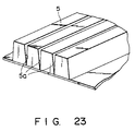
- Figs. 20 to 23 are views showing the seventh embodiment.
- floor base members 1, floor panel members 2, and floor carpets 3 are sequentially installed on a foundation floor surface of a room 190 to constitute an upper floor surface of the room 190.
- Boarder fundamental members 4 are installed on the foundation floor surface of the room 190 at this location (i.e., a boarder area).
- Each boarder fundamental member 4 comprises a strip member having a rectangular wave shape and a predetermined width.
- a plurality of boarder fundamental members 4 are combined in accordance with the size of the boarder area and are installed in the boarder area. In this case, as shown in Fig.
- the boarder columnar joint 4a is fitted in the joint mounting groove 41 arranged in each boarder fundamental member 4, so that the boarder fundamental members 4 are integrally formed.
- a boarder floor panel 5 is placed on the upper surface of each boarder fundamental member 4.
- the boarder floor panel 5 has longitudinal grooves which can be cut to have a predetermined width in accordance with the size of the boarder area.
- a boarder floor carpet 6 similar to the floor carpet 3 is placed on the upper surface of the boarder floor panel 5.
- the boarder fundamental member 4 may have a strip member having a corrugated shape, as shown in Fig. 21A. As shown in Fig. 21B, a joint mounting groove 41 and semispherical openings 42 for wiring may be formed in the corrugated boarder fundamental member 4. When the signal or power cables are installed on the foundation floor surface of the room 190, each cable extends through the opening 42 as needed.
- the boarder fundamental member 4 may have a comb-like shape. When a plurality of comb-like boarder fundamental members 4a and 4b are combined, an inter-digital pattern is formed, as shown in Fig. 22B.
- the boarder floor panel 5 has longitudinal grooves 5a so as to be cut to have a predetermined width, as shown in Fig. 23. Therefore, the boarder floor panel 5 is cut at a predetermined longitudinal groove 5a in accordance with the size of the boarder area, thereby forming a boarder floor panel 5 having an optimal size.
- the floor surface of the room can be formed together with the members 1 to 3 in the boarder area where the members 1 to 3 of the room cannot be installed.
Landscapes
- Engineering & Computer Science (AREA)
- Architecture (AREA)
- Civil Engineering (AREA)
- Structural Engineering (AREA)
- General Engineering & Computer Science (AREA)
- Floor Finish (AREA)
- Installation Of Indoor Wiring (AREA)
Claims (14)
- Ensemble à panneau interne destiné à permettre la disposition de câbles et de dispositifs sur le plancher d'une pièce, comprenant un organe (1) de base de plancher destiné à être installé sur un sol de fondation de la pièce,
plusieurs organes (11) de support fondamental fixés à la surface supérieure de chaque organe (1) de base de plancher et ayant des surfaces supérieures qui se trouvent à la même hauteur par rapport à la surface supérieure de chaque organe (1) de base de plancher,
plusieurs organes (12, 13) de support et de raccordement fixés aux parties périphériques de chaque organe (1) de base de plancher et ayant leurs surfaces supérieures à la même hauteur que celles des organes (11) de support fondamental,
des organes (7) de raccord de base destinés à raccorder des organes (12, 13) de support de raccordement de plusieurs organes (1) de base de plancher dans un état dans lequel les organes de base de plancher sont placés sur la même surface, et
des organes (2) à panneau de plancher montés sur les organes (11) de support fondamental et les organes (12, 13) de support de raccordement pour la formation d'une surface du plancher de la pièce et coopérant avec les organes (1) de base de plancher pour la délimitation d'un espace interne d'installation de câbles et de dispositifs,
caractérisé en ce que l'organe (7) de raccordement de base comporte un organe de forme annulaire qui est monté sur la combinaison des organes (12, 13) de support de raccordement lorsque plusieurs organes (1) de base de plancher sont raccordés mutuellement, et qui est retiré de cette combinaison lorsque les organes (12, 13) de support de raccordement sont séparés les uns des autres, et
les organes (2) de panneau de plancher sont mis en contact avec la surface supérieure des organes (11) de support fondamental et des surfaces supérieures des organes (12, 13) de support de raccordement. - Ensemble à panneau interne selon la revendication 1, caractérisé en ce que les organes (12, 13) de support de raccordement comprennent des premiers organes (13) de support de raccordement formés de quarts obtenus par découpe d'un corps plein en direction perpendiculaire à une surface de l'organe (1) de base de plancher, et des seconds organes (12) de support de raccordement formés par des moitiés obtenus par découpe du corps plein en direction perpendiculaire à la surface de l'organe (1) de base de plancher.
- Ensemble à panneau interne selon la revendication 2, caractérisé en ce que le premier organe (13) de support de raccordement a une gorge de guidage (41) formée à une surface supérieure du quart de corps plein (40), l'organe (42) de raccordement de base est placé dans la gorge de guidage (41) afin qu'elle forme le même plan que la surface supérieure du corps plein (40), si bien que les premiers organes (13) de support de raccordement sont raccordés lorsque les organes (1) de base de plancher sont raccordés mutuellement.
- Ensemble à panneau interne selon la revendication 2, caractérisé en ce que le second organe (12) de support de raccordement a une gorge (45) de guidage à une face supérieure du quart de corps plein (43), et l'organe de raccordement de base (44) est logé dans la gorge de guidage, (45) afin qu'elle donne le même plan que la surface supérieure du corps plein (43) et assure ainsi la connexion des seconds organes (12) de support de raccordement lorsque plusieurs organes (1) de base de plancher sont raccordés les uns aux autres.
- Ensemble à panneau interne selon la revendication 1, caractérisé en ce que l'organe (2) de panneau de plancher comprend un organe de base (241) ayant une structure en nid d'abeilles donnant une propriété de ventilation, et un organe (242) de couvercle formé de métal poinçonné constituant l'une au moins des surfaces supérieure et inférieure de l'organe de base (241).
- Ensemble à panneau interne selon la revendication 1, caractérisé en ce que l'organe (2) de panneau de plancher comprend un organe de base (231) de métal mis en forme ayant une propriété de ventilation, et un organe (232, 233) formant couvercle formé de métal poinçonné à l'une au moins des surfaces supérieure et inférieure de l'organe de base (231).
- Ensemble à panneau interne selon la revendication 1, comprenant en outre des gorges (14a-14c) de guidage d'eau qui a pu fuir, formées sur les organes (1) de base de plancher le long de lignes obtenues par connexion des organes (11) de support fondamental ou des organes (12, 13) de support de raccordement.
- Ensemble à panneau interne selon la revendication 7, comprenant en outre des trous de guidage (15) formés dans les gorges (14a-14c) de guidage d'eau qui peut fuir afin que l'eau qui a pu fuir soit guidée vers la surface du sol de fondation.
- Ensemble à panneau interne selon la revendication 7, comprenant en outre un capteur (P) formé à un bord de la gorge (14a-14c) de guidage d'eau qui a pu fuir à la surface supérieure de l'organe (1) de base de plancher, afin qu'il détecte les fuites d'eau.
- Ensemble à panneau interne selon la revendication 1, comprenant en outre :
un trou (21) de montage de dispositif formé dans l'organe (2) de panneau de plancher, et
un mécanisme (180, B) de support de dispositif formé à la surface inférieure de l'organe (2) de panneau de plancher et destiné au montage de divers dispositifs en position correspondant au trou (21) de montage de dispositif. - Ensemble à panneau interne selon l'une quelconque des revendications précédentes, caractérisé en ce qu'il comprend :
une première partie (11a, 90a-90d) de coopération anti-glissement formée à la surface supérieure de chacun de plusieurs organes (11) de support fondamental, et
une seconde partie (21a, 100) de coopération anti-glissement, formée à la surface inférieure de l'organe de panneau de plancher et coopérant avec la première partie (11a, 90a-90d) de coopération anti-glissement lorsque l'organe (2) de panneau de sol est mis au contact de la surface supérieure de chacun de plusieurs organes (11) de support fondamental et est supporté par cette surface. - Ensemble à panneau interne selon l'une quelconque des revendications précédentes, caractérisé en ce qu'il comprend en outre :
un organe d'amortissement (23) formé à la surface inférieure de l'organe (2) à panneau de plancher et disposé entre la surface supérieure de chacun des organes (11) de support fondamental et la surface inférieure de l'organe (2) à panneau de plancher lorsque l'organe (2) à panneau de plancher est mis au contact de la surface supérieure de chacun des organes (11) de support fondamental et est supporté par cette surface supérieure. - Ensemble à panneau interne selon l'une quelconque des revendications précédentes, caractérisé en ce qu'il comporte en outre un organe (16) formant une feuille anti-glissement disposée à la surface inférieure de l'organe (1) de base de plancher qui est mise au contact d'une surface de sol de fondation.
- Ensemble à panneau interne selon la revendication 1, caractérisé en ce que les organes (12, 13) de support de raccordement ont une gorge (51) de forme annulaire à leur surface supérieure, et l'organe (52) de forme annulaire, qui est monté sur la combinaison des organes (12, 13) de support de raccordement, possède une cavité centrale et une saillie périphérique annulaire logées dans la gorge annulaire (51).
Applications Claiming Priority (19)
| Application Number | Priority Date | Filing Date | Title |
|---|---|---|---|
| JP275614/88 | 1988-10-31 | ||
| JP275610/88 | 1988-10-31 | ||
| JP142055/88 | 1988-10-31 | ||
| JP63275609A JPH02125064A (ja) | 1988-10-31 | 1988-10-31 | システムフロア |
| JP63275618A JPH02125063A (ja) | 1988-10-31 | 1988-10-31 | システムフロア |
| JP275619/88 | 1988-10-31 | ||
| JP275620/88 | 1988-10-31 | ||
| JP14205588U JPH0262032U (fr) | 1988-10-31 | 1988-10-31 | |
| JP63275610A JPH02125061A (ja) | 1988-10-31 | 1988-10-31 | フロアパネル |
| JP275617/88 | 1988-10-31 | ||
| JP63275619A JPH02125067A (ja) | 1988-10-31 | 1988-10-31 | システムフロア |
| JP63275620A JPH02125068A (ja) | 1988-10-31 | 1988-10-31 | システムフロア |
| JP63275614A JPH02125065A (ja) | 1988-10-31 | 1988-10-31 | フロアベースの支柱構造 |
| JP275609/88 | 1988-10-31 | ||
| JP275618/88 | 1988-10-31 | ||
| JP63275617A JPH02125066A (ja) | 1988-10-31 | 1988-10-31 | システムフロア |
| AU77189/91A AU633434B2 (en) | 1988-10-31 | 1991-05-20 | Interior panel unit for permitting arrangement of cables and devices on room floor |
| AU77185/91A AU633432B2 (en) | 1988-10-31 | 1991-05-20 | Interior panel unit for permitting arrangement of cables and devices on room floor |
| AU77188/91A AU633433B2 (en) | 1988-10-31 | 1991-05-20 | Interior panel unit for permitting arrangement of cables and devices on room floor |
Related Child Applications (2)
| Application Number | Title | Priority Date | Filing Date |
|---|---|---|---|
| EP92108696A Division EP0507353A1 (fr) | 1988-10-31 | 1989-10-30 | Unité de panneau d'intérieur permettant la disposition de câbles et d'équipements techniques sur le sol |
| EP92108696.3 Division-Into | 1992-05-22 |
Publications (3)
| Publication Number | Publication Date |
|---|---|
| EP0367176A2 EP0367176A2 (fr) | 1990-05-09 |
| EP0367176A3 EP0367176A3 (fr) | 1991-04-10 |
| EP0367176B1 true EP0367176B1 (fr) | 1993-09-08 |
Family
ID=27581370
Family Applications (2)
| Application Number | Title | Priority Date | Filing Date |
|---|---|---|---|
| EP89120096A Expired - Lifetime EP0367176B1 (fr) | 1988-10-31 | 1989-10-30 | Unité de panneau d'intérieur permettant la disposition de câbles et d'équipements techniques sur le sol |
| EP92108696A Ceased EP0507353A1 (fr) | 1988-10-31 | 1989-10-30 | Unité de panneau d'intérieur permettant la disposition de câbles et d'équipements techniques sur le sol |
Family Applications After (1)
| Application Number | Title | Priority Date | Filing Date |
|---|---|---|---|
| EP92108696A Ceased EP0507353A1 (fr) | 1988-10-31 | 1989-10-30 | Unité de panneau d'intérieur permettant la disposition de câbles et d'équipements techniques sur le sol |
Country Status (5)
| Country | Link |
|---|---|
| US (1) | US5090169A (fr) |
| EP (2) | EP0367176B1 (fr) |
| AU (1) | AU614436B2 (fr) |
| CA (1) | CA2001808C (fr) |
| DE (1) | DE68908998T2 (fr) |
Cited By (2)
| Publication number | Priority date | Publication date | Assignee | Title |
|---|---|---|---|---|
| USD797957S1 (en) | 2009-08-28 | 2017-09-19 | Progress Profiles S.P.A. | Floor underlayment |
| USD813421S1 (en) | 2009-08-28 | 2018-03-20 | Progress Profiles Spa | Floor underlayment |
Families Citing this family (37)
| Publication number | Priority date | Publication date | Assignee | Title |
|---|---|---|---|---|
| US5187907A (en) * | 1988-10-31 | 1993-02-23 | Kabushiki Kaisha Toshiba | Interior panel unit for permitting arrangement of cables and devices on room floor |
| US5197244A (en) * | 1988-10-31 | 1993-03-30 | Kabushiki Kaisha Toshiba | Interior panel unit for permitting arrangement of cables and devices on room floor |
| US5245805A (en) * | 1988-10-31 | 1993-09-21 | Kabushiki Kaisha Toshiba | Interior panel unit for permitting arrangement of cables and devices on room floor |
| USRE35369E (en) * | 1989-02-03 | 1996-11-05 | Guilford (Delaware) Inc. | Flooring system especially designed for facilities which house data processing equipment |
| EP0488312B1 (fr) * | 1990-11-29 | 1995-01-18 | Kabushiki Kaisha Toshiba | Méthode pour la fabrication d'un système de plancher et base pour système de plancher |
| US5392571A (en) * | 1992-04-02 | 1995-02-28 | Powerflor, Inc. | Pedestal module for raised floor and raised floor |
| US5467609A (en) * | 1993-04-23 | 1995-11-21 | Liebert Corporation | Modular floor sub-structure for the operational support of computer systems |
| DE4324142A1 (de) * | 1993-07-19 | 1995-02-09 | Ika Ind Kunststoff Anwendungen | Plattensystem |
| US5499476A (en) * | 1993-08-31 | 1996-03-19 | Interface, Inc. | Low profile raised panel flooring with metal support structure |
| US5673522A (en) * | 1994-03-25 | 1997-10-07 | Guilford, Inc. | Junction box forlow profile raised panel flooring |
| USRE39097E1 (en) | 1994-03-25 | 2006-05-23 | Guildford (Delaware), Inc. | Metal support framework for low profile raised panel flooring |
| US5675950A (en) * | 1994-03-25 | 1997-10-14 | Guilford (Delaware), Inc. | Metal support framework for low profile raised panel flooring |
| US5713168A (en) * | 1994-03-25 | 1998-02-03 | Guilford (Delaware), Inc. | Junction box for low profile raised panel flooring |
| US5828001A (en) * | 1995-02-15 | 1998-10-27 | Guilford (Delaware), Inc. | Plastic junction box with receptacle boxes |
| JP3638679B2 (ja) * | 1995-03-06 | 2005-04-13 | オーエム機器株式会社 | フリーアクセスフロア |
| DE19612862A1 (de) * | 1996-03-30 | 1997-10-09 | Sicowa Verfahrenstech | Hohlraumboden |
| US6061982A (en) * | 1998-02-27 | 2000-05-16 | Owen; David D. | Raised flooring system and method |
| US6256952B1 (en) | 1998-07-27 | 2001-07-10 | Interface, Inc. | Perforated raised flooring panel |
| US6293062B1 (en) * | 1999-11-30 | 2001-09-25 | Yao-Chung Chen | Incombustible fireproof network elevated floorboard |
| US6370831B1 (en) | 2000-03-06 | 2002-04-16 | Smed International | Raised floor system and method of installing same |
| US7461482B2 (en) * | 2005-04-13 | 2008-12-09 | Cerasi Mark A | Sub-flooring assembly and method |
| US20110047898A1 (en) * | 2009-08-25 | 2011-03-03 | Hudgins David K | Building components and the buildings constructed therewith |
| US8955276B2 (en) * | 2012-01-25 | 2015-02-17 | Steven James Wall | Raised flooring apparatus and system |
| CN104411901A (zh) * | 2012-02-10 | 2015-03-11 | 贾科·瓦尔坦伦 | 绝缘元件和包括该绝缘元件的系统 |
| US10215423B2 (en) | 2014-08-18 | 2019-02-26 | Progress Profiles S.P.A. | Method and apparatus for positioning heating elements |
| CA2958571C (fr) | 2014-08-18 | 2019-12-10 | Progress Profiles Spa | Procede et appareil pour le positionnement d'elements chauffants |
| USD806911S1 (en) | 2015-03-17 | 2018-01-02 | Silcart S.P.A. | Floor underlayment |
| US9726383B1 (en) | 2016-06-17 | 2017-08-08 | Progress Profiles S.P.A. | Support for radiant covering and floor heating elements |
| US10859274B2 (en) | 2016-04-01 | 2020-12-08 | Progress Profiles S.P.A. | Support for radiant covering and floor heating elements |
| USD971449S1 (en) | 2016-04-13 | 2022-11-29 | Progress Profiles S.P.A. | Floor underlayment |
| AU201711371S (en) * | 2017-03-07 | 2017-05-15 | Nxt Ip Pty Ltd | Void former |
| USD1036979S1 (en) | 2020-04-06 | 2024-07-30 | Progress Profiles S.P.A. | Floor underlayment |
| USD1036242S1 (en) | 2020-04-22 | 2024-07-23 | Progress Profiles S.P.A. | Floor underlayment |
| US10928075B1 (en) | 2020-05-28 | 2021-02-23 | Mp Global Products, L.L.C. | Floor heating system including membranes that are configured to be joined together to house a heating cable, and membrane system including such membranes |
| US11892176B2 (en) | 2020-05-28 | 2024-02-06 | Mp Global Products, L.L.C. | Universal membrane configured to be divided to form a base membrane and a cover membrane that is couplable to the base membrane to form an uncoupling membrane for installation between a subfloor and floor tiles |
| USD1036243S1 (en) | 2020-10-09 | 2024-07-23 | Progress Profiles S.P.A. | Floor underlayment |
| USD1101979S1 (en) | 2023-02-07 | 2025-11-11 | Progress Profiles S.P.A. | Floor underlayment |
Family Cites Families (22)
| Publication number | Priority date | Publication date | Assignee | Title |
|---|---|---|---|---|
| DE3001035A1 (de) * | 1980-01-12 | 1981-07-16 | Wolfgang 2000 Hamburg Neubauer | Bausatz fuer einen fussboden |
| JPS59150854A (ja) * | 1983-02-15 | 1984-08-29 | 株式会社東芝 | プレキヤストブロツク |
| JPS59208898A (ja) * | 1983-05-13 | 1984-11-27 | 株式会社東芝 | パネル |
| JPS6043565A (ja) * | 1983-08-18 | 1985-03-08 | 株式会社東芝 | パネル |
| DE3318694C2 (de) * | 1983-05-21 | 1985-09-12 | Franz-Josef 4434 Ochtrup Hagemann | Verfahren zum Herstellen einer aus modulartig zu verlegenden Platten bestehenden Bodenauflage |
| JPS6040472A (ja) * | 1983-08-12 | 1985-03-02 | 近畿電気工事株式会社 | 配線用の床材 |
| JPS6043566A (ja) * | 1983-08-18 | 1985-03-08 | 株式会社東芝 | パネル |
| JPS6043564A (ja) * | 1983-08-18 | 1985-03-08 | 株式会社東芝 | パネル |
| JPS6098044A (ja) * | 1983-10-31 | 1985-06-01 | 株式会社東芝 | フリーアクセスフロア |
| JPS6098043A (ja) * | 1983-10-31 | 1985-06-01 | 株式会社東芝 | パネル |
| JPH0623490B2 (ja) * | 1983-10-31 | 1994-03-30 | 株式会社東芝 | パネル |
| JPS60112954A (ja) * | 1983-11-24 | 1985-06-19 | 株式会社東芝 | パネル |
| JPS60112953A (ja) * | 1983-11-24 | 1985-06-19 | 株式会社東芝 | パネル |
| JPS60192051A (ja) * | 1984-03-12 | 1985-09-30 | 大成建設株式会社 | 建造物の床構造 |
| JPS60195260A (ja) * | 1984-03-15 | 1985-10-03 | 大成建設株式会社 | 床構造 |
| JPS60242252A (ja) * | 1984-05-15 | 1985-12-02 | 株式会社東芝 | パネル |
| JPS6176045A (ja) * | 1984-09-19 | 1986-04-18 | Matsushita Electric Ind Co Ltd | 刷子保持カバ−の取り付け装置 |
| GB8510677D0 (en) * | 1985-04-26 | 1985-06-05 | Huntgreen Ltd | Floor construction |
| EP0245375B2 (fr) * | 1985-11-22 | 1993-12-01 | Cablefloor (Australia) Pty. Ltd. | Systeme de plancher |
| JPS62284854A (ja) * | 1986-05-30 | 1987-12-10 | 共同カイテック株式会社 | フロアパネル装置 |
| DE3781836T2 (de) * | 1986-06-19 | 1993-04-29 | Daiken Trade & Industry | Schwimmender fussboden. |
| US4905437A (en) * | 1988-04-21 | 1990-03-06 | Cablefloor (Australia) Pty. Ltd. | Flooring system and method of providing |
-
1989
- 1989-10-30 CA CA002001808A patent/CA2001808C/fr not_active Expired - Fee Related
- 1989-10-30 EP EP89120096A patent/EP0367176B1/fr not_active Expired - Lifetime
- 1989-10-30 EP EP92108696A patent/EP0507353A1/fr not_active Ceased
- 1989-10-30 DE DE89120096T patent/DE68908998T2/de not_active Expired - Fee Related
- 1989-10-31 AU AU43933/89A patent/AU614436B2/en not_active Ceased
- 1989-10-31 US US07/429,552 patent/US5090169A/en not_active Expired - Lifetime
Cited By (3)
| Publication number | Priority date | Publication date | Assignee | Title |
|---|---|---|---|---|
| USD797957S1 (en) | 2009-08-28 | 2017-09-19 | Progress Profiles S.P.A. | Floor underlayment |
| USD813421S1 (en) | 2009-08-28 | 2018-03-20 | Progress Profiles Spa | Floor underlayment |
| US11846432B2 (en) | 2009-08-28 | 2023-12-19 | Progress Profiles Spa | Method and apparatus for positioning heating elements |
Also Published As
| Publication number | Publication date |
|---|---|
| CA2001808C (fr) | 1993-03-30 |
| US5090169A (en) | 1992-02-25 |
| EP0367176A3 (fr) | 1991-04-10 |
| EP0367176A2 (fr) | 1990-05-09 |
| AU4393389A (en) | 1990-07-19 |
| EP0507353A1 (fr) | 1992-10-07 |
| CA2001808A1 (fr) | 1990-04-30 |
| DE68908998D1 (de) | 1993-10-14 |
| AU614436B2 (en) | 1991-08-29 |
| DE68908998T2 (de) | 1994-03-03 |
Similar Documents
| Publication | Publication Date | Title |
|---|---|---|
| EP0367176B1 (fr) | Unité de panneau d'intérieur permettant la disposition de câbles et d'équipements techniques sur le sol | |
| US5197244A (en) | Interior panel unit for permitting arrangement of cables and devices on room floor | |
| US5245805A (en) | Interior panel unit for permitting arrangement of cables and devices on room floor | |
| US5187907A (en) | Interior panel unit for permitting arrangement of cables and devices on room floor | |
| US5184438A (en) | Interior panel unit for permitting arrangement of cables and devices on room floor | |
| US5323575A (en) | Tile and mounting mat assembly | |
| US5768840A (en) | Integrated utility distribution and panel system | |
| US7120269B2 (en) | Lay-in tile speaker system | |
| US6311440B1 (en) | Floor mounted utility post | |
| US6079177A (en) | Removable ceiling panel assembly | |
| USRE35369E (en) | Flooring system especially designed for facilities which house data processing equipment | |
| AU633433B2 (en) | Interior panel unit for permitting arrangement of cables and devices on room floor | |
| AU633432B2 (en) | Interior panel unit for permitting arrangement of cables and devices on room floor | |
| AU633434B2 (en) | Interior panel unit for permitting arrangement of cables and devices on room floor | |
| JPH07189465A (ja) | 二重床ユニット | |
| JPH081393Y2 (ja) | フリーアクセスフロア | |
| JPH11131765A (ja) | フリーアクセスフロア | |
| JP3231653B2 (ja) | 二重床パネル構造 | |
| JPH0213108B2 (fr) | ||
| JP2515580Y2 (ja) | 床吹出空調装置 | |
| JPH02125065A (ja) | フロアベースの支柱構造 | |
| JPH02125068A (ja) | システムフロア | |
| JPH02125063A (ja) | システムフロア | |
| JPH08218603A (ja) | 二重床 | |
| JPH02125061A (ja) | フロアパネル |
Legal Events
| Date | Code | Title | Description |
|---|---|---|---|
| PUAI | Public reference made under article 153(3) epc to a published international application that has entered the european phase |
Free format text: ORIGINAL CODE: 0009012 |
|
| 17P | Request for examination filed |
Effective date: 19891030 |
|
| AK | Designated contracting states |
Kind code of ref document: A2 Designated state(s): DE FR GB |
|
| PUAL | Search report despatched |
Free format text: ORIGINAL CODE: 0009013 |
|
| AK | Designated contracting states |
Kind code of ref document: A3 Designated state(s): DE FR GB |
|
| 17Q | First examination report despatched |
Effective date: 19911015 |
|
| GRAA | (expected) grant |
Free format text: ORIGINAL CODE: 0009210 |
|
| AK | Designated contracting states |
Kind code of ref document: B1 Designated state(s): DE FR GB |
|
| XX | Miscellaneous (additional remarks) |
Free format text: TEILANMELDUNG 92108696.3 EINGEREICHT AM 30/10/89. |
|
| REF | Corresponds to: |
Ref document number: 68908998 Country of ref document: DE Date of ref document: 19931014 |
|
| ET | Fr: translation filed | ||
| PLBE | No opposition filed within time limit |
Free format text: ORIGINAL CODE: 0009261 |
|
| STAA | Information on the status of an ep patent application or granted ep patent |
Free format text: STATUS: NO OPPOSITION FILED WITHIN TIME LIMIT |
|
| 26N | No opposition filed | ||
| REG | Reference to a national code |
Ref country code: GB Ref legal event code: 746 Effective date: 19980909 |
|
| REG | Reference to a national code |
Ref country code: FR Ref legal event code: D6 |
|
| REG | Reference to a national code |
Ref country code: GB Ref legal event code: IF02 |
|
| PGFP | Annual fee paid to national office [announced via postgrant information from national office to epo] |
Ref country code: FR Payment date: 20021008 Year of fee payment: 14 |
|
| PGFP | Annual fee paid to national office [announced via postgrant information from national office to epo] |
Ref country code: GB Payment date: 20021030 Year of fee payment: 14 |
|
| PGFP | Annual fee paid to national office [announced via postgrant information from national office to epo] |
Ref country code: DE Payment date: 20021031 Year of fee payment: 14 |
|
| PG25 | Lapsed in a contracting state [announced via postgrant information from national office to epo] |
Ref country code: GB Free format text: LAPSE BECAUSE OF NON-PAYMENT OF DUE FEES Effective date: 20031030 |
|
| PG25 | Lapsed in a contracting state [announced via postgrant information from national office to epo] |
Ref country code: DE Free format text: LAPSE BECAUSE OF NON-PAYMENT OF DUE FEES Effective date: 20040501 |
|
| GBPC | Gb: european patent ceased through non-payment of renewal fee |
Effective date: 20031030 |
|
| PG25 | Lapsed in a contracting state [announced via postgrant information from national office to epo] |
Ref country code: FR Free format text: LAPSE BECAUSE OF NON-PAYMENT OF DUE FEES Effective date: 20040630 |
|
| REG | Reference to a national code |
Ref country code: FR Ref legal event code: ST |