EP0367264B1 - Digitaler Videobandrecorder, geeignet zur Bildwiedergabe mit hoher Geschwindigkeit - Google Patents
Digitaler Videobandrecorder, geeignet zur Bildwiedergabe mit hoher Geschwindigkeit Download PDFInfo
- Publication number
- EP0367264B1 EP0367264B1 EP89120304A EP89120304A EP0367264B1 EP 0367264 B1 EP0367264 B1 EP 0367264B1 EP 89120304 A EP89120304 A EP 89120304A EP 89120304 A EP89120304 A EP 89120304A EP 0367264 B1 EP0367264 B1 EP 0367264B1
- Authority
- EP
- European Patent Office
- Prior art keywords
- data
- stage
- coding
- image data
- information
- Prior art date
- Legal status (The legal status is an assumption and is not a legal conclusion. Google has not performed a legal analysis and makes no representation as to the accuracy of the status listed.)
- Expired - Lifetime
Links
Images




Classifications
-
- H—ELECTRICITY
- H04—ELECTRIC COMMUNICATION TECHNIQUE
- H04N—PICTORIAL COMMUNICATION, e.g. TELEVISION
- H04N9/00—Details of colour television systems
- H04N9/79—Processing of colour television signals in connection with recording
- H04N9/797—Processing of colour television signals in connection with recording for recording the signal in a plurality of channels, the bandwidth of each channel being less than the bandwidth of the signal
-
- G—PHYSICS
- G11—INFORMATION STORAGE
- G11B—INFORMATION STORAGE BASED ON RELATIVE MOVEMENT BETWEEN RECORD CARRIER AND TRANSDUCER
- G11B20/00—Signal processing not specific to the method of recording or reproducing; Circuits therefor
- G11B20/10—Digital recording or reproducing
- G11B20/18—Error detection or correction; Testing, e.g. of drop-outs
- G11B20/1806—Pulse code modulation systems for audio signals
-
- G—PHYSICS
- G11—INFORMATION STORAGE
- G11B—INFORMATION STORAGE BASED ON RELATIVE MOVEMENT BETWEEN RECORD CARRIER AND TRANSDUCER
- G11B27/00—Editing; Indexing; Addressing; Timing or synchronising; Monitoring; Measuring tape travel
- G11B27/005—Reproducing at a different information rate from the information rate of recording
-
- H—ELECTRICITY
- H04—ELECTRIC COMMUNICATION TECHNIQUE
- H04N—PICTORIAL COMMUNICATION, e.g. TELEVISION
- H04N19/00—Methods or arrangements for coding, decoding, compressing or decompressing digital video signals
- H04N19/60—Methods or arrangements for coding, decoding, compressing or decompressing digital video signals using transform coding
- H04N19/63—Methods or arrangements for coding, decoding, compressing or decompressing digital video signals using transform coding using sub-band based transform, e.g. wavelets
-
- H—ELECTRICITY
- H04—ELECTRIC COMMUNICATION TECHNIQUE
- H04N—PICTORIAL COMMUNICATION, e.g. TELEVISION
- H04N9/00—Details of colour television systems
- H04N9/79—Processing of colour television signals in connection with recording
- H04N9/80—Transformation of the television signal for recording, e.g. modulation, frequency changing; Inverse transformation for playback
- H04N9/804—Transformation of the television signal for recording, e.g. modulation, frequency changing; Inverse transformation for playback involving pulse code modulation of the colour picture signal components
-
- H—ELECTRICITY
- H04—ELECTRIC COMMUNICATION TECHNIQUE
- H04N—PICTORIAL COMMUNICATION, e.g. TELEVISION
- H04N9/00—Details of colour television systems
- H04N9/79—Processing of colour television signals in connection with recording
- H04N9/80—Transformation of the television signal for recording, e.g. modulation, frequency changing; Inverse transformation for playback
- H04N9/804—Transformation of the television signal for recording, e.g. modulation, frequency changing; Inverse transformation for playback involving pulse code modulation of the colour picture signal components
- H04N9/8042—Transformation of the television signal for recording, e.g. modulation, frequency changing; Inverse transformation for playback involving pulse code modulation of the colour picture signal components involving data reduction
-
- H—ELECTRICITY
- H04—ELECTRIC COMMUNICATION TECHNIQUE
- H04N—PICTORIAL COMMUNICATION, e.g. TELEVISION
- H04N9/00—Details of colour television systems
- H04N9/79—Processing of colour television signals in connection with recording
- H04N9/87—Regeneration of colour television signals
-
- H—ELECTRICITY
- H04—ELECTRIC COMMUNICATION TECHNIQUE
- H04N—PICTORIAL COMMUNICATION, e.g. TELEVISION
- H04N9/00—Details of colour television systems
- H04N9/79—Processing of colour television signals in connection with recording
- H04N9/87—Regeneration of colour television signals
- H04N9/88—Signal drop-out compensation
- H04N9/888—Signal drop-out compensation for signals recorded by pulse code modulation
-
- G—PHYSICS
- G11—INFORMATION STORAGE
- G11B—INFORMATION STORAGE BASED ON RELATIVE MOVEMENT BETWEEN RECORD CARRIER AND TRANSDUCER
- G11B2220/00—Record carriers by type
- G11B2220/90—Tape-like record carriers
-
- H—ELECTRICITY
- H04—ELECTRIC COMMUNICATION TECHNIQUE
- H04N—PICTORIAL COMMUNICATION, e.g. TELEVISION
- H04N19/00—Methods or arrangements for coding, decoding, compressing or decompressing digital video signals
- H04N19/10—Methods or arrangements for coding, decoding, compressing or decompressing digital video signals using adaptive coding
- H04N19/102—Methods or arrangements for coding, decoding, compressing or decompressing digital video signals using adaptive coding characterised by the element, parameter or selection affected or controlled by the adaptive coding
-
- H—ELECTRICITY
- H04—ELECTRIC COMMUNICATION TECHNIQUE
- H04N—PICTORIAL COMMUNICATION, e.g. TELEVISION
- H04N19/00—Methods or arrangements for coding, decoding, compressing or decompressing digital video signals
- H04N19/30—Methods or arrangements for coding, decoding, compressing or decompressing digital video signals using hierarchical techniques, e.g. scalability
-
- H—ELECTRICITY
- H04—ELECTRIC COMMUNICATION TECHNIQUE
- H04N—PICTORIAL COMMUNICATION, e.g. TELEVISION
- H04N5/00—Details of television systems
- H04N5/76—Television signal recording
- H04N5/78—Television signal recording using magnetic recording
- H04N5/782—Television signal recording using magnetic recording on tape
- H04N5/7824—Television signal recording using magnetic recording on tape with rotating magnetic heads
- H04N5/7826—Television signal recording using magnetic recording on tape with rotating magnetic heads involving helical scanning of the magnetic tape
- H04N5/78263—Television signal recording using magnetic recording on tape with rotating magnetic heads involving helical scanning of the magnetic tape for recording on tracks inclined relative to the direction of movement of the tape
- H04N5/78266—Television signal recording using magnetic recording on tape with rotating magnetic heads involving helical scanning of the magnetic tape for recording on tracks inclined relative to the direction of movement of the tape using more than one track for the recording of one television field or frame, i.e. segmented recording
-
- H—ELECTRICITY
- H04—ELECTRIC COMMUNICATION TECHNIQUE
- H04N—PICTORIAL COMMUNICATION, e.g. TELEVISION
- H04N5/00—Details of television systems
- H04N5/76—Television signal recording
- H04N5/78—Television signal recording using magnetic recording
- H04N5/782—Television signal recording using magnetic recording on tape
- H04N5/783—Adaptations for reproducing at a rate different from the recording rate
Definitions
- the present invention relates to a digital video tape recorder (hereinafter referred to as a VTR) and, more specifically, to a digital VTR capable of forming a reproduced image at high speed based on digital video information reproduced by a rotary head while a tape is running in the fast forwarding direction or in the rewinding direction at high speed.
- a VTR digital video tape recorder
- a conventional digital VTR for digitally recording video information error correcting information is added to digital video information at every prescribed period, for example, at every block period provided by dividing 1 field period into some blocks.
- the digital video information with error correcting information added in this manner is rearranged by block unit of information, that is, interleave processing is carried out, in order to prevent continuous missing of reproduced images caused by dropout or the like, and thereafter it is recorded on a magnetic tape by means of a rotary head.
- a digital VTR in accordance with the standard of CCIR is disclosed as an example of such a conventional digital VTR in pp. 14 to 21 of "NHK Giken Geppo (monthly report of NHK laboratory)" published in April, 1986.
- an object of the present invention is to enable formation of a reproduced image at high speed reproduction in a digital VTR.
- the digital VTR in accordance with the present invention comprises a circuit for supplying digital video information; an information separating circuit for separating the digital video information into main information enabling rough formation of the whole image and subinformation forming details of the image to supply the same; a first image processing circuit for carrying out error correcting process to the supplied main information; a second image processing circuit for carrying out error correcting process to the supplied subinformation; and a recording circuit for recording outputs from the first and second information processing circuits on a magnetic tape such that the output from the first video information processing circuit is recorded at the center of each of the recording tracks by n (n is a positive integer) field unit and the outputs from the second information processing circuit are recorded on outer portions on both sides of the central portion of each of the recording tracks.
- n is a positive integer
- the digital VTR further comprises a circuit for reproducing at least main information from the recording tracks while the magnetic tape on which the outputs from the first and second information processing circuits are recorded is running at a high speed, and a circuit for forming video information based on the reproduced main information.
- the video information formed on the reproduced main information is a video signal having a variable rate of reduction, and the rate of reduction of the reproduced image can be changed corresponding to the amount of reproduced main information.
- signals indicative of additional information which is to be displayed on a margin formed around the reduced image derived from the video signal are multiplexed on the video signal.
- a main advantage of the present invention is that a rough reproduced image can be formed based only on the main information reproduced during high speed reproduction, since the main information out of the video information is recorded by n field unit at the center of each of the recording tracks.
- a recording portion of a digital VTR in accordance with a first embodiment of the present invention will be described.
- an analog video signal that is, a signal comprising a luminance signal component Y and two different color difference signal components C1 and C2 are supplied from a video camera or a TV tuner, not shown, to an input terminal 100, which video signal is applied to a TCI (time compressed integration) processing circuit 200 through the input terminal 100.
- the TCI processing circuit 200 compresses on time base the Y signal and the C1 and C2 signals of 1 horizontal period at prescribed ratio, respectively, and time divisionally multiplexes these signals in a prescribed order in 1 horizontal period.
- the analog video signal formed by the time divisional multiplication in this manner is supplied to an information separating circuit 300.
- the information separating circuit 300 separates the applied analog video signal into main information which enables rough formation of the whole image by itself during high speed reproduction, and subinformation forming details of the image.
- Various known methods can be employed for separating the analog video signal into main information and subinformation.
- a hierarchical coding method is employed, as will be described later.
- Such a hierarchical coding method is disclosed in, for example, Y. Yasuda et al. "Still Image Coding and Its Applications", pp. 669 to 675 of volume 71, No. 7, journal of the institute of electronics, information and communication engineers, July, 1988, and in IEEE TRANSACTIONS ON COMMUNICATIONS, VOL. COM-31, No. 4, pp. 532 to 540, P. J. Burt et al. "The Laplacian Pyramid as a Compact Image Code", April, 1983.
- Fig. 3 is a block diagram showing the details of the information separating circuit 300 of Fig. 1 employing such a hierarchical coding method.
- the analog video signal from the TCI processing circuit 200 is converted into a digital video signal by means of an A/D converter 1 to be applied to a primary sub-Nyquist sampling (hereinafter referred to as subsampling) circuit 2 and to a first difference circuit 13.
- the primary subsampling circuit 2 is a known circuit including a two dimensional spatial filter which forms information of a first stage image by limiting high frequency of the applied digital video data to thin out the digital data (data compression), that is, by carrying out subsampling processing, to apply the information to a first memory 3.
- the information of the first stage image stored in the first memory 3 is further applied to a second difference circuit 9 as well as to a secondary subsampling circuit 4.
- the secondary subsampling circuit 4 carries out the above mentioned subsampling process on the applied information of the first stage image to form information of 0th stage image to apply the same to a second memory 5.
- the information of the 0th stage image stored in the second memory 5 is applied to a third coding circuit 6 in which processes such as coding and compression, which will be described later, are carried out so as to reduce the amount (the number of bits) of information.
- the output from the third coding circuit 6 is provided as the data of the 0th stage, which are the main information.
- the 0th stage data are simultaneously applied to a second decoding circuit 7 in which decoding corresponding to the coding process by the third coding circuit 6 is carried out.
- the output from the second decoding circuit 7 is applied to a second interpolating circuit 8 in which interpolation corresponding to the subsampling process by the secondary subsampling circuit 4 is carried out.
- the output from the second interpolating circuit 8 is inputted to a second difference circuit 9 in which subtraction with the information of the first stage image is carried out.
- the resulting difference data are applied to a second coding circuit 10 in which coding and compressing process, which will be described later, is carried out and then they are provided as the first stage data which are the subinformation.
- the first stage data are simultaneously applied to a first decoding circuit 11 in which decoding corresponding to the coding process by the second coding circuit 10 is carried out.
- the output from the first decoding circuit 11 is applied to a first interpolating circuit 12 in which interpolation corresponding to the subsampling process by the primary subsampling circuit 2 is carried out.
- the output from the first interpolating circuit 12 is inputted to the first difference circuit 13 in which subtraction with the original video information is carried out.
- the resulting difference data are applied to a first coding circuit 14 in which coding and compressing process, which will be described later, is carried out, and they are provided as the second stage data which are the subinformation.
- the rate of data compression in the first, second and third coding circuits, 14, 10 and 6 can be changed, respectively, and accordingly the amount of data of respective stages can be changed by appropriately changing the rate of compression of the corresponding coding circuit.
- a fixed length encoder is used as the third coding circuit 6 and variable length encoders are used as the first and second coding circuits 14 and 10.
- the amount of data of the output from the third coding circuit 6 consisted of the fixed length encoder will be a constant value in 1 field unit.
- variable length encoder The amount of data of the outputs from the first and second coding circuits 14 and 10 each consisted of variable length encoder will be a constant value in n field (n is an integer no less than 2) unit.
- n is an integer no less than 2
- ABDPCM Adaptive Block Discrete Pulse Code Modulation
- This method is disclosed in, for example, ITBJ Technical Report Vol. 12, No. 56, pp. 25 to 30, S. Itoi et al. "An experiment of Half Inch Consumer Digital VTR", December 21, 1988.
- an image is divided into a plurality of blocks, the data amount in the field is made constant in each block, and coding mode for each block is selected so as to minimize distortion in coding in each block.
- the code length of the whole block is changed dependent on the selected coding mode.
- This ABDPCM method is applied to the present invention for coding the first and second stage data, that is, the subinformation, as described above and as a result, the amount of data is controlled to be constant in n field unit.
- higher quality of an image can be expected than when fixed length encoders are used as the first and second coding circuits 14 and 10.
- higher image quality can be expected when the amount of data is allotted in proportion to the definition rather than when the data amount in every block is made constant.
- the main information is recorded at the center of each of the recording tracks by the field unit, and the subinformation is recorded on regions on both sides of the center of each track, as will be described later.
- the value n can not be set very large, as the VTR is used for edition.
- the main information that is, the 0th stage data provided from the information separating circuit 300 in this manner is inputted to the first processing circuit 400 of Fig. 1.
- the first processing circuit 400 adds error correcting data to the inputted 0th stage data at every block period provided by dividing 1 field period into some blocks and carries out interleaving process to form first processed data.
- the subinformation that is, the first stage and the second stage data provided from the information separating circuit 300 are inputted to the second processing circuit 500 of Fig. 1.
- the second processing circuit 500 adds error correcting data to each of the inputted data of the respective stages, and carries out interleaving process by field unit for the first stage data and the second stage data to form second processed data including two different types of data.
- the first and second processed data are applied to a time divisional processing circuit 15 in a recoding circuit 600.
- the time divisional processing circuit 15 functions to divide the second processed data of 1 field into two and to time divisionally multiplex the first processed data therebetween. More specifically, the time divisional processing circuit 15 forms time divisionally multiplexed data in which data are multiplexed in the order of the second stage data, the first stage data, the 0th stage data, the first stage data and the second second stage data in 1 field period, to apply the same to the recording processing circuit 16.
- the recording processing circuit 16 forms 2 channels of data TA and TB corresponding to an image of 1 field based on the applied data and converts the same into signal formats suitable for recording on a magnetic tape to be applied to rotary magnetic heads, A1, B1, A2 and B2.
- the four rotary heads constitute a first composite head including A1 and B1 and a second composite head including A2 and B2.
- Each of the composite heads comprises an A azimuth rotary head and a B azimuth rotary head fixed adjacent to each other with a step corresponding to 1 pitch of the track provided, and the pair of composite heads are fixed on a rotary cylinder (not shown) opposing to each other by 180°.
- the rotary cylinder rotates in a frame period, and the above mentioned pair of composite heads alternately scan the tape wound therearound over 180°. Consequently, recording tracks of 2 channels, that is, A azimuth and B azimuth are formed, two in each field.
- Fig. 4 shows arrangement of recorded information on two recording tracks TA and TB formed on the tape 700 by one scanning of one composite head.
- the arrow X represents the direction of scanning by the head and the arrow Y represents the tape running direction.
- the 0th data as the main information are recorded, the first stage data as the subinformation are recorded on both sides thereof, and the second stage data as the subinformation are recorded further outside thereof.
- the rotary head scans for reproduction over a plurality of recording tracks.
- Fig. 5 schematically shows a track pattern of reproduction at three times normal speed. The tracking control is carried out such that the state of tracking is optimized at the central portion of each track.
- each rotary head scans at least only the main information recorded portion at the center of the recording track on which the 0th stage data are recorded, and the recorded information are continuously reproduced in the main information recorded portion.
- Fig. 6 shows a circuit for processing the data reproduced from the head during the above described high speed reproduction.
- the 2 channel signals reproduced by the composite head including the heads A1 and B1 are decoded in a reproduction processing circuit 17 to be 2 channels of reproduced data.
- the reproduced data are converted into data of respective stages by a hierarchical separating circuit 18 in the succeeding stage. In normal reproduction, the data of respective stages are all properly reproduced by the hierarchical separating circuit 18. However, in the high speed reproduction as described above, only the 0th stage data as the main information are properly reproduced.
- 0th stage data are applied to 0th stage image forming circuit 19, which circuit 19 forms the rough reproduction video signal based only on the 0th stage data to output the same.
- the rough reproduction video signal is applied to an external displaying apparatus such as a monitor TV, and a rough image is reproduced on the screen. This enables formation of a reproduced image of sufficient quality to grasp the content during high speed reproduction.
- the hierarchical coding method is used for separating the analog video signal into main information and subinformation.
- 0ther known methods such as orthogonal transform coding method or intrablock prediction coding method may be used to provide the same effect.
- the former mentioned method is disclosed in pp. 187 to 189 and the latter method is disclosed in pp. 160 to 164 of "Image Digital Signal Processing" published by Nikkan Kogo Shinbunsha.
- a method for dividing the video information into main information and subinformation in accordance with an order of a conversion coefficient for orthogonal transform coding to determine the amount of subinformation dependent on the amount of high frequency component of each block, or a method of using of non-compressed data of the ABDPCM method as the main information and other data as the subinformation may be applied.
- ADCT Adaptive Discrete Cosine Transform
- the ADCT method is disclosed in, for example, IEEE TRANSACTIONS OF COMMUNICATIONS, VOL. COM-25, No. 11 PP. 1285 to 1292, Wen-Hsiung Chen et al. "Adaptive Coding of Monochrome and Color Images", November, 1977.
- ADCT method larger number of bits are allotted to those portions of an image such an edge of the image where a signal changes considerably, while smaller number of bits are allotted in flat portions.
- the quality of image reproduced at high speed provided in the first embodiment is rough, the quality is sufficient to grasp the content thereof.
- the roughness can be reduced when the image plane is reduced in size.
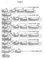
- Fig. 7 is a block diagram showing the details of the information separating circuit in the recording portion of the digital VTR in accordance with the second embodiment.
- data from 0th stage to 5th state are formed, and the following components are added to the circuit structure of the first embodiment shown in Fig. 3.
- a third decoding circuit 25, a third interpolating circuit 26 and a third difference circuit 20 are provided for forming the third stage data.
- a tertiary subsampling circuit 21, a third memory 22, a fourth decoding circuit 31, a fourth interpolating circuit 32, a fourth difference circuit 23 and a fourth coding circuit 24 are provided for the second stage data.
- a quartic subsampling circuit 27, a fourth memory 28, a fifth decoding circuit 36, a fifth interpolating circuit 37, a fifth difference circuit 29 and a fifth coding circuit 30 are provided for forming the first stage data.
- a quintic subsampling circuit 33, a fifth memory 34 and a sixth coding circuit 35 are provided for forming the 0th stage data.
- the first, second and the third coding circuits 14, 10 and 36 are formed by variable length encoders and the fourth, the fifth and the sixth coding circuits 24, 30 and 35 are formed by fixed length encoders.
- the data of the 0th stage to the fifth stage are formed in the same manner as those of the first embodiment shown in Fig. 3, so that the description thereof is not repeated.
- Fig. 8 schematically shows the arrangement of recorded information on the recording tracks on the tape in accordance with the second embodiment.
- the recording tracks TA and TB represent recording tracks simultaneously formed on the tape by one composite head, the recording azimuth being different from each other.
- the 0th stage data are recorded at the center of each recording track. The first stage data are recorded on both sides thereof the second stage data are recorded further outside thereof, the third stage data are recorded further outside, the fourth stage data are recorded further outside and the fifth stage data are recorded further outside thereof.
- Figs. 9 and 10 show relations between the recording track pattern in reproducing information recorded in the above described manner while the tape is running at high speed and the tracks of scanning of the reproduction head.
- Fig. 9 shows reproduction at three times normal speed
- Fig. 10 shows reproduction at five times normal speed.
- Fig. 11 shows a reproduction circuit for processing data reproduced from a head during high speed reproduction in accordance with the second embodiment of the present invention.
- the data of respective stages outputted from the data separating circuit 18 are applied to a data selecting circuits 38.
- the data selecting circuit 38 selects and provides only the effective stage data corresponding to how many times as fast as the normal speed the information is to be reproduced.
- the effective stage data provided from the data selecting circuit 38 are applied to a reduction image data forming circuit 39 which circuit 39 forms digital data to form a reduce image in accordance with the speed of reproduction to apply the same to a D/A converter 40.
- the analog signal provided by the D/A converter 40 is applied to a video signal forming circuit 41, the video signal forming circuit 41 adds a synchronization signal and a blue back signal for the margin around the image plane to the applied analog video signal.
- the video signal formed in this manner is applied to one input of a multiplexing circuit 43.
- mode information, information of the tape remaining time, time code information (information of the past time) and so on which are to be multiplexed over the blue black portion are applied as character pattern signals to the other input portion of the multiplexing circuit 43 from an additional information generating circuit 42. Therefore, multiplex signals indicative of the reduced image plane and the above mentioned additional information are outputted from the multiplexing circuit 43.
- FIG. 12(A) shows an example of a display pattern in a three times normal speed mode provided in this manner
- Fig. 12 (B) shows an example of the display pattern in the five times normal speed mode provided in this manner.
- the size of the reduced image plane becomes smaller as the speed is increased, and various additional information are displayed on the margin on the right side thereof.
- n is a positive integer
- a reproduced image having necessary definition can be formed based on the reproduced video information during high speed reproduction in a digital VTR.
Landscapes
- Engineering & Computer Science (AREA)
- Multimedia (AREA)
- Signal Processing (AREA)
- Signal Processing For Digital Recording And Reproducing (AREA)
- Television Signal Processing For Recording (AREA)
Claims (10)
- Digitaler Videobandrecorder, mit:
einer Einrichtung zum Bereitstellen digitaler Videoinformation (100, 200, 1);
einer Videoinformation-Trenneinrichtung (300) zum Unterteilen der digitalen Videoinformation in Hauptinformation, die das gesamte Bild in Rohform bilden kann, und Unterinformation, die Einzelheiten des Bildes zur Bereitstellung bildet;
einer ersten Videoinformation-Verarbeitungseinrichtung (400) zum Durchführen eines Fehlerkorrektur-Verfahrens an der bereitgestellten Hauptinformation;
einer zweiten Videoinformation-Verarbeitungseinrichtung (500) zum Durchführen eines Fehlerkorrektur-Verfahrens an der bereitgestellten Unterinformation; und
einer Aufzeichnungseinrichtung (600) zum Aufzeichnen von Ausgaben von der ersten und zweiten Videoinformation-Verarbeitungseinrichtung auf einem Magnetband, so daß die Ausgabe von der ersten Videoinformation-Verarbeitungseinrichtung in der Mitte jeder Aufzeichnungspur in einer n-Feldeinheit (wobei n eine positive ganze Zahl ist) aufgezeichnet wird und die Ausgabe von der zweiten Videoinformation-Verarbeitungseinrichtung auf äußeren Abschnitten der Aufzeichnungsspur beiderseits der Mitte aufgezeichnet wird. - Digitaler Videobandrecorder nach Anspruch 1, wobei die Videoinformation-Trenneinrichtung erste bis m-te Unterabtast-Einrichtungen (2, 4, 21, 27, 33) zum Durchführen erster bis m-ter (wobei m eine positive ganze Zahl ist) stufenweiser Unterabtast-Verfahren an der digitalen Videoinformation und
Einrichtungen zur Bildung von Daten erster bis (m + 1)-ter Stufe (14, 10, 6, 24, 30, 35) zum jeweiligen Bilden von Bilddaten m-ter bis nullter Stufe auf der Grundlage der digitalen Videoinformation und von Ausgaben der ersten bis m-ten Unterabtast-Einrichtungen aufweist, und
wobei die Videoinformation-Trenneinrichtung Bilddaten null-ter bis 1-ter Stufe (wobei 1 null oder eine positive ganze Zahl ist) als die Hauptinformation und Bilddaten anderer Stufen als die Unterinformation liefert. - Digitaler Videobandrecorder nach Anspruch 2, wobei die Videoinformation-Trenneinrichtung (300)
eine erste und zweite Unterabtast-Einrichtung (2, 4) und Erst- bis Drittstufen-Datenbildungseinrichtungen (14, 10, 6)
zum jeweiligen Ausbilden von Bilddaten zweiter bis nullter Stufe beinhaltet, und
wobei die Videoinformation-Trenneinrichtung (300) die Bilddaten der nullten Stufe als die Hauptinformation und die Bilddaten der ersten und zweiten Stufe als die Unterinformation bereitstellt. - Digitaler Videobandrecorder nach Anspruch 3, wobei die Drittstufen-Datenbildungseinrichtung eine dritte Codiereinrichtung (6) zum Codieren einer Ausgabe von der zweiten Unterabtast-Einrichtung, um diese als Bilddaten nullter Stufe bereitzustellen, und eine Zweitdaten-Wiederherstellungseinrichtung (7, 8) zum Decodieren der Bilddaten nullter Stufe und Durchführen einer Dateninterpolation zum Wiederherstellen der Daten enthält;
die Zweitstufen-Datenbildungseinrichtung eine zweite Codiereinrichtung (10) zum Codieren der Differenz zwischen einer Ausgabe von der ersten Unterabtast-Einrichtung (2) und der Zweitdaten-Wiederherstellungseinrichtung (7, 8) für deren Bereitstellung als die Erststufen-Bilddaten sowie eine Erstdaten-Wiederherstellungseinrichtung (11, 12) zum Decodieren der Erststufen-Bilddaten und Durchführen einer Dateninterpolation zum Wiederherstellen von Daten enthält;
wobei die Erststufen-Datenbildungseinrichtung eine erste Codiereinrichtung (14) zum Codieren einer Diffferenz zwischen der digitalen Videoinformation und der Ausgabe von der Erstdaten-Wiederherstellungseinrichtung (11, 12) enthält, um diese als die Zweitstufen-Bilddaten bereitzustellen. - Digitaler Videobandrecorder nach Anspruch 2, wobei die Videoinformaticn-Trenneinrichtung
erste bis fünfte Unterabtast-Einrichtungen (2, 4, 21, 27, 33) und
Erst- bis Sechststufen-Datenbildungseinrichtungen (14, 10, 6, 24, 30, 35) zum jeweiligen Ausbilden von Bilddaten fünfter bis nullter Stufe enthält, und
wobei die Videoinformation-Trenneinrichtung die Bilddaten nullter Stufe oder die Bilddaten nullter und erster Stufe als die Hauptinformation und Bilddaten anderer Stufen als die Unterinformation bereitstellt. - Digitaler Videobandrecorder nach Anspruch 5, wobei die Sechststufen-Datenbildungseinrichtung eine sechste Codiereinrichtung (35) zum Codieren einer Ausgabe von der fünften Unterabtast-Einrichtung (33) für deren Bereitstellung als die Bilddaten nullter Stufe und eine Fünftdaten-Wiederherstellungseinrichtung (36, 37) zum Decodieren der Bilddaten nullter Stufe und Durchführen einer Dateninterpolation zur Wiederherstellung der Daten enthält;
die Fünftstufen-Datenbildungseinrichtung eine fünfte Codiereinrichtung (30) zum Codieren der Differenz zwischen einer Ausgabe von der vierten Unterabtasteinrichtung (27) und von der Fünftdaten-Wiederherstellungseinrichtung (36, 37) für deren Bereitstellung als die Bilddaten erster Stufe und eine Viertdaten-Wiederherstellungseinrichtung (31, 32) zum Decodieren der Bilddaten erster Stufe und Durchführen einer Dateninterpolation zur Wiederherstellung der Daten enthält;
die Viertstufen-Datenbildungseinrichtung eine vierte Codiereinrichtung (24) zum Codieren der Differenz zwischen einer Ausgabe von der dritten Unterabtasteinrichtung (21) und von der Viertdaten-Wiederherstellungseinrichtung (31, 32) für deren Bereitstellung als die Bilddaten zweiter Stufe und einer Drittdaten-Wiederherstellungseinrichtung (25, 26) zum Decodieren der Bilddaten zweiter Stufe und Durchführen einer Dateninterpolation zur Wiederherstellung der Daten enthält;
die Drittstufen-Datenbildungseinrichtung eine dritte Codiereinrichtung (6) zum Codieren der Differenz zwischen einer Ausgabe von der zweiten Unterabtasteinrichtung (4) und der Drittdaten-Wiederherstellungseinrichtung (25, 26) für deren Bereitstellung als die Bilddaten dritter Stufe und eine Zweitdaten-Wiederherstellungseinrichtung (7, 8) zum Decodieren der Bilddaten dritter Stufe und Durchführen einer Dateninterpolation zur Wiederherstellung der Daten enthält;
die Zweitstufen-Datenbildungseinrichtung eine zweite Codiereinrichtung (10) zum Codieren der Differenz zwischen der Ausgabe von der ersten Unterabtasteinrichtung (2) und von der Zweitdaten-Wiederherstellungseinrichtung (7, 8) für deren Bereitstellung als die Bilddaten vierter Stufe und eine Erstdaten-Wiederherstellungseinrichtung (11, 12) zum Decodieren der Bilddaten vierter Stufe und Durchführen einer Dateninterpolation zur Wiederherstellung der Daten enthält; und
die Erststufen-Datenbildungseinrichtung eine erste Codiereinrichtung (14) zum Codieren der Differenz zwischen der digitalen Videoinformation und der Ausgabe von der Erstdaten-Wiederherstellungseinrichtung (11, 12) für deren Bereitstellung als die Bilddaten fünfter Stufe enthält. - Digitaler Videobandrecorder nach Anspruch 1, der weiterhin aufweist:
eine Einrichtung (17, 18, 38) zum Wiedergeben von zumindest der Hauptinformation von der Aufzeichnungsspur, während ein Magnetband, auf dem die Ausgaben von der ersten und zweiten Videoinformation-Verarbeitungseinrichtung aufgezeichnet sind, mit hoher Geschwindigkeit betrieben wird; und
einer Einrichtung (19, 39, 40, 41) zum Bilden von Videoinformation, die auf der wiedergegebenen Hauptinformation beruht. - Digitaler Videobandrecorder nach Anspruch 7, wobei die auf der wiedergegebenen Hauptinformation beruhende, wiedergegebene Videoinformation ein Videosignal mit veränderlicher Verdichtungsrate ist, und
der digitale Videobandrecorder weiterhin eine Einrichtung (39) zum Ändern der Verdichtungsrate in Übereinstimmung mit der Menge der wiedergegebenen Hauptinformation aufweist. - Digitaler Videobandrecorder nach Anspruch 8, der weiterhin aufweist:
eine Einrichtung (42) zum Bereitstellen eines Signals, das auf zusätzliche Information hinweist und auf einem Rand, der um ein verringertes Videobild herum gebildet wird, durch das Videosignal angezeigt werden soll; und
eine Einrichtung (43) zum Multiplexen des Videosignals und des Zusatzinformationssignals. - Digitaler Videobandrecorder nach Anspruch 1, wobei die Hauptinformation durch Codierung mit fester Länge und die Unterinformation durch Codierung mit veränderlicher Länge gebildet wird.
Applications Claiming Priority (6)
| Application Number | Priority Date | Filing Date | Title |
|---|---|---|---|
| JP277879/88 | 1988-11-02 | ||
| JP27787988 | 1988-11-02 | ||
| JP331059/88 | 1988-12-28 | ||
| JP33105988 | 1988-12-28 | ||
| JP15198389 | 1989-06-13 | ||
| JP151983/89 | 1989-06-13 |
Publications (3)
| Publication Number | Publication Date |
|---|---|
| EP0367264A2 EP0367264A2 (de) | 1990-05-09 |
| EP0367264A3 EP0367264A3 (de) | 1992-09-02 |
| EP0367264B1 true EP0367264B1 (de) | 1995-07-19 |
Family
ID=27320202
Family Applications (1)
| Application Number | Title | Priority Date | Filing Date |
|---|---|---|---|
| EP89120304A Expired - Lifetime EP0367264B1 (de) | 1988-11-02 | 1989-11-02 | Digitaler Videobandrecorder, geeignet zur Bildwiedergabe mit hoher Geschwindigkeit |
Country Status (3)
| Country | Link |
|---|---|
| US (1) | US5136391A (de) |
| EP (1) | EP0367264B1 (de) |
| DE (1) | DE68923532T2 (de) |
Families Citing this family (106)
| Publication number | Priority date | Publication date | Assignee | Title |
|---|---|---|---|---|
| DE3925663A1 (de) * | 1989-08-03 | 1991-02-07 | Thomson Brandt Gmbh | Digitales signalverarbeitungssystem |
| US5502570A (en) * | 1990-02-13 | 1996-03-26 | Canon Kabushiki Kaisha | Images reproducing method capable of skipping reproduction of collateral information during reproduction in a special mode |
| US5544176A (en) * | 1990-02-13 | 1996-08-06 | Canon Kabushiki Kaisha | Information recording apparatus which eliminates unnecessary data before recording |
| NL9000424A (nl) * | 1990-02-22 | 1991-09-16 | Philips Nv | Overdrachtsysteem voor gedigitaliseerde televisiebeelden. |
| JPH0486183A (ja) * | 1990-07-30 | 1992-03-18 | Matsushita Electric Ind Co Ltd | 映像信号の記録再生装置 |
| JP2848001B2 (ja) * | 1990-10-31 | 1999-01-20 | ソニー株式会社 | ディジタルデータの磁気記録装置 |
| US5416651A (en) * | 1990-10-31 | 1995-05-16 | Sony Corporation | Apparatus for magnetically recording digital data |
| US5844737A (en) * | 1990-11-14 | 1998-12-01 | Canon Kabushiki Kaisha | Reproducing apparatus with different reproduction data for normal and search modes which scans two areas of a split tape recording medium in opposite directions |
| JPH04181884A (ja) * | 1990-11-16 | 1992-06-29 | Sony Corp | 映像信号記録装置 |
| JPH04206072A (ja) * | 1990-11-30 | 1992-07-28 | Sony Corp | 磁気記録再生装置 |
| GB2252001B (en) * | 1991-01-11 | 1995-01-04 | Sony Broadcast & Communication | Storage of video signals |
| GB2251757A (en) * | 1991-01-11 | 1992-07-15 | Sony Broadcast & Communication | Reproduction and storage of video signals |
| US5282049A (en) * | 1991-02-08 | 1994-01-25 | Olympus Optical Co., Ltd. | Moving-picture data digital recording and reproducing apparatuses |
| JP2909239B2 (ja) * | 1991-03-27 | 1999-06-23 | 株式会社東芝 | 高能率符号化記録再生装置 |
| SG65702A1 (en) * | 1991-04-10 | 1999-06-22 | Mitsubishi Electric Corp | Encorder and decorder |
| DE69222801T2 (de) * | 1991-04-18 | 1998-04-02 | Koninkl Philips Electronics Nv | System und Verfahren zur Verbesserung der Suchbetriebsart bei einem Video Recorder |
| US5748832A (en) * | 1991-05-28 | 1998-05-05 | Canon Kabushiki Kaisha | Video signal reproducing system |
| DE69233538T2 (de) * | 1991-09-30 | 2006-06-29 | Kabushiki Kaisha Toshiba, Kawasaki | Gerät zur Verarbeitung von bandkomprimierten Signalen für Aufnahme/Wiedergabe |
| US5845041A (en) * | 1991-11-12 | 1998-12-01 | Mitsubishi Denki Kabushiki Kaisha | Video signal recording and reproducing apparatus with high efficiency encoding |
| JPH05260438A (ja) * | 1991-11-12 | 1993-10-08 | Samsung Electron Co Ltd | 可変速再生のためのディジタル磁気テープ記録再生方法 |
| JP3161614B2 (ja) * | 1991-11-30 | 2001-04-25 | ソニー株式会社 | 動画像復号化装置 |
| US5377014A (en) * | 1992-01-06 | 1994-12-27 | At&T Corp. | Apparatus and method for displaying recorded compressed digital high definition video information |
| DE69229945T2 (de) * | 1992-01-13 | 2000-05-18 | Koninklijke Philips Electronics N.V., Eindhoven | Verfahren und System zum Senden und Empfangen von digitalkodierten Videobildern |
| EP0551694A1 (de) * | 1992-01-15 | 1993-07-21 | Matsushita Electric Industrial Co., Ltd. | Verfahren zum Aufzeichnen eines digitalen Videosignals |
| KR100206262B1 (ko) * | 1992-02-29 | 1999-07-01 | 윤종용 | 디지탈 브이티알의 재생화면 탐색제어장치 |
| KR0150954B1 (ko) * | 1992-03-14 | 1998-10-15 | 강진구 | 디지털 기록재생 장치의 에러 정정 부호화/복호화 방법 및 그에 적합한 장치 |
| FR2688970A1 (fr) * | 1992-03-20 | 1993-09-24 | Thomson Broadcast | Dispositif de lecture et/ou d'ecriture de support magnetique et magnetoscope contenant de tels dispositifs. |
| DE69323338T2 (de) * | 1992-03-24 | 1999-06-10 | Kabushiki Kaisha Toshiba, Kawasaki, Kanagawa | Vorrichtung zum Aufzeichnen/Wiedergeben von Kodes mit variablen Längen für einen Videorekorder |
| US5734784A (en) * | 1992-03-25 | 1998-03-31 | Kabushiki Kaisha Toshiba | High data rate system and method for video recording and playback |
| US5339108A (en) * | 1992-04-09 | 1994-08-16 | Ampex Corporation | Ordering and formatting coded image data and reconstructing partial images from the data |
| US5526135A (en) * | 1992-05-11 | 1996-06-11 | Sony Corporation | Video signal recording and/or reproducing apparatus operable in normal and differential speed playback modes |
| US5675696A (en) * | 1992-07-14 | 1997-10-07 | Mitsubishi Denki Kabsuhiki Kaisha | Digital video signal recording and reproducing apparatus |
| JP3290512B2 (ja) * | 1992-08-24 | 2002-06-10 | 三菱電機株式会社 | 磁気記録再生装置 |
| US5583650A (en) * | 1992-09-01 | 1996-12-10 | Hitachi America, Ltd. | Digital recording and playback device error correction methods and apparatus for use with trick play data |
| US5623344A (en) * | 1992-09-01 | 1997-04-22 | Hitachi America, Ltd. | Digital video recording device with trick play capability |
| GB2270811B (en) * | 1992-09-17 | 1996-02-07 | Sony Broadcast & Communication | Video data compression |
| DE4234723A1 (de) * | 1992-10-15 | 1994-04-21 | Philips Patentverwaltung | Anordnung für Gerät zur Aufzeichnung und/oder Wiedergabe digitaler Videodaten |
| JPH06150568A (ja) * | 1992-11-06 | 1994-05-31 | Sony Corp | データ記録装置 |
| US5561608A (en) * | 1992-11-18 | 1996-10-01 | Kabushiki Kaisha Toshiba | Multisystem adaptable type signal processing and recording/reproducing apparatus |
| JP3093494B2 (ja) * | 1992-11-18 | 2000-10-03 | 株式会社東芝 | 多様性信号処理装置 |
| KR0176474B1 (ko) * | 1992-12-01 | 1999-04-15 | 김광호 | 고속화상 재생에 적합한 디지탈 비디오 테이프레코더용 데이타 코딩기술 |
| US5398143A (en) * | 1992-12-01 | 1995-03-14 | Samsung Electronics Co., Ltd. | Data placement on tape for a digital video tape recorder suitable for high speed picture playback |
| EP0600495B1 (de) * | 1992-12-04 | 2003-03-12 | Matsushita Electric Industrial Co., Ltd. | Vorrichtung zum Aufnehmen und zur Wiedergabe eines digitalen Videosignals |
| JP3240017B2 (ja) * | 1993-01-11 | 2001-12-17 | ソニー株式会社 | Mpeg信号記録方法およびmpeg信号再生方法 |
| US5933567A (en) * | 1993-01-13 | 1999-08-03 | Hitachi America, Ltd. | Method and apparatus for controlling the position of the heads of a digital video tape recorder during trick play operation and for recording digital data on a tape |
| JP3261844B2 (ja) * | 1993-01-13 | 2002-03-04 | 株式会社日立製作所 | デジタルビデオ記録装置及び記録方法 |
| DE69423794T2 (de) * | 1993-01-13 | 2000-12-28 | Hitachi, Ltd. | Vorrichtung zur Aufzeichnung von digitalen Videosignalen mit Wiedergabe mit variabler Geschwindigkeit |
| US5717816A (en) * | 1993-01-13 | 1998-02-10 | Hitachi America Ltd. | Method and apparatus for the selection of data for use in VTR trick playback operation in a system using intra-coded video frames |
| US5673358A (en) * | 1993-01-13 | 1997-09-30 | Hitachi America, Ltd. | Method for generating a reduced rate digital bitstream by selecting data as a function of the position within an image to which the data corresponds |
| US5576902A (en) * | 1993-01-13 | 1996-11-19 | Hitachi America, Ltd. | Method and apparatus directed to processing trick play video data to compensate for intentionally omitted data |
| US5726711A (en) * | 1993-01-13 | 1998-03-10 | Hitachi America, Ltd. | Intra-coded video frame data processing methods and apparatus |
| US5444575A (en) * | 1994-01-21 | 1995-08-22 | Hitachi America, Ltd. | Method for recording digital data using a set of heads including a pair of co-located heads to record data at a rate lower than the full recording rate possible using the set of heads |
| US5778143A (en) * | 1993-01-13 | 1998-07-07 | Hitachi America, Ltd. | Method and apparatus for the selection of data for use in VTR trick playback operation in a system using progressive picture refresh |
| US5805762A (en) * | 1993-01-13 | 1998-09-08 | Hitachi America, Ltd. | Video recording device compatible transmitter |
| US5614952A (en) * | 1994-10-11 | 1997-03-25 | Hitachi America, Ltd. | Digital video decoder for decoding digital high definition and/or digital standard definition television signals |
| US5377051A (en) * | 1993-01-13 | 1994-12-27 | Hitachi America, Ltd. | Digital video recorder compatible receiver with trick play image enhancement |
| US5887115A (en) * | 1993-01-13 | 1999-03-23 | Hitachi America, Ltd. | Method and apparatus for implementing a video tape recorder for recording digital video signals having either a fixed or variable data transmission rate |
| US5786858A (en) * | 1993-01-19 | 1998-07-28 | Sony Corporation | Method of encoding image signal, apparatus for encoding image signal, method of decoding image signal, apparatus for decoding image signal, and image signal recording medium |
| GB9301093D0 (en) * | 1993-01-20 | 1993-03-10 | Rca Thomson Licensing Corp | Digital video tape recorder for digital hdtv |
| KR100269748B1 (ko) * | 1993-01-30 | 2000-10-16 | 윤종용 | 디지탈 vtr의 영상데이타처리방법 및 그 장치 |
| US5448369A (en) * | 1993-02-13 | 1995-09-05 | Goldstar Co., Ltd. | Apparatus for a high definition VCR which selects a video signal characteristic to be transmitted depending on characteristics of the tap and channel |
| US5477397A (en) * | 1993-02-23 | 1995-12-19 | Matsushita Electric Corporation Of America | Digital high definition television receiver with features that facilitate trick-play modes on a digital VCR |
| CA2115976C (en) * | 1993-02-23 | 2002-08-06 | Saiprasad V. Naimpally | Digital high definition television video recorder with trick-play features |
| US5532831A (en) * | 1993-03-19 | 1996-07-02 | Goldstar Company, Ltd. | Recording apparatus and method for a high definition video cassette recorder |
| US5587806A (en) * | 1993-03-26 | 1996-12-24 | Matsushita Electric Industrial Co., Ltd. | Apparatus for separately recording input coded video signal and important data generated therefrom |
| US5563661A (en) * | 1993-04-05 | 1996-10-08 | Canon Kabushiki Kaisha | Image processing apparatus |
| DE69425788T2 (de) * | 1993-05-27 | 2001-01-04 | Matsushita Electric Industrial Co., Ltd. | Digitaler Videorekorder für Videosignale mit hoher Auflösung mit hoch aufgelöster Anzeige in speziellen Wiedergabebetreibsarten |
| JPH0799646A (ja) * | 1993-05-31 | 1995-04-11 | Sony Corp | ディジタル画像信号の階層符号化および復号装置 |
| US5596421A (en) * | 1993-06-03 | 1997-01-21 | Matsushita Electric Industrial Co., Ltd. | Optical disk recorder for video signals and an optical disk for use therein |
| US5812735A (en) * | 1993-07-09 | 1998-09-22 | Sony Corporaiton | Picture signal decoding method and picture signal decoding apparatus |
| BE1007330A3 (nl) * | 1993-07-16 | 1995-05-16 | Philips Electronics Nv | Inrichting voor het overdragen van een digitaal beeldsignaal. |
| DE69418942T2 (de) * | 1993-08-13 | 1999-12-09 | Nec Corp., Tokio/Tokyo | Gerät zur Komprimierung und Wiedergabe von Video/Audio-Daten |
| US5486929A (en) * | 1993-09-03 | 1996-01-23 | Apple Computer, Inc. | Time division multiplexed video recording and playback system |
| BE1007658A3 (nl) * | 1993-10-14 | 1995-09-05 | Philips Electronics Nv | Werkwijze voor het in gecodeerde vorm opslaan van beeldinformatie van bewegende beelden, een diagnostisch systeem waarin de werkwijze wordt toegepast, alsmede een beeldcoderings- en optekeneenheid voor toepassing in een dergelijk systeem. |
| EP0649254B1 (de) * | 1993-10-14 | 1999-03-17 | Koninklijke Philips Electronics N.V. | Verfahren zur Speicherung von kodierten Bilddaten |
| JPH07154742A (ja) * | 1993-11-25 | 1995-06-16 | Matsushita Electric Ind Co Ltd | 記録装置および再生装置 |
| US6434319B1 (en) | 1994-01-19 | 2002-08-13 | Thomson Licensing S.A. | Digital video tape recorder for digital HDTV |
| TW374159B (en) * | 1994-01-24 | 1999-11-11 | Victor Company Of Japan | Video signal reproducing method and apparatus |
| WO1995021504A1 (en) * | 1994-02-02 | 1995-08-10 | Sony Corporation | Recording device and reproducing device |
| EP0673157A3 (de) * | 1994-03-14 | 1995-11-22 | Matsushita Electric Industrial Co Ltd | Gerät zur Aufzeichnung und Wiedergabe. |
| DE69514177T2 (de) * | 1994-03-18 | 2000-08-31 | Koninklijke Philips Electronics N.V., Eindhoven | System für audiovisuelle vorführung |
| CN1115149A (zh) * | 1994-04-01 | 1996-01-17 | 株式会社东芝 | 数字图象信号的记录重放方法及设备 |
| JP3385109B2 (ja) * | 1994-04-12 | 2003-03-10 | 三菱電機株式会社 | ディジタルvtr |
| JP3322998B2 (ja) * | 1994-04-12 | 2002-09-09 | 三菱電機株式会社 | ディジタルvtr |
| US6977964B1 (en) * | 1994-04-12 | 2005-12-20 | Mitsubishi Denki Kabushiki Kaisha | Digital VTR for recording and replaying data depending on replay modes |
| JP3089160B2 (ja) * | 1994-05-20 | 2000-09-18 | シャープ株式会社 | ディジタル記録再生装置 |
| EP0685966B1 (de) * | 1994-05-24 | 2000-12-06 | Victor Company Of Japan, Ltd. | Anlage zum Aufnehmen und Wiedergeben von bewegten Bildern |
| KR970010533B1 (en) * | 1994-06-30 | 1997-06-26 | Samsung Electronics Co Ltd | Recording and reproducing method of dvcr for trick play |
| JP3330459B2 (ja) * | 1994-07-04 | 2002-09-30 | 三菱電機株式会社 | 磁気記録再生装置 |
| JP3172635B2 (ja) * | 1994-07-14 | 2001-06-04 | シャープ株式会社 | ディジタル記録再生装置 |
| US5592299A (en) * | 1994-09-26 | 1997-01-07 | Hitachi America, Ltd. | Method and apparatus for reducing the amount of data required to represent a video frame |
| CN1076505C (zh) * | 1994-10-06 | 2001-12-19 | 财团法人工业技术研究院 | 用旋转式磁头记录或读取多种速率信息的方法与装置 |
| GB9421206D0 (en) * | 1994-10-20 | 1994-12-07 | Thomson Consumer Electronics | Digital VCR MPEG- trick play processing |
| US6122433A (en) * | 1994-10-20 | 2000-09-19 | Thomson Licensing S.A. | HDTV trick play stream derivation for VCR |
| US5615018A (en) * | 1994-11-22 | 1997-03-25 | Industrial Technology Research Instiutute | Apparatus and a method for variable speed searching of recorded pictures |
| US5832170A (en) * | 1994-12-16 | 1998-11-03 | Sony Corporation | Apparatus and method for storing and reproducing high-resolution video images |
| JP3226444B2 (ja) * | 1995-01-25 | 2001-11-05 | 三菱電機株式会社 | ディジタル信号記録装置及び再生装置 |
| DE69617774T2 (de) * | 1995-03-07 | 2002-08-08 | Matsushita Electric Industrial Co., Ltd. | Vorrichtung zur Aufzeichnung und Wiedergabe von Daten |
| US5621660A (en) * | 1995-04-18 | 1997-04-15 | Sun Microsystems, Inc. | Software-based encoder for a software-implemented end-to-end scalable video delivery system |
| JP3561083B2 (ja) * | 1996-05-24 | 2004-09-02 | 株式会社東芝 | データ配置制御方法及びビデオサーバ装置 |
| US6122321A (en) * | 1998-05-12 | 2000-09-19 | Hitachi America, Ltd. | Methods and apparatus for reducing the complexity of inverse quantization operations |
| US6148032A (en) * | 1998-05-12 | 2000-11-14 | Hitachi America, Ltd. | Methods and apparatus for reducing the cost of video decoders |
| US6385248B1 (en) | 1998-05-12 | 2002-05-07 | Hitachi America Ltd. | Methods and apparatus for processing luminance and chrominance image data |
| US6687068B2 (en) * | 2001-03-27 | 2004-02-03 | International Business Machines Corporation | Data reproduction apparatus and method |
| JP2003067224A (ja) * | 2001-08-23 | 2003-03-07 | Sanyo Electric Co Ltd | 情報処理装置 |
| CN104094603B (zh) * | 2011-12-28 | 2018-06-08 | 英特尔公司 | 用于在视频编码系统中进行集成元数据插入的系统和方法 |
Family Cites Families (12)
| Publication number | Priority date | Publication date | Assignee | Title |
|---|---|---|---|---|
| US4063290A (en) * | 1976-03-24 | 1977-12-13 | Eastman Kodak Company | Video recording apparatus |
| GB2098021B (en) * | 1981-05-06 | 1985-06-19 | Sony Corp | Digital television apparatuses |
| US4742558A (en) * | 1984-02-14 | 1988-05-03 | Nippon Telegraph & Telephone Public Corporation | Image information retrieval/display apparatus |
| JPS6139783A (ja) * | 1984-07-31 | 1986-02-25 | Matsushita Electric Ind Co Ltd | 記録再生装置 |
| GB2164480B (en) * | 1984-09-18 | 1988-01-13 | Sony Corp | Reproducing digital audio signals |
| US4757391A (en) * | 1985-02-28 | 1988-07-12 | Victor Company Of Japan, Ltd. | Helical scan type magnetic recording and reproducing apparatus recording multiple signals on multiple axially displaced tape tracks |
| JPS62234478A (ja) * | 1986-04-04 | 1987-10-14 | Matsushita Electric Ind Co Ltd | 映像信号の記録再生装置 |
| US4914527A (en) * | 1986-04-09 | 1990-04-03 | Sony Corporation | Recording and reproducing digital video and audio signals together with a time code signal which is within user control words of the audio data |
| US4811116A (en) * | 1986-10-10 | 1989-03-07 | Eastman Kodak Company | Video recorder using extended tape tracks to record compressed chrominance |
| US4789894A (en) * | 1987-03-16 | 1988-12-06 | Eastman Kodak Company | Motion analyzer with interleaved image reproduction |
| US4899232A (en) * | 1987-04-07 | 1990-02-06 | Sony Corporation | Apparatus for recording and/or reproducing digital data information |
| JP2606308B2 (ja) * | 1988-07-28 | 1997-04-30 | ソニー株式会社 | デジタルvtrのダイナミックトラッキング方法 |
-
1989
- 1989-10-30 US US07/429,081 patent/US5136391A/en not_active Expired - Fee Related
- 1989-11-02 DE DE68923532T patent/DE68923532T2/de not_active Expired - Fee Related
- 1989-11-02 EP EP89120304A patent/EP0367264B1/de not_active Expired - Lifetime
Also Published As
| Publication number | Publication date |
|---|---|
| EP0367264A3 (de) | 1992-09-02 |
| EP0367264A2 (de) | 1990-05-09 |
| DE68923532D1 (de) | 1995-08-24 |
| DE68923532T2 (de) | 1996-03-21 |
| US5136391A (en) | 1992-08-04 |
Similar Documents
| Publication | Publication Date | Title |
|---|---|---|
| US5136391A (en) | Digital video tape recorder capable of accurate image reproduction during high speed tape motion | |
| US5589993A (en) | Digital high definition television video recorder with trick-play features | |
| EP1043893B1 (de) | Gerät zur Bildverarbeitung | |
| US5477397A (en) | Digital high definition television receiver with features that facilitate trick-play modes on a digital VCR | |
| US5493456A (en) | Method and apparatus for increasing the recording time of a digital video tape recorder | |
| US5473479A (en) | Digital recording and/or reproduction apparatus of video signal rearranging components within a fixed length block | |
| EP0552049B1 (de) | Vorrichtung zur digitalen Aufzeichung und/oder Wiedergabe eines Videosignals | |
| EP0554086B1 (de) | Vorrichtung zum Aufzeichnen von Videoinformation | |
| EP0642274B1 (de) | Gerät zur Aufzeichnung und Wiedergabe eines Videosignals | |
| US4963992A (en) | Apparatus for recording/reproducing digital video signals in both a standard mode and a long playing mode | |
| JP3133878B2 (ja) | 高速画像再生に適したデジタルビデオテープレコーダのテープ上のデータ配置技術 | |
| EP0534620B1 (de) | Verfahren und Vorrichtung zum Erzeugen eines Kopiersignals mit hoher Geschwindigkeit | |
| US5510904A (en) | Video data compressor minimizing propagation of error | |
| EP0772366B1 (de) | Digitales Aufzeichnungs-/Wiedergabegerät | |
| EP0523708B1 (de) | Verfahren und Vorrichtung zum Aufzeichnen von digitalen Videosignalen | |
| US6219157B1 (en) | Image coding apparatus | |
| US6233281B1 (en) | Video signal processing apparatus, and video signal processing method | |
| JPH0530470A (ja) | デイジタルビデオ信号の記録および/または再生方法 | |
| JPH06276548A (ja) | マルチ入力画像記録再生装置 | |
| JPH07298195A (ja) | 画像情報圧縮伸長装置 | |
| JPH07147686A (ja) | テレビジョン信号のディジタル録画装置 | |
| HK1002216B (en) | Digital recording and/or reproduction apparatus of video signal | |
| JPH03128587A (ja) | ディジタルvtr | |
| JPH05167982A (ja) | デジタルビデオカセットレコーダ |
Legal Events
| Date | Code | Title | Description |
|---|---|---|---|
| PUAI | Public reference made under article 153(3) epc to a published international application that has entered the european phase |
Free format text: ORIGINAL CODE: 0009012 |
|
| AK | Designated contracting states |
Kind code of ref document: A2 Designated state(s): DE FR GB |
|
| 17P | Request for examination filed |
Effective date: 19901228 |
|
| PUAL | Search report despatched |
Free format text: ORIGINAL CODE: 0009013 |
|
| AK | Designated contracting states |
Kind code of ref document: A3 Designated state(s): DE FR GB |
|
| 17Q | First examination report despatched |
Effective date: 19940517 |
|
| GRAA | (expected) grant |
Free format text: ORIGINAL CODE: 0009210 |
|
| AK | Designated contracting states |
Kind code of ref document: B1 Designated state(s): DE FR GB |
|
| PG25 | Lapsed in a contracting state [announced via postgrant information from national office to epo] |
Ref country code: FR Effective date: 19950719 |
|
| REF | Corresponds to: |
Ref document number: 68923532 Country of ref document: DE Date of ref document: 19950824 |
|
| EN | Fr: translation not filed | ||
| PLBE | No opposition filed within time limit |
Free format text: ORIGINAL CODE: 0009261 |
|
| STAA | Information on the status of an ep patent application or granted ep patent |
Free format text: STATUS: NO OPPOSITION FILED WITHIN TIME LIMIT |
|
| 26N | No opposition filed | ||
| REG | Reference to a national code |
Ref country code: GB Ref legal event code: IF02 |
|
| PGFP | Annual fee paid to national office [announced via postgrant information from national office to epo] |
Ref country code: GB Payment date: 20021030 Year of fee payment: 14 |
|
| PGFP | Annual fee paid to national office [announced via postgrant information from national office to epo] |
Ref country code: DE Payment date: 20021107 Year of fee payment: 14 |
|
| PG25 | Lapsed in a contracting state [announced via postgrant information from national office to epo] |
Ref country code: GB Free format text: LAPSE BECAUSE OF NON-PAYMENT OF DUE FEES Effective date: 20031102 |
|
| PG25 | Lapsed in a contracting state [announced via postgrant information from national office to epo] |
Ref country code: DE Free format text: LAPSE BECAUSE OF NON-PAYMENT OF DUE FEES Effective date: 20040602 |
|
| GBPC | Gb: european patent ceased through non-payment of renewal fee |
Effective date: 20031102 |