EP0367500B1 - Warmwalzen von Metallband - Google Patents
Warmwalzen von Metallband Download PDFInfo
- Publication number
- EP0367500B1 EP0367500B1 EP89311055A EP89311055A EP0367500B1 EP 0367500 B1 EP0367500 B1 EP 0367500B1 EP 89311055 A EP89311055 A EP 89311055A EP 89311055 A EP89311055 A EP 89311055A EP 0367500 B1 EP0367500 B1 EP 0367500B1
- Authority
- EP
- European Patent Office
- Prior art keywords
- strip
- rolls
- last stand
- tension
- rolling
- Prior art date
- Legal status (The legal status is an assumption and is not a legal conclusion. Google has not performed a legal analysis and makes no representation as to the accuracy of the status listed.)
- Expired
Links
- 239000002184 metal Substances 0.000 title claims description 11
- 238000005098 hot rolling Methods 0.000 title claims description 3
- 238000005096 rolling process Methods 0.000 claims description 21
- 238000000034 method Methods 0.000 claims description 8
- 230000002093 peripheral effect Effects 0.000 claims description 4
- 238000005452 bending Methods 0.000 claims description 2
- 238000001816 cooling Methods 0.000 claims description 2
- 239000002826 coolant Substances 0.000 description 1
- 238000001514 detection method Methods 0.000 description 1
- 239000007788 liquid Substances 0.000 description 1
- 238000005259 measurement Methods 0.000 description 1
- 230000003287 optical effect Effects 0.000 description 1
- 239000007921 spray Substances 0.000 description 1
- 238000005507 spraying Methods 0.000 description 1
Images
Classifications
-
- B—PERFORMING OPERATIONS; TRANSPORTING
- B21—MECHANICAL METAL-WORKING WITHOUT ESSENTIALLY REMOVING MATERIAL; PUNCHING METAL
- B21B—ROLLING OF METAL
- B21B37/00—Control devices or methods specially adapted for metal-rolling mills or the work produced thereby
- B21B37/28—Control of flatness or profile during rolling of strip, sheets or plates
-
- B—PERFORMING OPERATIONS; TRANSPORTING
- B21—MECHANICAL METAL-WORKING WITHOUT ESSENTIALLY REMOVING MATERIAL; PUNCHING METAL
- B21B—ROLLING OF METAL
- B21B37/00—Control devices or methods specially adapted for metal-rolling mills or the work produced thereby
- B21B37/72—Rear end control; Front end control
-
- B—PERFORMING OPERATIONS; TRANSPORTING
- B21—MECHANICAL METAL-WORKING WITHOUT ESSENTIALLY REMOVING MATERIAL; PUNCHING METAL
- B21B—ROLLING OF METAL
- B21B38/00—Methods or devices for measuring, detecting or monitoring specially adapted for metal-rolling mills, e.g. position detection, inspection of the product
- B21B38/02—Methods or devices for measuring, detecting or monitoring specially adapted for metal-rolling mills, e.g. position detection, inspection of the product for measuring flatness or profile of strips
-
- B—PERFORMING OPERATIONS; TRANSPORTING
- B21—MECHANICAL METAL-WORKING WITHOUT ESSENTIALLY REMOVING MATERIAL; PUNCHING METAL
- B21B—ROLLING OF METAL
- B21B2263/00—Shape of product
- B21B2263/04—Flatness
Definitions
- This invention relates to the rolling of hot metal strip. It is well known to control the shape of metal strip issuing from the last stand of a rolling mill by first detecting variations in tension at regions spaced apart across its width and then controlling one or more parameters of one or more of the mill stands in order to reduce the variation in tension. The variation in tension in the strip at regions across its width indicates the shape of the strip.
- a well known device for detecting strip tension at regions across the width of the strip is sold under the Trade Mark VIDIMON by Davy McKee (Poole) Limited, Wallisdown Road, Poole, Dorset BH12 5AG, England.
- This device comprises a plurality of cylindrical rollers arranged end-to-end and rotatable about a common axis. In use, the device is positioned with the common axis substantially at right angles to the direction of movement of the strip and is urged towards the strip so that part of the periphery of each roller is in contact with a separate longitudinally extending part of the metal strip.
- Each roller has a transducer associated with it for detecting the pressure applied to the roller by the part of the strip which engages it. This is a measure of the tension in that part of the strip.
- An object of the present invention is to provide a method of rolling metal strip in which this difficulty is overcome.
- the leading end of the strip issuing from the last stand of a multi-stand hot rolling mill is passed along a run-out table and is brought into engagement with means which apply longitudinal tension to the portion of the strip between said means and the last stand of the rolling mill; and, until the longitudinal tension is applied to the strip, a non-contact type of strip shape detector is employed adjacent to, and downstream of, the last stand to detect variations in shape across the width of the metal strip and to produce signals representative of said variations; and, when longitudinal tension is applied to the strip, a contact-type of strip tension detector is employed adjacent to, and downstream of, the last stand to detect variations in tension across the width of the strip and to produce signals representative of said variations, said signals being employed, in turn, to adjust the rolling parameters of one or more stands of the rolling mill in the sense to reduce shape variations across the width of the strip substantially to zero.
- Longitudinal tension may be applied to the strip by passing the strip into a gap between a pair of pinch rolls, closing the rolls on to the strip and rotating at least one of the rolls with a greater peripheral speed than the linear speed of the strip issuing from the last stand.
- the longitudinal tension may be applied by engaging the leading end of the strip with a rotary coiler and rotating the coiler at a peripheral speed which coils the strip on to the coiler and also applies longitudinal tension to the strip.
- steps can be taken to correct the shape of the leading end of the strip, if necessary, before the strip has longitudinal tension exerted on it.
- the strip when the strip is not under tension, it can exhibit bad shape, such as wavy edges, which can be detected by the non-contact shapemeter.
- these waves may disappear and inherent bad shape, which would only re-appear under zero tension conditions, cannot be deduced by the non-contact shapemeter and can only be deduced from measurements of tension variation obtained by the contact-type shapemeter.
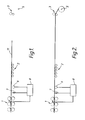
- a multi-stand hot strip rolling mill is indicated generally by reference numeral 1. Downstream of the last stand there is a run-out table 2 leading to a deflector roll unit 3 and a down coiler 5. Also positioned downstream of the last stand of the mill, but close thereto, are a non contact shapemeter 7 and a contact-type tension measuring device 9.
- the shapemeter 7 may be of the type known as a "Lasershape" and sold by SPIE-TRINDEL of 1, rue de la Champagnerie, 57270 Uckange, France. This device employs laser beams and optical triangulation devices to measure, without contact, the vertical location of a plurality of points across the width of the strip with respect to a reference plane.
- the device 9 may be a VIDIMON-type shapemeter.
- the leading end of a metal strip issuing from the rolling mill is shown passing down the run-out table towards the coiler 5. At this time there is no longitudinal tension in the strip.
- the shapemeter 7 is employed to detect variations in shape across the width of the strip and the signals from the shapemeter are supplied to a control circuit indicated generally by reference 8.
- the signals from the shapemeter are used to determine the shape variation of the strip 11 and signals are supplied from the control circuit 8 to adjust the roll parameter of one or more of the stands of the rolling mill 1 in the sense to reduce the shape variations substantially to zero.
- the amount of strip which is rolled with "bad shape" is reduced.
- the shapemeter 7 is no longer employed to determine the shape of the strip and the tension measuring device 9 is brought into contact with the moving strip to detect variations in tension across the width of the strip. This is the situation shown in Figure 2. Signals from the device 9 are supplied to the control circuit 8 instead of signals from the shapemeter 7 and, again, the control ciruit compares the tension variation across the width of the strip and supplies signals to control the settings of one or more stands in the mill in the sense to reduce the tension variation across the width of the strip substantially to zero and, hence, improve the shape of the strip.
- one course of action which can be undertaken is to incline one roll of the pair of work rolls of the last stand of the mill in the vertical plane with respect to the other work roll so that the gap between the two rolls is tapered along its length.
- the shape of the gap between the two work rolls of the last stand can be adjusted by applying bending forces to one or both of the rolls.
- An alternative arrangement for adjusting the shape of the gap is to apply non-uniform cooling along the length of one or both of the work rolls of the last stand. Liquid coolant is usually applied by sprays and, by non-uniform spraying on to the rolls, non-uniform expansion of the rolls takes place and the shape of the gap between the rolls is altered. Any one or any combination of these alternative arrangements may be employed.
Landscapes
- Engineering & Computer Science (AREA)
- Mechanical Engineering (AREA)
- Metal Rolling (AREA)
- Control Of Metal Rolling (AREA)
Claims (6)
- Verfahren zum Walzen von warmem Metallband (11), nach dem das führende Ende des aus dem letzten Walzgerüst eines mehrgerüstigen Warmwalzwerkes (1) heraustretenden Bandes (11) entlang eines Auslauftisches (2) läuft und mit Mitteln (3, 5) in Eingriff gebracht wird, die längsgerichtete Spannung auf den Abschnitt des Bandes (11) zwischen besagten Mitteln (3, 5) und dem letzten Gerüst der Walzstraße (1) aufbringen; und, wenn längsgerichtete Spannung auf das Band (11) aufgebracht wird, ein Berührungs-Bandspannungsdetektor (9) benachbart zu und stromabwärts von dem letzten Gerüst verwendet wird, um Spannungsabweichungen über der Breite des Bandes (11) aufzunehmen und den Spannungsabweichungen entsprechende Signale zu erzeugen, wobei die Signale wiederum verwendet werden, um die Walzparameter von einem oder mehrerer Gerüste der Walzstraße (1) einzustellen, um die Formabweichungen über der Breite des Bandes (11) auf im wesentlichen Null zu reduzieren, dadurch gekennzeichnet, daß, bevor die längsgerichtete Spannung auf das Band (11) aufgebracht wird, ein berührungsloser Bandformdetektor (7) benachbart zu und stromabwärts von dem letzten Gerüst verwendet wird, um Formabweichungen über der Breite des metallischen Bandes (11) aufzunehmen und um den Abweichungen entsprechende Signale zu erzeugen; wobei die Signale verwendet werden, um die Walzparameter von einem oder mehrerer Gerüste der Walzstraße (1) in dem Sinne einzustellen, um die Formabweichungen über der Breite des Bandes (11) auf im wesentlichen Null zu reduzieren.
- Verfahren nach Anspruch 1, dadurch gekennzeichnet, daß längsgerichtete Spannung aufgebracht wird durch Überführen des Bandes in einen Spalt aus Klemmwalzen, durch Schließen der Walzen auf das Band und Rotieren von mindestens einer der Walzen mit einer größeren Umfangsgeschwindigkeit als die Lineargeschwindigkeit von dem aus dem letzten Gerüst austretenden Band auf das Band.
- Verfahren nach Anspruch 1, dadurch gekennzeichnet, daß längsgerichtete Spannung auf das Band aufgebracht wird durch In-Eingriff-bringen des führenden Endes des Bandes mit einer drehenden Aufwickelspule und Drehen der Aufwickelspule mit einer Umfangsgeschwindigkeit, die das Band auf die Spule wickelt.
- Verfahren nach einem der vorherigen Ansprüche, dadurch gekennzeichnet, daß der Walzparameter von dem letzten Gerüst einstellbar ist.
- Verfahren nach Anspruch 4, dadurch gekennzeichnet, daß der Walzparameter der Querschnitt des Walzspaltes zwischen den Walzen des letzten Gerüstes ist.
- Verfahren nach Anspruch 5, dadurch gekennzeichnet, daß der Querschnitt des Walzspaltes durch Anheben einer Walze relativ zu der anderen und/oder durch Biegen von einer oder beider walzen, und/oder durch ungleichmäßiges Kühlen der Walzen eingestellt wird.
Applications Claiming Priority (2)
| Application Number | Priority Date | Filing Date | Title |
|---|---|---|---|
| GB8825714 | 1988-11-03 | ||
| GB888825714A GB8825714D0 (en) | 1988-11-03 | 1988-11-03 | Hot rolling of metal strip |
Publications (3)
| Publication Number | Publication Date |
|---|---|
| EP0367500A2 EP0367500A2 (de) | 1990-05-09 |
| EP0367500A3 EP0367500A3 (en) | 1990-10-31 |
| EP0367500B1 true EP0367500B1 (de) | 1992-12-02 |
Family
ID=10646232
Family Applications (1)
| Application Number | Title | Priority Date | Filing Date |
|---|---|---|---|
| EP89311055A Expired EP0367500B1 (de) | 1988-11-03 | 1989-10-26 | Warmwalzen von Metallband |
Country Status (5)
| Country | Link |
|---|---|
| US (1) | US5018377A (de) |
| EP (1) | EP0367500B1 (de) |
| JP (1) | JPH02175008A (de) |
| DE (1) | DE68903738T2 (de) |
| GB (1) | GB8825714D0 (de) |
Families Citing this family (5)
| Publication number | Priority date | Publication date | Assignee | Title |
|---|---|---|---|---|
| WO1995007776A1 (fr) * | 1993-09-14 | 1995-03-23 | Nippon Steel Corporation | Procede de controle du mouvement de serpentement et ligne de production appliquant ce procede dans une installation de laminage tandem |
| DE19511801A1 (de) * | 1995-03-30 | 1996-10-02 | Schloemann Siemag Ag | Verfahren und Vorrichtung zur Dickenvorsteuerung beim Folienwalzen |
| DE19919801A1 (de) * | 1999-04-30 | 2000-11-02 | Josef Froehling Gmbh Walzwerks | Verfahren zur Messung der Bandzugverteilung bei Walzprozessen |
| EP2258492A1 (de) * | 2009-06-02 | 2010-12-08 | Siemens Aktiengesellschaft | Verfahren zur Herstellung eines Walzguts mittels einer Walzstraße, Steuer- und/oder Regeleinrichtung für eine Walzstraße, Walzanlage zur Herstellung von gewalztem Walzgut, Maschinenlesbarer Programmcode und Speichermedium |
| KR20260021717A (ko) * | 2023-06-29 | 2026-02-13 | 노벨리스 인크. | 광 센서들을 이용한 재료 헤드 평탄도 제어 |
Family Cites Families (10)
| Publication number | Priority date | Publication date | Assignee | Title |
|---|---|---|---|---|
| DE2115344C3 (de) * | 1971-03-30 | 1978-04-27 | Schloemann-Siemag Ag, 4000 Duesseldorf | Regelanordnung für ein Walzgerüst zum Walzen von Walzband |
| JPS55122607A (en) * | 1979-03-14 | 1980-09-20 | Ishikawajima Harima Heavy Ind Co Ltd | Rolling mill |
| JPS56117812A (en) * | 1980-02-20 | 1981-09-16 | Ishikawajima Harima Heavy Ind Co Ltd | Shape controller |
| JPS56160819A (en) * | 1980-05-13 | 1981-12-10 | Nippon Steel Corp | Controlling method for thickness of front end of steel sheet |
| JPS58167015A (ja) * | 1982-03-27 | 1983-10-03 | Sumitomo Metal Ind Ltd | 板厚制御方法 |
| JPS58218313A (ja) * | 1982-06-14 | 1983-12-19 | Sumitomo Metal Ind Ltd | 圧延材の形状制御方法 |
| JPS6018213A (ja) * | 1983-07-13 | 1985-01-30 | Nisshin Steel Co Ltd | 圧延機の形状制御方法 |
| JPS60106622A (ja) * | 1983-11-10 | 1985-06-12 | Mitsubishi Electric Corp | 圧延装置 |
| GB2163689A (en) * | 1984-08-31 | 1986-03-05 | Davy Mckee | Hot rolling metal strip |
| GB8621102D0 (en) * | 1986-09-01 | 1986-10-08 | Davy Mckee Sheffield | Hot strip mill |
-
1988
- 1988-11-03 GB GB888825714A patent/GB8825714D0/en active Pending
-
1989
- 1989-10-26 EP EP89311055A patent/EP0367500B1/de not_active Expired
- 1989-10-26 DE DE8989311055T patent/DE68903738T2/de not_active Revoked
- 1989-11-02 US US07/430,667 patent/US5018377A/en not_active Expired - Fee Related
- 1989-11-02 JP JP1287275A patent/JPH02175008A/ja active Pending
Also Published As
| Publication number | Publication date |
|---|---|
| DE68903738T2 (de) | 1993-04-08 |
| JPH02175008A (ja) | 1990-07-06 |
| EP0367500A2 (de) | 1990-05-09 |
| EP0367500A3 (en) | 1990-10-31 |
| GB8825714D0 (en) | 1988-12-07 |
| DE68903738D1 (de) | 1993-01-14 |
| US5018377A (en) | 1991-05-28 |
Similar Documents
| Publication | Publication Date | Title |
|---|---|---|
| US4750343A (en) | Device for detecting and regulating the planeness of strip-shaped rolled products, especially thin-gage strips, for cold rolling mills | |
| EP0156650A2 (de) | Verfahren und Vorrichtung zur Steuerung des Bandprofils | |
| US10449584B2 (en) | Adjustable descaler | |
| EP0738548B1 (de) | Verfahren zum Warmwalzen der Schweissnaht von Stahlstücken bei kontinuierlichem Warmwalzen | |
| KR20020093862A (ko) | 코일링 장치내의 열간 압연 스트립의 위치 정정 권선 방법및 장치 | |
| EP0367500B1 (de) | Warmwalzen von Metallband | |
| US4809528A (en) | Hot strip mill | |
| JP3485083B2 (ja) | 冷間圧延設備および冷間圧延方法 | |
| GB1587420A (en) | Strip mill | |
| US5161398A (en) | Measurement of shape of metal strip | |
| EP1097008B1 (de) | Verfahren und vorrichtung zur reglung der abmessungen eines walzgutendes in einem walzwerk | |
| JPS59189012A (ja) | 圧延材の横曲り制御装置 | |
| JPS61165215A (ja) | 薄鋼板の長手方向にわたる、幅方向板厚差制御方法と制御装置 | |
| JPS629711A (ja) | 薄板熱間圧延ラインの板幅制御方法 | |
| JPS61193714A (ja) | 板圧延におけるウエツジ制御法 | |
| KR19980043357A (ko) | 열연 판속도 측정장치 | |
| JPH05269527A (ja) | 金属ストリップの平坦形状制御方法 | |
| JPH06226319A (ja) | 粗ミルの板曲がり防止方法およびその装置 | |
| JP2920896B2 (ja) | エッジドロップ制御方法 | |
| JP3064140B2 (ja) | タンデム圧延機 | |
| JPH01148411A (ja) | 圧延装置 | |
| EP0226391A1 (de) | Bandwalzen | |
| JPH024376B2 (de) | ||
| KR20010061666A (ko) | 바에 발생한 루프 제어방법 | |
| JPH09206814A (ja) | 冷間圧延におけるエッジドロップ制御方法 |
Legal Events
| Date | Code | Title | Description |
|---|---|---|---|
| PUAI | Public reference made under article 153(3) epc to a published international application that has entered the european phase |
Free format text: ORIGINAL CODE: 0009012 |
|
| AK | Designated contracting states |
Kind code of ref document: A2 Designated state(s): BE DE FR GB IT SE |
|
| PUAL | Search report despatched |
Free format text: ORIGINAL CODE: 0009013 |
|
| AK | Designated contracting states |
Kind code of ref document: A3 Designated state(s): BE DE FR GB IT SE |
|
| 17P | Request for examination filed |
Effective date: 19910405 |
|
| 17Q | First examination report despatched |
Effective date: 19920413 |
|
| GRAA | (expected) grant |
Free format text: ORIGINAL CODE: 0009210 |
|
| AK | Designated contracting states |
Kind code of ref document: B1 Designated state(s): BE DE FR GB IT SE |
|
| PG25 | Lapsed in a contracting state [announced via postgrant information from national office to epo] |
Ref country code: SE Effective date: 19921202 |
|
| ET | Fr: translation filed | ||
| REF | Corresponds to: |
Ref document number: 68903738 Country of ref document: DE Date of ref document: 19930114 |
|
| ITF | It: translation for a ep patent filed | ||
| PLBI | Opposition filed |
Free format text: ORIGINAL CODE: 0009260 |
|
| PGFP | Annual fee paid to national office [announced via postgrant information from national office to epo] |
Ref country code: GB Payment date: 19931020 Year of fee payment: 5 Ref country code: FR Payment date: 19931020 Year of fee payment: 5 |
|
| PGFP | Annual fee paid to national office [announced via postgrant information from national office to epo] |
Ref country code: DE Payment date: 19931026 Year of fee payment: 5 |
|
| 26 | Opposition filed |
Opponent name: SIEMENS AG GR PA 1 Effective date: 19930830 Opponent name: SMS SCHLOEMANN-SIEMAG AG Effective date: 19930902 |
|
| PGFP | Annual fee paid to national office [announced via postgrant information from national office to epo] |
Ref country code: BE Payment date: 19931115 Year of fee payment: 5 |
|
| RDAG | Patent revoked |
Free format text: ORIGINAL CODE: 0009271 |
|
| STAA | Information on the status of an ep patent application or granted ep patent |
Free format text: STATUS: PATENT REVOKED |
|
| 27W | Patent revoked |
Effective date: 19940805 |
|
| GBPR | Gb: patent revoked under art. 102 of the ep convention designating the uk as contracting state |
Free format text: 940805 |