EP0367518A2 - Magnetbandreiniger - Google Patents
Magnetbandreiniger Download PDFInfo
- Publication number
- EP0367518A2 EP0367518A2 EP89311144A EP89311144A EP0367518A2 EP 0367518 A2 EP0367518 A2 EP 0367518A2 EP 89311144 A EP89311144 A EP 89311144A EP 89311144 A EP89311144 A EP 89311144A EP 0367518 A2 EP0367518 A2 EP 0367518A2
- Authority
- EP
- European Patent Office
- Prior art keywords
- magnetic tape
- magnetic
- magnet
- cleaner
- scraper
- Prior art date
- Legal status (The legal status is an assumption and is not a legal conclusion. Google has not performed a legal analysis and makes no representation as to the accuracy of the status listed.)
- Withdrawn
Links
- 239000006247 magnetic powder Substances 0.000 claims abstract description 34
- 239000000463 material Substances 0.000 claims description 5
- 239000000696 magnetic material Substances 0.000 claims description 4
- 230000035699 permeability Effects 0.000 claims description 3
- 230000004907 flux Effects 0.000 description 7
- 230000004048 modification Effects 0.000 description 4
- 238000012986 modification Methods 0.000 description 4
- XEEYBQQBJWHFJM-UHFFFAOYSA-N Iron Chemical compound [Fe] XEEYBQQBJWHFJM-UHFFFAOYSA-N 0.000 description 2
- 230000007423 decrease Effects 0.000 description 2
- 230000002411 adverse Effects 0.000 description 1
- 229910052742 iron Inorganic materials 0.000 description 1
- 229920003023 plastic Polymers 0.000 description 1
- 239000004033 plastic Substances 0.000 description 1
- 238000007790 scraping Methods 0.000 description 1
Images


Classifications
-
- G—PHYSICS
- G11—INFORMATION STORAGE
- G11B—INFORMATION STORAGE BASED ON RELATIVE MOVEMENT BETWEEN RECORD CARRIER AND TRANSDUCER
- G11B23/00—Record carriers not specific to the method of recording or reproducing; Accessories, e.g. containers, specially adapted for co-operation with the recording or reproducing apparatus ; Intermediate mediums; Apparatus or processes specially adapted for their manufacture
- G11B23/50—Reconditioning of record carriers; Cleaning of record carriers ; Carrying-off electrostatic charges
- G11B23/502—Reconditioning of record carriers; Cleaning of record carriers ; Carrying-off electrostatic charges of tape carriers
Definitions
- This invention relates to an improvement in a magnetic tape cleaner adapted to remove magnetic powder from a magnetic tape so that it is cleaned.
- the magnetic tape has magnetic powder coated on a recording face thereof which tends to be stripped therefrom due to friction of the magnetic tape with a magnetic head on recording and reproducing.
- the magnetic powder stripped in this manner prevents good recording and reproducing by the apparatus because the magnetic powder is transferred to a gap of the magnetic head while the magnetic tape having the stripped magnetic powder attached to the recording face is running.
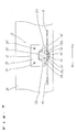
- the magnetic tape cleaner comprises a tape scraper 1 securely mounted by screws 2 and 2′ on a base 3 having a magnetic head not shown provided thereon.
- the tape scraper 1 comprises a C-shaped scraper body 4 having a width larger than a width of a magnetic tape 9 and disposed so that an opening 4a is faced to a tape running path.
- Scraper blades 5 and 5′ for scraping magnetic powder 6 out of the recording face of the magnetic tape 9 are secured to recesses 4b and 4c of side walls of the scraper body 4.
- the conventional tape cleaner comprises suction means 7 such as a vacuum pump which is connected to the space within the scraper body 4 through a hose 8 which extends through the rear wall of the scraper body 4.
- the magnetic powder 6 on the recording face of the magnetic tape 9 is scraped by the scraper blade 5′ positioned on a downstream side of the tape running path and floats within the space of the scraper body 4.
- the suction means 7 attracts the floating magnetic powder through an inlet 8a of the hose 8. While the magnetic tape 9 is running in a direction indicated by an arrow B of Fig. 14, after the scraper blade 5 on the downstream side of the tape running path scrapes the magnetic powder 6 out of the recording face of the magnetic tape 9, it is sucked by the suction means 7 in the similar manner.
- Such a conventional magnetic tape cleaner is provided with suction means 7 such as a vacuum pump for sucking the magnetic powder scraped by the tape scraper 1 and therefore the scraped magnetic powder is prevented from being again attached to the recording face of the magnetic tape 9.
- suction means 7 such as a vacuum pump for sucking the magnetic powder scraped by the tape scraper 1 and therefore the scraped magnetic powder is prevented from being again attached to the recording face of the magnetic tape 9.
- the suction means 7 is required in order to remove the magnetic powder 6 out of the scraper, the magnetic instrument having such a magnetic tape cleaner provided therein is advantageously large-sized.
- the instrument is expensively manufactured because the suction means has high cost.
- a magnetic tape cleaner comprising; tape scraper means engaging a magnetic tape to scrape magnetic powder on a recording face of said magnetic tape; and magnet means to attract said scraped magnetic powder.
- the magnet means may be only a magnet or a combination of a magnet and a yoke member connected to the magnet and including a pair of pole pieces having a gap provided therebetween.
- the magnetic tape cleaner of the invention is compact and inexpensively manufactured because no suction means of large size and of high cost is required.
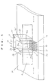
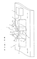
- FIGs. 1 through 3 there is illustrated a magnetic tape cleaner constructed in accordance with one embodiment of the invention so that it is suitably used for a horizontal type magnetic instrument such as a magnetic recording and reproducing apparatus.
- the magnetic tape cleaner 10 comprises tape scraper means 12 engaging a magnetic tape 16 to scrape magnetic powder 18 on a recording face of the magnetic tape 16 and magnet means 14 to attract the scraped magnetic powder 18.
- the tape scraper means 12 comprises a tape scraper 20 substantially identical to that of the conventional magnetic tape cleaner and including a C-shaped scraper body 22 of nonmagnetic material such as plastics having an opening 22a provided and securely mounted by screws 24 and 24′ on a base or chassis 26 having a magnetic head not shown and a pair of scraper blades 28 and 28′ securely mounted on the scraper body 22 at its recessed edges 22b and 22c thereof, respectively and having edges 28a and 28′a to scrape the magnetic powder 18 from the recording face of the magnetic tape 16.
- the scraper body 22 is positioned so that the opening 22a is faced toward a front face of the magnetic instrument.
- the magnetic tape 16 has its running path along which it moves while it engages the tape scraper 20.
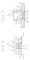
- the magnet means 14 comprises a magnet 30 positioned within a containing hole 32 provided in the base 26 in alignment with a space 23 of the scraper body 22.
- the space 23 of the scraper body 22 is defined by the walls of the scraper body 22 and the portion of the magnetic tape 16 engaging the scraper blades 28 and 28′.
- the upper face of the magnet 30 is located at a position lower than the upper face of the base 26 as shown in Fig. 3 so as to form a recess 32a in the containing hole 32.
- the magnet 30 is held in the containing hole 32 by a cover 34 which is detachably mounted on the base 26 at its recess 26a on the bottom thereof.
- the cover 34 is securely mounted on the base 26 by screws 35 and 35′.
- the magnetic powder 18 on the recording face of the magnetic tape 16 is scraped by the edge 28′a of the scraper blade 28′ positioned on a downstream side of the tape running path and is floating within the space 23 of the scraper body 22.
- the magnetic powder 18 floating in this manner is magnetically attracted by the magnet 30 of the magnet means 14 so that it is collected within the recess 32a of the containing hole 32. After much magnetic powder is collected within the recess 32a by attraction by the magnet 30, it can be removed out of the magnet 30 withdrawn from the base 26 by detaching the cover 34.
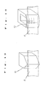
- Figs. 4 and 5 show a magnetic tape cleaner 10 constructed in accordance with a modification of the magnetic tape cleaner of Figs. 1 through 3 so that it is suitably used for a vertical type magnetic instrument.
- the same numerals designate the same components.
- the scraper body 22 is mounted on the base 26 so that the opening 22a is faced upwardly and secured by the screws 24 and 24′ thereto.
- the magnet is positioned within the space 23 of the scraper body 22 and held by front and rear covers 34 and 34′ indicated by two dotted and solid line in Fig. 4 and detachably secured to the scraper body 22 by the screws 35 and screws 35′ not shown, respectively.
- the magnet 30 can be withdrawn by the cover 34 or 34′ being detached from the scraper body 22.
- the magnet 30 is thinner than the depth of the space 23 of the scraper body 22 as shown in Figs. 4 and 5.
- the space 23 of the scraper body 22 is defined by the side walls of the scraper body 22, the portion of the magnetic tape 16 engaging the scraper blades 28 and 28′ and the magnet 30.
- the magnetic powder 18 on the recording face of the magnetic tape 16 is scraped by either of the scraper blades 28 and 28′ in accordance with the tape running direction and attracted onto the upper face of the magnet 30.
- the magnetic powder 18 can be removed out of the magnet 30 by detaching the cover 34 or 34′ as aforementioned.
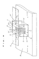
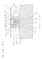
- Figs. 6 through 8 show a magnetic tape cleaner constructed in accordance with another embodiment so that it is suitably used for a horizontal type magnetic instrument.
- the same numerals designate the same components.
- the tape scraper means 12 of Figs. 6 through 8 is substantially identical to that of Figs. 1 through 3.
- the magnet means 14 of Figs. 6 through 8 comprises a yoke member 36 as well as the magnet 30.
- the yoke member 36 comprises a yoke body 38 of magnetic material such as soft iron having a pair of pole pieces 40 and 40′ and a connecting portion 42 physically and magnetically connecting the pole pieces 40 and 40′ and a mounting portion 44 in the form of a screw which spirally engages the tapped enlarged hole portion 32b of the containing hole 32.
- the magnet 30 is positioned in the yoke body 38 so that it is positioned between the pole pieces 40 and 40′ with its poles facing thereto.
- the yoke body 38 and the mounting portion 44 may be formed integrally with each other. It will be understood that the yoke member 36 together with the magnet 30 can be withdrawn from the base 26 by disengaging the mounting portion 44 from the containing hole 32 at its enlarged hole portion 32b.
- the yoke member 36 has a height h smaller than a thickness d of the base 26 so that the upper space 32a of the containing hole 32 is formed communicating with the space 23 of the scraper body 22.
- a magnetic gap 46 is formed between the pair of pole pieces 40 and 40′ within the upper space 32a of the containing hole 32 so that magnetic flux 48 from the magnet 30 passes through the magnetic gap 46. It should be noted that attracting force is concentrated at the magnetic gap 46.
- the magnetic powder 18 on the recording face of the magnetic tape 16 is scraped by the edge 28′a of the scraper blade 28′ positioned on a downstream side of the tape running path and is floating within the space 23 of the scraper body 22.
- the magnetic powder 18 floating in this manner is magnetically attracted by the magnet 30 and the pole pieces 40 and 40′ of the yoke member 36 so that it is collected within the upper space 32a of the containing hole 32.
- the yoke member 36 serves to attract the magnetic powder 18 by high magnetic force because the magnetic flux 48 is collected at the magnetic gap 46 between the pole pieces 40 and 40′. This means that even the magnet 30 of smaller size having lower magnetic force can sufficiently attract the magnetic powder 18 floating within the space 23 of the scraper body 22. It should be noted that the leakage of magnetic flux decreases because of the magnetic flux 48 collected at the magnetic gap 46. This advantageously prevents the magnet 30 from adversely affecting the magnetic tape 16.
- Fig. 9 shows the magnetic tape cleaner 10 substantially identical to that of Figs. 6 through 8 except for a modified yoke member 36.
- the modified yoke member 36 has no connecting portion 42 of magnetic material, but a connecting portion 42′ of material having low permeability.
- the pair of pole pieces 40 and 40′ are physically connected by the connecting portion 42′.
- the mounting portion 44′ is formed of nonmagnetic material. This is more advantageous because magnetic flux passing through the connecting portion 42′ decreases and the density of magnetic flux increases at the magnetic gap 46, which causes higher attracting force to be obtained.
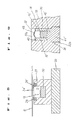
- Figs. 10 and 11 show a magnetic tape cleaner 10 constructed in a manner substantially identical to that of Figs. 6 through 8, but so constructed that it is suitably used for a vertical type magnetic instrument.
- the same numerals designate the same components.
- the scraper body 22 is mounted on the base 26 so that the opening 22a is faced upwardly and secured by the screws 24 and 24′ thereto.
- the yoke member 36 together with the magnet 30 is positioned within the space 23 of the scraper body 22 and held by the front and rear covers 34 and 34′ indicated by two dotted and solid line in Fig. 10 and detachably secured to the scraper body 22 by the screws 35 and screws 35′ not shown, respectively.
- the yoke member 36 and the magnet 30 can be withdrawn by the cover 34 or 34′ being detached from the scraper body 22.
- the hight h′ of the yoke member 36 is so set to be smaller than the depth d′ of the space 23 of the scraper body 22 in the same manner as that of the cleaner of Figs. 6 through 8 and that the yoke member 36 is not required to have the mounting portion.
- the connecting portion 42 may be of magnetic material, but preferably of material having low permeability because this causes the magnetic flux to be more collected at the magnetic gap 46.
- the magnetic powder 18 on the recording face of the magnetic tape 16 is scraped by either of the scraper blades 28 and 28′ in accordance with the tape running direction and attracted onto the pole pieces 40 and 40′ of the yoke member 36 and the upper face of the magnet 30.
- the magnetic powder 18 can be removed out of the yoke member 36 together with the magnet 30 by detaching the cover 34 or 34′ as aforementioned.
- the tape scraper 20 comprises the pair of scraper blades 28 and 28′, it may comprise a single scraper blade 50 as shown in Fig. 12 or a perforated plate 52 as shown in Fig. 13.
Landscapes
- Cleaning In General (AREA)
- Magnetic Record Carriers (AREA)
Applications Claiming Priority (4)
| Application Number | Priority Date | Filing Date | Title |
|---|---|---|---|
| JP1988142451U JPH0617246Y2 (ja) | 1988-10-31 | 1988-10-31 | テープクリーニング装置 |
| JP142451/88U | 1988-10-31 | ||
| JP58832/89U | 1989-05-22 | ||
| JP5883289 | 1989-05-22 |
Publications (2)
| Publication Number | Publication Date |
|---|---|
| EP0367518A2 true EP0367518A2 (de) | 1990-05-09 |
| EP0367518A3 EP0367518A3 (de) | 1991-04-10 |
Family
ID=26399844
Family Applications (1)
| Application Number | Title | Priority Date | Filing Date |
|---|---|---|---|
| EP19890311144 Withdrawn EP0367518A3 (de) | 1988-10-31 | 1989-10-27 | Magnetbandreiniger |
Country Status (2)
| Country | Link |
|---|---|
| US (1) | US5045962A (de) |
| EP (1) | EP0367518A3 (de) |
Families Citing this family (6)
| Publication number | Priority date | Publication date | Assignee | Title |
|---|---|---|---|---|
| JP2822248B2 (ja) * | 1989-12-28 | 1998-11-11 | ソニー株式会社 | 記録再生装置のテープクリーナ |
| SE469099B (sv) * | 1991-08-14 | 1993-05-10 | Nokia Data Ab | Foermagnetiseringshuvud |
| JPH06251556A (ja) * | 1993-02-24 | 1994-09-09 | Sony Corp | 磁気記録再生装置のクリーニング装置 |
| US6700743B2 (en) | 2002-02-11 | 2004-03-02 | Imation Corp. | Tape media cleaning/finishing device |
| US7369362B2 (en) * | 2005-03-16 | 2008-05-06 | Quantum Corporation | Tape cleaning apparatus |
| US8199430B2 (en) * | 2007-07-13 | 2012-06-12 | Hitachi Maxell, Ltd. | Tape device having a tape cleaning structure |
Family Cites Families (13)
| Publication number | Priority date | Publication date | Assignee | Title |
|---|---|---|---|---|
| DE400400C (de) * | 1922-03-16 | 1924-08-19 | Herbert Frood | Hilfsgeraet fuer Sprechmaschinen |
| US2591121A (en) * | 1947-05-10 | 1952-04-01 | Dings Magnetic Separator Co | Crossbelt magnetic separator |
| US3091794A (en) * | 1961-02-21 | 1963-06-04 | Ampex | Tape cleaning apparatus |
| US3602940A (en) * | 1968-12-16 | 1971-09-07 | Ibm | Magnetic recording tape cleaner |
| US3701178A (en) * | 1970-12-02 | 1972-10-31 | Jonathan C Kuntz | Cassette tape cleaner |
| SU467401A1 (ru) * | 1973-02-08 | 1975-04-15 | Предприятие П/Я В-2672 | Устройство дл очистки носител записи от про вл ющего ферропорошка |
| JPS5827588B2 (ja) * | 1976-02-04 | 1983-06-10 | 株式会社日立製作所 | 磁気テ−プ装置 |
| JPS5360619A (en) * | 1976-11-12 | 1978-05-31 | Hitachi Ltd | Magnetic tape device |
| DE7801442U1 (de) * | 1978-01-19 | 1978-07-20 | Basf Ag, 6700 Ludwigshafen | Vorrichtung zum reinigen von folienbahnen mit einer magnetschicht |
| JPS6028544B2 (ja) * | 1980-11-12 | 1985-07-05 | ブンリ工業株式会社 | マグネチックベルトコンベア式分離装置 |
| SU974405A1 (ru) * | 1981-05-20 | 1982-11-15 | Московский Ордена Трудового Красного Знамени Электротехнический Институт Связи | Устройство дл очистки магнитной ленты |
| JPH0646452B2 (ja) * | 1987-09-21 | 1994-06-15 | 富士写真フイルム株式会社 | 磁気テープクリーニング装置 |
| US4947270A (en) * | 1988-03-10 | 1990-08-07 | Paynter Iii Lewis | Video cassette rewind apparatus |
-
1989
- 1989-10-27 EP EP19890311144 patent/EP0367518A3/de not_active Withdrawn
- 1989-10-31 US US07/429,838 patent/US5045962A/en not_active Expired - Fee Related
Also Published As
| Publication number | Publication date |
|---|---|
| US5045962A (en) | 1991-09-03 |
| EP0367518A3 (de) | 1991-04-10 |
Similar Documents
| Publication | Publication Date | Title |
|---|---|---|
| US8256122B2 (en) | Magnetic two part scraping tool | |
| EP0110212A2 (de) | Luftlagermagnetkopfgleiter-Montage | |
| EP0367518A2 (de) | Magnetbandreiniger | |
| JPH1159872A (ja) | 部品整列装置 | |
| US2994489A (en) | Vacuum friction pad for tape recorders | |
| SU913921A3 (en) | Magnetic separator with permanent magnets for cleaning liquids from magnetized particles | |
| JPS637291A (ja) | 保持装置 | |
| US6212036B1 (en) | Mechanically actuated tape head cleaner having debris removal vacuum | |
| JPH0617246Y2 (ja) | テープクリーニング装置 | |
| JPH0617247Y2 (ja) | テープクリーニング装置 | |
| US3975789A (en) | Compliant tape cleaner for magnetic recording tapes | |
| JPS5919987Y2 (ja) | テ−プ清掃装置 | |
| CN218044933U (zh) | 清洁设备和清洁系统 | |
| CA1139234A (en) | Pickup cartridge of moving coil type for phonograph | |
| JPS60128742U (ja) | 磁性体の分離装置 | |
| JPS58158085A (ja) | 磁気シ−トカセツト | |
| JPS57182459A (en) | Picture recording unit | |
| JPH0447831B2 (de) | ||
| JPS6010276A (ja) | 現像装置 | |
| US2910632A (en) | Magnet system | |
| JPH1051128A (ja) | 表面実装型コネクタの実装構造及び方法並びにpcカード構造 | |
| JPS6228189A (ja) | 吸着装置 | |
| KR20250089200A (ko) | 감지용 자석이 구비된 탈부착용 자석 구조체 | |
| Yamada et al. | GT target", A new high rate sputtering target of magnetic materials | |
| KR910003734Y1 (ko) | 이퀄라이즈 노브 (Equalize Knob) 의 이송장치 |
Legal Events
| Date | Code | Title | Description |
|---|---|---|---|
| PUAI | Public reference made under article 153(3) epc to a published international application that has entered the european phase |
Free format text: ORIGINAL CODE: 0009012 |
|
| AK | Designated contracting states |
Kind code of ref document: A2 Designated state(s): DE FR GB IT |
|
| PUAL | Search report despatched |
Free format text: ORIGINAL CODE: 0009013 |
|
| RHK1 | Main classification (correction) |
Ipc: G08B 15/00 |
|
| AK | Designated contracting states |
Kind code of ref document: A3 Designated state(s): DE FR GB IT |
|
| RHK1 | Main classification (correction) |
Ipc: G11B 23/50 |
|
| STAA | Information on the status of an ep patent application or granted ep patent |
Free format text: STATUS: THE APPLICATION IS DEEMED TO BE WITHDRAWN |
|
| 18D | Application deemed to be withdrawn |
Effective date: 19911011 |