EP4101800A1 - Unité de réservoir de fil pour un poste de travail d'une machine textile - Google Patents
Unité de réservoir de fil pour un poste de travail d'une machine textile Download PDFInfo
- Publication number
- EP4101800A1 EP4101800A1 EP22177708.9A EP22177708A EP4101800A1 EP 4101800 A1 EP4101800 A1 EP 4101800A1 EP 22177708 A EP22177708 A EP 22177708A EP 4101800 A1 EP4101800 A1 EP 4101800A1
- Authority
- EP
- European Patent Office
- Prior art keywords
- thread
- coupling element
- guide arm
- thread guide
- storage unit
- Prior art date
- Legal status (The legal status is an assumption and is not a legal conclusion. Google has not performed a legal analysis and makes no representation as to the accuracy of the status listed.)
- Granted
Links
Images


Classifications
-
- B—PERFORMING OPERATIONS; TRANSPORTING
- B65—CONVEYING; PACKING; STORING; HANDLING THIN OR FILAMENTARY MATERIAL
- B65H—HANDLING THIN OR FILAMENTARY MATERIAL, e.g. SHEETS, WEBS, CABLES
- B65H57/00—Guides for filamentary materials; Supports therefor
- B65H57/06—Annular guiding surfaces; Eyes, e.g. pigtails
-
- B—PERFORMING OPERATIONS; TRANSPORTING
- B65—CONVEYING; PACKING; STORING; HANDLING THIN OR FILAMENTARY MATERIAL
- B65H—HANDLING THIN OR FILAMENTARY MATERIAL, e.g. SHEETS, WEBS, CABLES
- B65H59/00—Adjusting or controlling tension in filamentary material, e.g. for preventing snarling; Applications of tension indicators
- B65H59/005—Means compensating the yarn tension in relation with its moving due to traversing arrangements
-
- B—PERFORMING OPERATIONS; TRANSPORTING
- B65—CONVEYING; PACKING; STORING; HANDLING THIN OR FILAMENTARY MATERIAL
- B65H—HANDLING THIN OR FILAMENTARY MATERIAL, e.g. SHEETS, WEBS, CABLES
- B65H57/00—Guides for filamentary materials; Supports therefor
- B65H57/14—Pulleys, rollers, or rotary bars
-
- B—PERFORMING OPERATIONS; TRANSPORTING
- B65—CONVEYING; PACKING; STORING; HANDLING THIN OR FILAMENTARY MATERIAL
- B65H—HANDLING THIN OR FILAMENTARY MATERIAL, e.g. SHEETS, WEBS, CABLES
- B65H59/00—Adjusting or controlling tension in filamentary material, e.g. for preventing snarling; Applications of tension indicators
- B65H59/10—Adjusting or controlling tension in filamentary material, e.g. for preventing snarling; Applications of tension indicators by devices acting on running material and not associated with supply or take-up devices
-
- B—PERFORMING OPERATIONS; TRANSPORTING
- B65—CONVEYING; PACKING; STORING; HANDLING THIN OR FILAMENTARY MATERIAL
- B65H—HANDLING THIN OR FILAMENTARY MATERIAL, e.g. SHEETS, WEBS, CABLES
- B65H63/00—Warning or safety devices, e.g. automatic fault detectors, stop-motions ; Quality control of the package
- B65H63/02—Warning or safety devices, e.g. automatic fault detectors, stop-motions ; Quality control of the package responsive to reduction in material tension, failure of supply, or breakage, of material
-
- B—PERFORMING OPERATIONS; TRANSPORTING
- B65—CONVEYING; PACKING; STORING; HANDLING THIN OR FILAMENTARY MATERIAL
- B65H—HANDLING THIN OR FILAMENTARY MATERIAL, e.g. SHEETS, WEBS, CABLES
- B65H63/00—Warning or safety devices, e.g. automatic fault detectors, stop-motions ; Quality control of the package
- B65H63/04—Warning or safety devices, e.g. automatic fault detectors, stop-motions ; Quality control of the package responsive to excessive tension or irregular operation of apparatus
-
- B—PERFORMING OPERATIONS; TRANSPORTING
- B65—CONVEYING; PACKING; STORING; HANDLING THIN OR FILAMENTARY MATERIAL
- B65H—HANDLING THIN OR FILAMENTARY MATERIAL, e.g. SHEETS, WEBS, CABLES
- B65H71/00—Moistening, sizing, oiling, waxing, colouring or drying filamentary material as additional measures during package formation
- B65H71/005—Oiling, waxing by applying solid wax cake during spooling
-
- B—PERFORMING OPERATIONS; TRANSPORTING
- B65—CONVEYING; PACKING; STORING; HANDLING THIN OR FILAMENTARY MATERIAL
- B65H—HANDLING THIN OR FILAMENTARY MATERIAL, e.g. SHEETS, WEBS, CABLES
- B65H2701/00—Handled material; Storage means
- B65H2701/30—Handled filamentary material
- B65H2701/31—Textiles threads or artificial strands of filaments
-
- D—TEXTILES; PAPER
- D01—NATURAL OR MAN-MADE THREADS OR FIBRES; SPINNING
- D01H—SPINNING OR TWISTING
- D01H2700/00—Spinning or twisting machines; Drafting devices
- D01H2700/22—Winding devices for spinning mules
Definitions
- a controlled thread storage unit in front of the traversing devices along a thread path for winding bobbins, e.g. conical cross-wound bobbins.
- These thread storage units are used to adapt the thread sagging that occurs when the bobbins are wound up to the constant thread delivery speed, for example of a spinning device or spinning cop take-off device.
- the package is usually held during the winding process or the bobbin cycle in a pivoted creel of a traversing device downstream winding device and is usually driven by a friction roller via a frictional connection or individually.
- the winding speed of the take-up package corresponds to the constant thread delivery speed, for example by the spinning device, depending on the diameter of the wound-up package.
- the thread is defined across the width of the bobbin, in particular crosswise, by means of the traversing device. Due to the constant yarn delivery speed, the yarn periodically loosens, which is why, in order to maintain a desired yarn tension, there is a need to compensate for the slack in the course of the shortening of the working path of the yarn along the yarn travel path.
- the object of the invention is to provide a thread storage unit which particularly reliably enables the thread tension to be maintained as constant as possible during the winding process.
- the invention solves the problem by a thread storage unit with the features of claim 1, by a work station comprising such a thread storage unit according to the features of claim 8 and by a method for setting a thread tension at such a work station according to the features of claim 12.
- Advantageous developments of the Invention are set out in the dependent claims.
- the thread guide arm is freely rotatably mounted and has a magnetically acting first coupling element that is arranged at a distance from the pivot axis.
- the drive unit has a second magnetic coupling element, which is arranged adjustably relative to the first coupling element and acts magnetically repulsively on the first coupling element.
- the second magnetic coupling element is arranged on the drive unit so that it can be brought into operative connection with the first coupling element via the drive unit, wherein an adjustment of the second coupling element in the direction of the first coupling element causes a displacement of the first coupling element in the same direction and thus a pivoting of the thread guide arm.
- the thread guide arm according to the present invention is a departure from previously known thread storage units, in which the thread guide arm is directly forced to rotate by a drive shaft of the drive unit, for example via a stationary bearing, on the drive shaft, and the force is consequently transmitted strictly by components touching one another along the power flow now freely rotatable, stored in particular on the drive shaft of the drive unit.
- the rotational force generated by the drive shaft can be transmitted without contact to the thread guide arm using magnetically acting means.
- the first and second coupling elements are aligned with one another in such a way that they exert a repelling magnetic effect on one another.
- the first coupling element is displaced in accordance with the direction of movement of the second coupling element, which results in the connection of the first coupling element with the thread guide arm, it is pivoted about the pivot axis.
- the thread guide arm is displaced about its pivot axis without contact via the drive unit, depending on the set position of the second coupling element arranged on the drive unit.
- the thread guide arm By pivoting the thread guide arm about the pivot axis into the thread path, the thread guide arm creates a loop-like course of the thread in the area of the thread storage unit, with the thread guide arm preferably being able to engage with the thread in the area between two thread guide rollers or eyelets arranged along a thread path. to create a defined loop course.
- a non-contact adjustment of the thread guide arm is effected by the drive unit via the two coupling elements. If there is excess thread during the winding process, which leads to a decrease in thread tension, then this is taken up in a loop between the preferably provided pair of thread-guiding rollers or eyelets and the thread-guiding arm.
- the required thread length is released from the loop by moving the thread guide arm back, with the second coupling element being adjusted via the drive unit in such a way for this purpose that the thread guide arm is pivoted in an opposite direction pushing away the thread, with a reverse pivoting of the thread guide arm thereby the thread tension acting on the thread guide arm.
- the thread guide arm thus follows the restoring movement of the second coupling element and releases the required thread length in a defined manner.
- the thread storage unit thus makes it possible to keep the thread tension constant at a precise and high frequency via the freely rotatable thread guide arm, so that a winding process can also be carried out at particularly high winding speeds, with the production of both cylindrical and conical winding packages being particularly reliable.
- the thread guide arm is adjusted in the direction of the thread or in the opposite direction without changing the distance between the first and second coupling element and thus without changing the magnetic spring force resulting from the distance between the two coupling elements.
- An adjustment movement of the thread guide arm can be regulated in a preferred manner via a control system that activates the drive unit and a sensor unit that can be connected to the control system for transmitting detected sensor information.
- the control system is preferably designed to evaluate and evaluate the transmitted sensor information and to activate the drive unit in a defined manner based on the result of the evaluation.
- the control system can preferably include a control unit and an evaluation and evaluation unit. These units can be one and the same unit or different units. Two units can also be implemented with a single unit.
- control system can also be part of the thread storage device or a separate component. Also, the arrangement of the control system can be freely selected. Thus, the control system can be provided in a work station, which includes the thread storage unit, in a central machine control and/or away from the textile machine. A redundant control by providing two such control systems that check or can check one another can also be possible.
- the sensor unit that can be connected to the control system can preferably be used to detect the rotational movement and/or the position of the thread guide arm, whereby changes in the distance between the two coupling elements resulting from a change in the thread tension can also be determined via the sensor information recorded by the sensor unit. If the thread guide arm is in a displaced position in the direction of the second coupling element compared to the position set by the control system, ie the distance between the first coupling element and the second is reduced Coupling element, then the acting between the first and second coupling element magnetically generated spring force increases.
- the thread storage unit thus makes it possible to keep the thread tension constant with a particularly precise and high frequency.
- the configuration of the displacement of the second coupling element relative to the first coupling element by means of the drive unit can in principle take place in any manner.
- linear drives are conceivable here, which linearly adjust the second coupling element in the direction of the first coupling element transversely to the pivot axis and thus bring about a displacement of the thread guide arm.
- the second coupling element is arranged on a carrier that can be adjusted by means of the drive unit, in particular coaxially, about the pivot axis of the thread guide arm.
- the second coupling element can be adjusted about the pivot axis of the thread guide arm, with the second coupling element being arranged on a carrier connected to the drive unit for this purpose.
- the rotation of the carrier about the pivot axis of the thread guide arm makes it possible to use particularly space-saving rotary drives to adjust the second coupling element.
- a rotation of the second coupling element which is particularly preferably arranged at the same distance from the pivot axis as the first coupling element, offers a particularly uniform and reliable adjustment, so that a particularly precise displacement of the thread guide arm can be carried out by the control system via a displacement of the carrier.
- the arrangement of the first coupling element on the thread guide arm is basically free selectable. According to a particularly preferred embodiment of the invention, it is provided that the first coupling element is detachably attached to the thread guide arm and/or the second coupling element is detachably attached to the drive unit.
- This embodiment of the invention makes it possible to easily change the first and/or second coupling element if necessary, so that adaptations to different production conditions, which may require magnetic effects that differ from one another, can be made in a simple manner. In addition, maintenance and repair work can be carried out particularly easily and quickly.
- the drive unit for displacing the second coupling element, in particular the carrier can in principle be freely selected, with different motor drives being able to be used here.
- the drive unit has an electric motor, in particular a stepper motor, with a drive shaft which is non-rotatably connected to the carrier and on which the thread guide arm is freely rotatably mounted.
- the guide arm particularly preferably has a bearing unit, in particular a bushing element, at a free end, by means of which the thread guide arm can be placed on the free end of the drive shaft.
- the bearing unit is designed to support the thread guide arm in a freely rotatable manner on the free end of the drive shaft, independently of a rotary movement of the drive shaft, ie torque-free.
- the thread guide arm preferably has a thread guide section at its other free end, in particular a thread guide eyelet or roller, for contacting and guiding the thread. This allows the leverage of the yarn guide arm to be used to the maximum extent.
- other arrangement locations selected as required, both of the bearing unit and of the thread guide section along the longitudinal axis of the thread guide arm are also conceivable.
- the drive shaft serves to accommodate the thread guide arm in a freely rotatable manner, whereby a freely rotatable mounting or free rotary mobility is generally understood to mean a torque-free connection between the drive shaft and the thread guide arm, so that the drive shaft alone is used for pivoting, in particular for pivoting mounting, of the Thread guide arm is used on this, however transmits no torque.
- a corresponding design of the thread storage unit also enables its particularly compact design, with it being ensured in a particularly reliable manner that a second coupling element arranged on the carrier can be adjusted around the drive shaft over the same circumference as the first coupling element, which is at a corresponding distance from the Axis of the drive shaft is arranged on the yarn guide arm.
- first and/or second coupling element can be designed as electromagnets, the magnetic fields of which are aligned in such a way that they produce an effect that repels one another.
- the electromagnets can be controlled via the control system, so that different magnetic fields can be generated via them if necessary, so that the repulsion effect can be set and, in particular, regulated via the corresponding control system.
- the first coupling element and the second coupling element are designed as permanent magnets.
- the use of permanent magnets as coupling elements, which are arranged in a correspondingly aligned manner on the thread guide arm and the carrier, represents a particularly simple, low-maintenance and cost-effective way of providing a magnetic repulsion effect.
- the desired repulsion effect can be determined by selecting the permanent magnets.
- connection of the carrier to the drive unit in particular to a preferably provided drive shaft of an electric motor, can be established by simple flange connections.
- the carrier is arranged on a coupling disk which is arranged coaxially to the drive shaft and is connected to the drive shaft in a rotationally fixed manner.
- the use of a coupling disk ensures a particularly reliable displacement of the carrier and the second coupling element, which is connected to the carrier, about the pivot axis of the thread guide arm.
- the coupling disk can bear against a corresponding counter-surface of an advantageously provided electric motor for planar guidance.
- a sensor unit is used to detect the rotational movement and/or position of the thread guide arm, in particular to detect deviations from the position of the thread guide arm compared to the position set by the control system via the drive unit, which can basically be arranged at any desired location.
- the sensor unit is designed and arranged to detect the angle of rotation and/or the position of a connection element which is connected to the thread guide arm in a rotationally fixed manner and is arranged coaxially to the drive shaft, with the sensor unit more preferably being arranged coaxially to the connection element.
- a connecting element connected to the thread guide arm in a rotationally fixed manner extends in sections into the sensor unit, which is arranged at a distance from the end of the drive shaft.
- a corresponding arrangement of the sensor unit in particular the arrangement preferably provided coaxially to the connection element, enables a particularly precise detection of the rotational movement and/or position of the thread guide arm and also allows a particularly compact design of the thread storage unit.
- a work station in particular a spinning or winding station, of a textile machine
- the work station is also equipped with a yarn feeding device for feeding a yarn, a traversing device for traversing the supplied yarn and a yarn winding device for winding the traversed yarn onto a package.
- the yarn feeding device, the traversing device and the yarn winding device are arranged along a yarn running path for processing the yarn accordingly.
- the thread travel path is such a path from the delivery point to the winding point, along which the thread runs during its bobbin journey without being influenced by the thread storage unit.
- the yarn storage unit is also arranged along the yarn path between the yarn feed device and the traversing device in order to urge the running yarn out of the yarn path during the bobbin travel by means of the pivoting movement of the yarn guide arm.
- the thread guide arm is particularly preferably arranged along the thread path between two thread guide rollers or eyelets, over which or through which the thread is guided during its bobbin journey.
- the thread guide rollers or eyelets can be carried by a paraffining device upstream of the traversing device along the thread path and can be arranged upstream of a paraffin body of the paraffining device.
- the work station is assigned a control system as described above and a sensor unit as described above that can be connected to the control system for exchanging information, the sensor unit being designed to detect the rotational movement and/or position of the thread guide arm and to transmit sensor information to the control system and arranged.
- the control system is preferably designed to evaluate and evaluate the transmitted sensor information and to activate the drive unit in a defined manner based on the result of the evaluation. More preferably, the control system is designed to control the drive unit for controlling the thread tension and/or the storage quantity of the guided thread and also preferably the sensor unit for retrieving sensor information.
- a rest position of the thread guide arm is provided in a position crossing the thread path, in which position the thread guided by the thread guide arm is pushed out of the thread path during the bobbin travel.
- the thread storage unit is arranged with the thread guide arm along the thread path in such a way that a rest position of the thread guide arm, which corresponds to a zero position of the drive unit, is outside the thread path and in the direction in which the thread guide arm forces the thread out of the thread path. It can thus be ensured that the thread guide arm can be reset solely by the force effect of the thread generated in the direction of the thread path when it is deflected from the thread path.
- the thread storage unit can have further magnetically or mechanically spring-acting coupling elements, which are directed counter to the direction of magnetic force action of the first and second coupling element and are designed to reset the thread guide arm as required against the direction of deflection by the first and second coupling element.
- These further coupling elements can be coupled in a preferred manner corresponding to the first and second coupling element with a drive unit and a control system coupled thereto, such as the control system described above, and the sensor unit or another sensor unit in order to Thread guide arm to pivot as needed.
- a method for adjusting a thread tension of a running thread at a work site is proposed.
- the sensor unit transmits sensor information about the rotational movement and/or position of the thread guide arm to a control system assigned to the work station.
- the control system evaluates a magnetic force acting between the first and second coupling element to identify a thread tension exerted on the thread and, in the event of a deviation from a limit value or limit value range for the thread tension that is assessed as impermissible, controls the drive unit to change the position of the thread Yarn guide arm, as described above, defined.
- the thread tension can be kept constant during the bobbin cycle and regulated as required.
- figure 1 shows a perspective schematic view of a thread storage unit 1 according to an exemplary embodiment, which is connected to a connection plate 17 for arrangement at a work station, in particular a spinning or winding station, of a textile machine, not shown here.
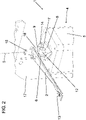
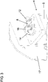
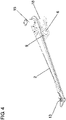
- Figures 2 to 4 show a perspective schematic view of an enlarged representation of a portion of the in figure 1 shown thread storage unit 1 and a perspective schematic representation of a thread guide arm 2 of this thread storage unit 1.
- the thread storage unit 1 has a thread guide arm 2 which is arranged at the work site with a thread guide eyelet 13 arranged at its free end in the thread travel path F of a thread to be wound onto a take-up bobbin, the thread being guided through the thread guide eyelet 13 .
- the thread guide arm 2 is pivotably mounted on a drive shaft 16 of an electric motor 5 of a drive unit 4 of the thread store unit 1, with the thread guide arm 2 having a bushing 18 for this purpose on the free end of the drive shaft 16, so that the thread guide arm 2 opens torque-free the drive shaft 16 is mounted.
- the bushing 18 is also connected to a holder 9 which is connected to the thread guide arm 2 and has an opening for receiving a first coupling element 6 designed as a permanent magnet.
- the drive shaft 16 of the electric motor 5 is non-rotatably connected to a coupling disk 14 which is arranged coaxially with the drive shaft 16 .
- a carrier 8 is arranged on the coupling disk 14 and has a further socket 12 for receiving a further permanent magnet as the second coupling element 7 .
- the permanent magnets on the thread guide arm 2 and the carrier 8 are aligned with one another in such a way that they exert a magnetic effect that repels one another.
- a rotation of the coupling disk 14 via the reversing electric motor 5 thus causes a corresponding non-contact pivoting of the thread guide arm 2 about the drive shaft 16, which defines a pivot axis S, with the control of the electric motor 5 via a control system not shown here via the connection 19.
- a sensor unit 3 arranged above - based on the drawing - of the drive shaft 16 on a housing cover 11 of the housing 10 is used to detect the position of the thread guide arm 2 in turn extends in the direction of the longitudinal axis of the drive shaft 16 .
- About the sensor unit 3 can be particularly reliable at least the rotary movement or Determines the position of the yarn guide arm 2 and detects deviations of the yarn guide arm 2 from the position set by the drive unit 4 by transmitting corresponding sensor information to the control system. If, for example, the thread tension increases, this causes a displacement of the thread guide arm 2 in the direction of the second coupling element 7 against the spring force generated by the magnetic repulsion effect. Proceeding from this, the coupling disk 14 can then be shifted back via the control system. If, for example, the thread tension decreases as the thread sags, this causes the second coupling element 7 to be displaced by a rotation of the drive shaft 16 and the carrier 8 coupled to it, together with the coupling disc 14 and the permanent magnet, in the direction of the thread guide arm 2.
- the magnetic repulsion effect causes the thread guide arm 2 moves in the same direction, whereby the guided thread is pushed away from its thread path or further away from it and a thread loop is formed or enlarged. In this way, a substantially constant thread tension can be achieved and ensured during the entire winding process or the bobbin cycle.
- figure 5 shows a perspective schematic view of an embodiment of an arrangement of the thread storage unit 1 at the work station, not shown, where the work station can be a spinning or winding station.
- the thread storage unit 1 is arranged along a thread travel path F, which runs from a thread feed device, not shown, in the direction of a traversing device, not shown, upstream of a paraffining device 20, which is only shown schematically and in part, and is upstream of the traversing device along the thread travel path F.
- the paraffining device 20 has a holder 22 underneath, on which two thread guide rollers 21 are rotatably held, via which the thread can be guided along the thread path in a partially wrapped manner.
- the thread storage unit 1 is positioned on the thread path F in such a way that the thread guide arm 2 can pivot into the thread path F with its guide eyelet 13 in order to force the running thread out of its thread path F transversely to the direction in which the thread guide rollers 21 are arranged.
- the thread comes into contact with the thread guide rollers 21, as a result of which a thread loop of a defined size is formed between the thread guide rollers 21.
- the size of the thread loop is determined by means of the thread storage unit 1 depending on the detected rotational movement or position of the thread guide arm 2 via the control system which controls the electric motor 5 and consequently the thread guide arm 2 Adjustment and control of a thread tension that is advantageously to be kept constant for the bobbin cycle varies as required.
Landscapes
- Engineering & Computer Science (AREA)
- Textile Engineering (AREA)
- Quality & Reliability (AREA)
- Chemical & Material Sciences (AREA)
- Oil, Petroleum & Natural Gas (AREA)
- Tension Adjustment In Filamentary Materials (AREA)
- Spinning Or Twisting Of Yarns (AREA)
- Mechanical Engineering (AREA)
Priority Applications (1)
| Application Number | Priority Date | Filing Date | Title |
|---|---|---|---|
| EP25207208.7A EP4667403A3 (fr) | 2021-06-10 | 2022-06-08 | Unité de stockage de fil pour un poste de travail d'une machine textile |
Applications Claiming Priority (1)
| Application Number | Priority Date | Filing Date | Title |
|---|---|---|---|
| LU102827A LU102827B1 (de) | 2021-06-10 | 2021-06-10 | Fadenspeichereinheit für eine Arbeitsstelle einer Textilmaschine |
Related Child Applications (2)
| Application Number | Title | Priority Date | Filing Date |
|---|---|---|---|
| EP25207208.7A Division EP4667403A3 (fr) | 2021-06-10 | 2022-06-08 | Unité de stockage de fil pour un poste de travail d'une machine textile |
| EP25207208.7A Division-Into EP4667403A3 (fr) | 2021-06-10 | 2022-06-08 | Unité de stockage de fil pour un poste de travail d'une machine textile |
Publications (2)
| Publication Number | Publication Date |
|---|---|
| EP4101800A1 true EP4101800A1 (fr) | 2022-12-14 |
| EP4101800B1 EP4101800B1 (fr) | 2025-11-12 |
Family
ID=77127025
Family Applications (2)
| Application Number | Title | Priority Date | Filing Date |
|---|---|---|---|
| EP25207208.7A Pending EP4667403A3 (fr) | 2021-06-10 | 2022-06-08 | Unité de stockage de fil pour un poste de travail d'une machine textile |
| EP22177708.9A Active EP4101800B1 (fr) | 2021-06-10 | 2022-06-08 | Poste de travail d'une machine textile |
Family Applications Before (1)
| Application Number | Title | Priority Date | Filing Date |
|---|---|---|---|
| EP25207208.7A Pending EP4667403A3 (fr) | 2021-06-10 | 2022-06-08 | Unité de stockage de fil pour un poste de travail d'une machine textile |
Country Status (5)
| Country | Link |
|---|---|
| US (1) | US12384649B2 (fr) |
| EP (2) | EP4667403A3 (fr) |
| JP (1) | JP2022189782A (fr) |
| CN (1) | CN115465725B (fr) |
| LU (1) | LU102827B1 (fr) |
Cited By (3)
| Publication number | Priority date | Publication date | Assignee | Title |
|---|---|---|---|---|
| LU504288B1 (de) | 2023-05-23 | 2024-11-25 | Saurer Spinning Solutions Gmbh & Co Kg | Verfahren zur Kalibrierung einer Fadenspeichereinheit |
| LU504310B1 (de) * | 2023-05-25 | 2024-11-25 | Saurer Spinning Solutions Gmbh & Co Kg | Verfahren zur Steuerung und Regelung eines Wickelwellenantriebs |
| EP4470952A1 (fr) * | 2023-05-31 | 2024-12-04 | Saurer Spinning Solutions GmbH & Co. KG | Poste de travail d'une machine textile et procédé de surveillance du fil de déplacement d'un fil se déplaçant sur un poste de travail d'une machine textile |
Citations (5)
| Publication number | Priority date | Publication date | Assignee | Title |
|---|---|---|---|---|
| JPS5852150A (ja) * | 1981-09-24 | 1983-03-28 | Toyoda Autom Loom Works Ltd | コンペンセ−タ |
| DE19754561A1 (de) * | 1997-12-09 | 1999-06-24 | Erwin Giegerich | Fadenspannungsregelung für Kettenwirkmaschinen |
| US20070278054A1 (en) * | 2004-12-23 | 2007-12-06 | Rolf Huss | Yarn brake with settable braking force |
| EP1975106B1 (fr) * | 2007-03-26 | 2012-07-18 | Lunatone Industrielle Elektronik GmbH | Tension de fil |
| EP2955142A1 (fr) | 2014-06-09 | 2015-12-16 | Rieter CZ s.r.o. | Procédé pour éliminer une boucle de fil lors de l'enroulement de fil sur une bobine croisée sur un métier à filer à une vitesse constante du fil ainsi produit et dispositif pour son exécution |
Family Cites Families (11)
| Publication number | Priority date | Publication date | Assignee | Title |
|---|---|---|---|---|
| JPS58212565A (ja) * | 1982-06-01 | 1983-12-10 | Tanatsuku Eng Kk | 張力付与装置 |
| IT1203377B (it) * | 1987-03-19 | 1989-02-15 | Savio Spa | Dispositivo e procedimento per accumulare e restituire filo ad intermittenza nell'avvolgimento di rocche coniche alimentate con filo a velocita' costante |
| CH682569A5 (de) * | 1991-01-04 | 1993-10-15 | Benninger Ag Maschf | Fadenwächter für die Ueberwachung der Fadenspannung an Textilmaschinen. |
| CN2292817Y (zh) * | 1997-05-07 | 1998-09-30 | 宁波太阳实业总公司 | 磁性张力储纱送纱装置 |
| DE19915529A1 (de) * | 1999-04-07 | 2000-10-12 | Schlafhorst & Co W | Vorrichtung zum Wickeln konischer Spulen bei konstanter Fadenliefergeschwindigkeit |
| DE102005007842A1 (de) * | 2004-11-05 | 2006-05-11 | Iro Ab | Fadenbremsvorrichtung |
| ITMI20112091A1 (it) * | 2011-11-17 | 2013-05-18 | Btsr Int Spa | Alimentatore di filo, del tipo ad accumulo e con freno magnetico |
| CZ306964B6 (cs) * | 2016-02-24 | 2017-10-18 | Rieter Cz S.R.O. | Elektromagnetické zařízení pro eliminaci smyčky příze při navíjení příze na křížem vinutou cívku na dopřádacím stroji s konstantní rychlostí vyráběné příze |
| CZ2017302A3 (cs) * | 2017-05-29 | 2018-12-12 | Rieter Cz S.R.O. | Elektromagnetický aktivní kompenzátor smyčky příze na pracovním místě textilního stroje a způsoby jeho řízení |
| CZ2019198A3 (cs) * | 2019-03-29 | 2020-10-07 | Rieter Cz S.R.O. | Způsob řízení prostředků pracovního místa textilního stroje a zařízení k jeho provádění |
| LU504288B1 (de) * | 2023-05-23 | 2024-11-25 | Saurer Spinning Solutions Gmbh & Co Kg | Verfahren zur Kalibrierung einer Fadenspeichereinheit |
-
2021
- 2021-06-10 LU LU102827A patent/LU102827B1/de active
-
2022
- 2022-06-08 EP EP25207208.7A patent/EP4667403A3/fr active Pending
- 2022-06-08 EP EP22177708.9A patent/EP4101800B1/fr active Active
- 2022-06-08 CN CN202210638981.7A patent/CN115465725B/zh active Active
- 2022-06-09 US US17/836,401 patent/US12384649B2/en active Active
- 2022-06-09 JP JP2022093528A patent/JP2022189782A/ja active Pending
Patent Citations (6)
| Publication number | Priority date | Publication date | Assignee | Title |
|---|---|---|---|---|
| JPS5852150A (ja) * | 1981-09-24 | 1983-03-28 | Toyoda Autom Loom Works Ltd | コンペンセ−タ |
| DE19754561A1 (de) * | 1997-12-09 | 1999-06-24 | Erwin Giegerich | Fadenspannungsregelung für Kettenwirkmaschinen |
| US20070278054A1 (en) * | 2004-12-23 | 2007-12-06 | Rolf Huss | Yarn brake with settable braking force |
| EP1975106B1 (fr) * | 2007-03-26 | 2012-07-18 | Lunatone Industrielle Elektronik GmbH | Tension de fil |
| EP2955142A1 (fr) | 2014-06-09 | 2015-12-16 | Rieter CZ s.r.o. | Procédé pour éliminer une boucle de fil lors de l'enroulement de fil sur une bobine croisée sur un métier à filer à une vitesse constante du fil ainsi produit et dispositif pour son exécution |
| EP2955142B1 (fr) * | 2014-06-09 | 2020-06-24 | Rieter CZ s.r.o. | Procédé pour éliminer une boucle de fil lors de l'enroulement de fil sur une bobine croisée sur un métier à filer à une vitesse constante du fil ainsi produit et dispositif pour son exécution |
Cited By (5)
| Publication number | Priority date | Publication date | Assignee | Title |
|---|---|---|---|---|
| LU504288B1 (de) | 2023-05-23 | 2024-11-25 | Saurer Spinning Solutions Gmbh & Co Kg | Verfahren zur Kalibrierung einer Fadenspeichereinheit |
| EP4467500A1 (fr) | 2023-05-23 | 2024-11-27 | Saurer Spinning Solutions GmbH & Co. KG | Procédé d'étalonnage d'une unité de stockage de fil |
| LU504310B1 (de) * | 2023-05-25 | 2024-11-25 | Saurer Spinning Solutions Gmbh & Co Kg | Verfahren zur Steuerung und Regelung eines Wickelwellenantriebs |
| EP4470952A1 (fr) * | 2023-05-31 | 2024-12-04 | Saurer Spinning Solutions GmbH & Co. KG | Poste de travail d'une machine textile et procédé de surveillance du fil de déplacement d'un fil se déplaçant sur un poste de travail d'une machine textile |
| LU504357B1 (de) * | 2023-05-31 | 2024-12-05 | Saurer Spinning Solutions Gmbh & Co Kg | Arbeitsstelle einer Textilmaschine sowie Verfahren zur Überwachung des Fadenlaufs eines laufenden Fadens an einer Arbeitsstelle einer Textilmaschine |
Also Published As
| Publication number | Publication date |
|---|---|
| EP4667403A3 (fr) | 2026-01-21 |
| US20220396901A1 (en) | 2022-12-15 |
| EP4101800B1 (fr) | 2025-11-12 |
| JP2022189782A (ja) | 2022-12-22 |
| US12384649B2 (en) | 2025-08-12 |
| EP4667403A2 (fr) | 2025-12-24 |
| CN115465725A (zh) | 2022-12-13 |
| CN115465725B (zh) | 2025-06-20 |
| LU102827B1 (de) | 2022-12-12 |
Similar Documents
| Publication | Publication Date | Title |
|---|---|---|
| EP0374536B1 (fr) | Machine de bobinage | |
| EP4101800A1 (fr) | Unité de réservoir de fil pour un poste de travail d'une machine textile | |
| EP2740699B1 (fr) | Dispositif de bobinage pour un poste de travail d'une machine textile fabriquant des bobines | |
| EP2987757A1 (fr) | Dispositif de paraffinage pour une machine textile fabriquant des bobines croisees | |
| EP2251291B1 (fr) | Réserve de fil pour un poste de travail d'une machine à filer à bout libre | |
| DE102008010365A1 (de) | Spulvorrichtung an einer Textilmaschine | |
| EP3571148B1 (fr) | Bobineuse | |
| DE3872557T2 (de) | Vorrichtung und verfahren zum intermittierenden speichern und wiederabgeben von faeden waehrend des aufspulens von konischen spulen mit konstanter fadenzufuehrgeschwindigkeit. | |
| DE19915529A1 (de) | Vorrichtung zum Wickeln konischer Spulen bei konstanter Fadenliefergeschwindigkeit | |
| DE19900626A1 (de) | Spannfutterdämpfung | |
| EP4467500B1 (fr) | Procédé d'étalonnage d'une unité de stockage de fil | |
| DE1937530C3 (de) | Vorrichtung zur Spannungsregelung beim gleichzeitigen Abhaspeln der Fäden von mehreren antreibbaren Ablaufspulen | |
| EP0160954A1 (fr) | Bobinoir | |
| DE2610084A1 (de) | Vorrichtung zum wickeln konischer kreuzspulen | |
| DE3017703A1 (de) | Vorrichtung zum abspulen von faeden oder draehten von einer spule in richtung der spulenachse | |
| EP0973685A1 (fr) | Dispositif de bobinage | |
| LU504357B1 (de) | Arbeitsstelle einer Textilmaschine sowie Verfahren zur Überwachung des Fadenlaufs eines laufenden Fadens an einer Arbeitsstelle einer Textilmaschine | |
| EP3321222B1 (fr) | Poste de travail d'une machine textile fabriquant des bobines croisées avec un dispositif de stockage du fil mécanique disposé dans la zone d'un dispositif de déplacement de fil en va-et-vient | |
| LU504310B1 (de) | Verfahren zur Steuerung und Regelung eines Wickelwellenantriebs | |
| DE2635200C2 (de) | Fadenzuführeinrichtung | |
| DE102021002710A1 (de) | Absaugvorrichtung | |
| DE69305013T2 (de) | Garnübertragungseinrichtung | |
| EP0199174A1 (fr) | Dispositif pour l'alimentation positive de fils élastomères aux machines textiles | |
| EP3235769A1 (fr) | Dispositif de paraffinage pour une machine textile fabriquant des bobines croisees | |
| EP1219559B1 (fr) | Distributeur de fil pour un dispositif d'enroulement de fil autour d'une bobine |
Legal Events
| Date | Code | Title | Description |
|---|---|---|---|
| PUAI | Public reference made under article 153(3) epc to a published international application that has entered the european phase |
Free format text: ORIGINAL CODE: 0009012 |
|
| STAA | Information on the status of an ep patent application or granted ep patent |
Free format text: STATUS: THE APPLICATION HAS BEEN PUBLISHED |
|
| AK | Designated contracting states |
Kind code of ref document: A1 Designated state(s): AL AT BE BG CH CY CZ DE DK EE ES FI FR GB GR HR HU IE IS IT LI LT LU LV MC MK MT NL NO PL PT RO RS SE SI SK SM TR |
|
| STAA | Information on the status of an ep patent application or granted ep patent |
Free format text: STATUS: REQUEST FOR EXAMINATION WAS MADE |
|
| 17P | Request for examination filed |
Effective date: 20230614 |
|
| RBV | Designated contracting states (corrected) |
Designated state(s): AL AT BE BG CH CY CZ DE DK EE ES FI FR GB GR HR HU IE IS IT LI LT LU LV MC MK MT NL NO PL PT RO RS SE SI SK SM TR |
|
| STAA | Information on the status of an ep patent application or granted ep patent |
Free format text: STATUS: EXAMINATION IS IN PROGRESS |
|
| 17Q | First examination report despatched |
Effective date: 20240806 |
|
| GRAP | Despatch of communication of intention to grant a patent |
Free format text: ORIGINAL CODE: EPIDOSNIGR1 |
|
| STAA | Information on the status of an ep patent application or granted ep patent |
Free format text: STATUS: GRANT OF PATENT IS INTENDED |
|
| INTG | Intention to grant announced |
Effective date: 20250620 |
|
| GRAS | Grant fee paid |
Free format text: ORIGINAL CODE: EPIDOSNIGR3 |
|
| GRAA | (expected) grant |
Free format text: ORIGINAL CODE: 0009210 |
|
| STAA | Information on the status of an ep patent application or granted ep patent |
Free format text: STATUS: THE PATENT HAS BEEN GRANTED |
|
| AK | Designated contracting states |
Kind code of ref document: B1 Designated state(s): AL AT BE BG CH CY CZ DE DK EE ES FI FR GB GR HR HU IE IS IT LI LT LU LV MC MK MT NL NO PL PT RO RS SE SI SK SM TR |
|
| REG | Reference to a national code |
Ref country code: CH Ref legal event code: F10 Free format text: ST27 STATUS EVENT CODE: U-0-0-F10-F00 (AS PROVIDED BY THE NATIONAL OFFICE) Effective date: 20251112 Ref country code: GB Ref legal event code: FG4D Free format text: NOT ENGLISH |
|
| REG | Reference to a national code |
Ref country code: IE Ref legal event code: FG4D Free format text: LANGUAGE OF EP DOCUMENT: GERMAN |
|
| REG | Reference to a national code |
Ref country code: DE Ref legal event code: R096 Ref document number: 502022006097 Country of ref document: DE |
|
| REG | Reference to a national code |
Ref country code: NL Ref legal event code: MP Effective date: 20251112 |
|
| PG25 | Lapsed in a contracting state [announced via postgrant information from national office to epo] |
Ref country code: ES Free format text: LAPSE BECAUSE OF FAILURE TO SUBMIT A TRANSLATION OF THE DESCRIPTION OR TO PAY THE FEE WITHIN THE PRESCRIBED TIME-LIMIT Effective date: 20251112 |
|
| REG | Reference to a national code |
Ref country code: LT Ref legal event code: MG9D |
|
| PG25 | Lapsed in a contracting state [announced via postgrant information from national office to epo] |
Ref country code: NO Free format text: LAPSE BECAUSE OF FAILURE TO SUBMIT A TRANSLATION OF THE DESCRIPTION OR TO PAY THE FEE WITHIN THE PRESCRIBED TIME-LIMIT Effective date: 20260212 |
|
| PG25 | Lapsed in a contracting state [announced via postgrant information from national office to epo] |
Ref country code: FI Free format text: LAPSE BECAUSE OF FAILURE TO SUBMIT A TRANSLATION OF THE DESCRIPTION OR TO PAY THE FEE WITHIN THE PRESCRIBED TIME-LIMIT Effective date: 20251112 Ref country code: HR Free format text: LAPSE BECAUSE OF FAILURE TO SUBMIT A TRANSLATION OF THE DESCRIPTION OR TO PAY THE FEE WITHIN THE PRESCRIBED TIME-LIMIT Effective date: 20251112 |
|
| PG25 | Lapsed in a contracting state [announced via postgrant information from national office to epo] |
Ref country code: NL Free format text: LAPSE BECAUSE OF FAILURE TO SUBMIT A TRANSLATION OF THE DESCRIPTION OR TO PAY THE FEE WITHIN THE PRESCRIBED TIME-LIMIT Effective date: 20251112 |
|
| PG25 | Lapsed in a contracting state [announced via postgrant information from national office to epo] |
Ref country code: RS Free format text: LAPSE BECAUSE OF FAILURE TO SUBMIT A TRANSLATION OF THE DESCRIPTION OR TO PAY THE FEE WITHIN THE PRESCRIBED TIME-LIMIT Effective date: 20260212 |
|
| PG25 | Lapsed in a contracting state [announced via postgrant information from national office to epo] |
Ref country code: IS Free format text: LAPSE BECAUSE OF FAILURE TO SUBMIT A TRANSLATION OF THE DESCRIPTION OR TO PAY THE FEE WITHIN THE PRESCRIBED TIME-LIMIT Effective date: 20260312 |
|
| PG25 | Lapsed in a contracting state [announced via postgrant information from national office to epo] |
Ref country code: PT Free format text: LAPSE BECAUSE OF FAILURE TO SUBMIT A TRANSLATION OF THE DESCRIPTION OR TO PAY THE FEE WITHIN THE PRESCRIBED TIME-LIMIT Effective date: 20260312 |
|
| PG25 | Lapsed in a contracting state [announced via postgrant information from national office to epo] |
Ref country code: PL Free format text: LAPSE BECAUSE OF FAILURE TO SUBMIT A TRANSLATION OF THE DESCRIPTION OR TO PAY THE FEE WITHIN THE PRESCRIBED TIME-LIMIT Effective date: 20251112 |
|
| PG25 | Lapsed in a contracting state [announced via postgrant information from national office to epo] |
Ref country code: LV Free format text: LAPSE BECAUSE OF FAILURE TO SUBMIT A TRANSLATION OF THE DESCRIPTION OR TO PAY THE FEE WITHIN THE PRESCRIBED TIME-LIMIT Effective date: 20251112 |