EP0367819B1 - Systeme de transmission automatique electronique adaptatif - Google Patents
Systeme de transmission automatique electronique adaptatif Download PDFInfo
- Publication number
- EP0367819B1 EP0367819B1 EP89905993A EP89905993A EP0367819B1 EP 0367819 B1 EP0367819 B1 EP 0367819B1 EP 89905993 A EP89905993 A EP 89905993A EP 89905993 A EP89905993 A EP 89905993A EP 0367819 B1 EP0367819 B1 EP 0367819B1
- Authority
- EP
- European Patent Office
- Prior art keywords
- transmission
- clutch
- shift
- solenoid
- gear
- Prior art date
- Legal status (The legal status is an assumption and is not a legal conclusion. Google has not performed a legal analysis and makes no representation as to the accuracy of the status listed.)
- Expired - Lifetime
Links
- 230000005540 biological transmission Effects 0.000 title claims abstract description 265
- 230000003044 adaptive effect Effects 0.000 title description 23
- 239000012530 fluid Substances 0.000 claims abstract description 52
- 230000004044 response Effects 0.000 claims abstract description 13
- 230000001276 controlling effect Effects 0.000 claims description 21
- 230000006870 function Effects 0.000 claims description 17
- 230000001105 regulatory effect Effects 0.000 claims description 4
- 238000000034 method Methods 0.000 description 166
- 230000002441 reversible effect Effects 0.000 description 90
- 230000008859 change Effects 0.000 description 40
- 229910003460 diamond Inorganic materials 0.000 description 34
- 239000010432 diamond Substances 0.000 description 34
- 238000004891 communication Methods 0.000 description 33
- 230000001133 acceleration Effects 0.000 description 30
- 238000006243 chemical reaction Methods 0.000 description 23
- XDDAORKBJWWYJS-UHFFFAOYSA-N glyphosate Chemical compound OC(=O)CNCP(O)(O)=O XDDAORKBJWWYJS-UHFFFAOYSA-N 0.000 description 23
- 238000010586 diagram Methods 0.000 description 15
- 230000000712 assembly Effects 0.000 description 14
- 238000000429 assembly Methods 0.000 description 14
- 230000007935 neutral effect Effects 0.000 description 14
- 230000036961 partial effect Effects 0.000 description 12
- 238000012360 testing method Methods 0.000 description 12
- 238000012546 transfer Methods 0.000 description 10
- 238000013461 design Methods 0.000 description 7
- 230000009977 dual effect Effects 0.000 description 7
- 230000033001 locomotion Effects 0.000 description 7
- 239000003990 capacitor Substances 0.000 description 6
- 230000003750 conditioning effect Effects 0.000 description 6
- 230000001965 increasing effect Effects 0.000 description 6
- 238000012544 monitoring process Methods 0.000 description 6
- 230000002093 peripheral effect Effects 0.000 description 6
- 238000004364 calculation method Methods 0.000 description 5
- 230000001143 conditioned effect Effects 0.000 description 5
- 239000004020 conductor Substances 0.000 description 5
- 238000005516 engineering process Methods 0.000 description 5
- 238000001514 detection method Methods 0.000 description 4
- 238000013022 venting Methods 0.000 description 4
- 230000009471 action Effects 0.000 description 3
- 230000004323 axial length Effects 0.000 description 3
- 230000008901 benefit Effects 0.000 description 3
- 239000002826 coolant Substances 0.000 description 3
- 230000001934 delay Effects 0.000 description 3
- 239000000446 fuel Substances 0.000 description 3
- 230000008569 process Effects 0.000 description 3
- 238000004353 relayed correlation spectroscopy Methods 0.000 description 3
- 238000007789 sealing Methods 0.000 description 3
- 230000005355 Hall effect Effects 0.000 description 2
- 238000013459 approach Methods 0.000 description 2
- 230000003139 buffering effect Effects 0.000 description 2
- 238000002485 combustion reaction Methods 0.000 description 2
- 230000008878 coupling Effects 0.000 description 2
- 238000010168 coupling process Methods 0.000 description 2
- 238000005859 coupling reaction Methods 0.000 description 2
- 230000001351 cycling effect Effects 0.000 description 2
- 230000000694 effects Effects 0.000 description 2
- 210000003746 feather Anatomy 0.000 description 2
- 238000001914 filtration Methods 0.000 description 2
- 230000001939 inductive effect Effects 0.000 description 2
- 230000002401 inhibitory effect Effects 0.000 description 2
- 238000004519 manufacturing process Methods 0.000 description 2
- 230000007246 mechanism Effects 0.000 description 2
- 230000009467 reduction Effects 0.000 description 2
- 230000000452 restraining effect Effects 0.000 description 2
- 230000000630 rising effect Effects 0.000 description 2
- 230000035945 sensitivity Effects 0.000 description 2
- 230000008054 signal transmission Effects 0.000 description 2
- 239000007858 starting material Substances 0.000 description 2
- 230000000007 visual effect Effects 0.000 description 2
- 208000012661 Dyskinesia Diseases 0.000 description 1
- XAGFODPZIPBFFR-UHFFFAOYSA-N aluminium Chemical compound [Al] XAGFODPZIPBFFR-UHFFFAOYSA-N 0.000 description 1
- 229910052782 aluminium Inorganic materials 0.000 description 1
- 230000003466 anti-cipated effect Effects 0.000 description 1
- 230000002457 bidirectional effect Effects 0.000 description 1
- 230000015556 catabolic process Effects 0.000 description 1
- 238000004590 computer program Methods 0.000 description 1
- 239000000356 contaminant Substances 0.000 description 1
- 238000012937 correction Methods 0.000 description 1
- 230000003247 decreasing effect Effects 0.000 description 1
- 230000003111 delayed effect Effects 0.000 description 1
- 230000001419 dependent effect Effects 0.000 description 1
- 238000011161 development Methods 0.000 description 1
- 230000018109 developmental process Effects 0.000 description 1
- 238000006073 displacement reaction Methods 0.000 description 1
- 229920001971 elastomer Polymers 0.000 description 1
- 238000010304 firing Methods 0.000 description 1
- RLQJEEJISHYWON-UHFFFAOYSA-N flonicamid Chemical compound FC(F)(F)C1=CC=NC=C1C(=O)NCC#N RLQJEEJISHYWON-UHFFFAOYSA-N 0.000 description 1
- 239000002783 friction material Substances 0.000 description 1
- 230000036039 immunity Effects 0.000 description 1
- 230000002452 interceptive effect Effects 0.000 description 1
- 230000001788 irregular Effects 0.000 description 1
- 238000002955 isolation Methods 0.000 description 1
- 239000007788 liquid Substances 0.000 description 1
- 238000005461 lubrication Methods 0.000 description 1
- 238000012423 maintenance Methods 0.000 description 1
- 238000005259 measurement Methods 0.000 description 1
- 238000005457 optimization Methods 0.000 description 1
- 230000010363 phase shift Effects 0.000 description 1
- 230000036316 preload Effects 0.000 description 1
- 238000012545 processing Methods 0.000 description 1
- 230000002829 reductive effect Effects 0.000 description 1
- 230000008439 repair process Effects 0.000 description 1
- 239000005060 rubber Substances 0.000 description 1
- 230000035939 shock Effects 0.000 description 1
- 239000000126 substance Substances 0.000 description 1
- 229920003051 synthetic elastomer Polymers 0.000 description 1
- 239000005061 synthetic rubber Substances 0.000 description 1
- 238000012549 training Methods 0.000 description 1
- 238000013024 troubleshooting Methods 0.000 description 1
Images











Classifications
-
- F—MECHANICAL ENGINEERING; LIGHTING; HEATING; WEAPONS; BLASTING
- F16—ENGINEERING ELEMENTS AND UNITS; GENERAL MEASURES FOR PRODUCING AND MAINTAINING EFFECTIVE FUNCTIONING OF MACHINES OR INSTALLATIONS; THERMAL INSULATION IN GENERAL
- F16H—GEARING
- F16H61/00—Control functions within control units of change-speed- or reversing-gearings for conveying rotary motion ; Control of exclusively fluid gearing, friction gearing, gearings with endless flexible members or other particular types of gearing
- F16H61/02—Control functions within control units of change-speed- or reversing-gearings for conveying rotary motion ; Control of exclusively fluid gearing, friction gearing, gearings with endless flexible members or other particular types of gearing characterised by the signals used
- F16H61/0202—Control functions within control units of change-speed- or reversing-gearings for conveying rotary motion ; Control of exclusively fluid gearing, friction gearing, gearings with endless flexible members or other particular types of gearing characterised by the signals used the signals being electric
- F16H61/0204—Control functions within control units of change-speed- or reversing-gearings for conveying rotary motion ; Control of exclusively fluid gearing, friction gearing, gearings with endless flexible members or other particular types of gearing characterised by the signals used the signals being electric for gearshift control, e.g. control functions for performing shifting or generation of shift signal
- F16H61/0206—Layout of electro-hydraulic control circuits, e.g. arrangement of valves
-
- F—MECHANICAL ENGINEERING; LIGHTING; HEATING; WEAPONS; BLASTING
- F16—ENGINEERING ELEMENTS AND UNITS; GENERAL MEASURES FOR PRODUCING AND MAINTAINING EFFECTIVE FUNCTIONING OF MACHINES OR INSTALLATIONS; THERMAL INSULATION IN GENERAL
- F16H—GEARING
- F16H61/00—Control functions within control units of change-speed- or reversing-gearings for conveying rotary motion ; Control of exclusively fluid gearing, friction gearing, gearings with endless flexible members or other particular types of gearing
- F16H61/04—Smoothing ratio shift
- F16H61/06—Smoothing ratio shift by controlling rate of change of fluid pressure
- F16H61/061—Smoothing ratio shift by controlling rate of change of fluid pressure using electric control means
-
- F—MECHANICAL ENGINEERING; LIGHTING; HEATING; WEAPONS; BLASTING
- F16—ENGINEERING ELEMENTS AND UNITS; GENERAL MEASURES FOR PRODUCING AND MAINTAINING EFFECTIVE FUNCTIONING OF MACHINES OR INSTALLATIONS; THERMAL INSULATION IN GENERAL
- F16H—GEARING
- F16H59/00—Control inputs to control units of change-speed- or reversing-gearings for conveying rotary motion
- F16H59/36—Inputs being a function of speed
- F16H59/46—Inputs being a function of speed dependent on a comparison between speeds
- F16H2059/465—Detecting slip, e.g. clutch slip ratio
- F16H2059/467—Detecting slip, e.g. clutch slip ratio of torque converter
-
- F—MECHANICAL ENGINEERING; LIGHTING; HEATING; WEAPONS; BLASTING
- F16—ENGINEERING ELEMENTS AND UNITS; GENERAL MEASURES FOR PRODUCING AND MAINTAINING EFFECTIVE FUNCTIONING OF MACHINES OR INSTALLATIONS; THERMAL INSULATION IN GENERAL
- F16H—GEARING
- F16H61/00—Control functions within control units of change-speed- or reversing-gearings for conveying rotary motion ; Control of exclusively fluid gearing, friction gearing, gearings with endless flexible members or other particular types of gearing
- F16H2061/0075—Control functions within control units of change-speed- or reversing-gearings for conveying rotary motion ; Control of exclusively fluid gearing, friction gearing, gearings with endless flexible members or other particular types of gearing characterised by a particular control method
- F16H2061/0078—Linear control, e.g. PID, state feedback or Kalman
-
- F—MECHANICAL ENGINEERING; LIGHTING; HEATING; WEAPONS; BLASTING
- F16—ENGINEERING ELEMENTS AND UNITS; GENERAL MEASURES FOR PRODUCING AND MAINTAINING EFFECTIVE FUNCTIONING OF MACHINES OR INSTALLATIONS; THERMAL INSULATION IN GENERAL
- F16H—GEARING
- F16H61/00—Control functions within control units of change-speed- or reversing-gearings for conveying rotary motion ; Control of exclusively fluid gearing, friction gearing, gearings with endless flexible members or other particular types of gearing
- F16H2061/0075—Control functions within control units of change-speed- or reversing-gearings for conveying rotary motion ; Control of exclusively fluid gearing, friction gearing, gearings with endless flexible members or other particular types of gearing characterised by a particular control method
- F16H2061/0087—Adaptive control, e.g. the control parameters adapted by learning
Definitions
- the present invention relates to an automatic transmission primarily intended for motor vehicle use, and more particularly, to an "adaptive" transmission that is controlled electronically and hydraulically.
- land vehicles require three basic components. These components comprise a power plant (such as an internal combustion engine) a power train and wheels.
- the internal combustion engine produces force by the conversion of the chemical energy in a liquid fuel into the mechanical energy of motion (kinetic energy).
- the function of the power train is to transmit this resultant force to the wheels to provide movement of the vehicle.
- the power train's main component is typically referred to as the "transmission”.
- Engine torque and speed are converted in the transmission in accordance with the tractive-power demand of the vehicle.
- the vehicle's transmission is also capable of controlling the direction of rotation being applied to the wheels, so that the vehicle may be driven both forward and backward.
- a conventional transmission includes a hydrodynamic torque converter to transfer engine torque from the engine crankshaft to a rotatable input member of the transmission through fluid-flow forces.
- the transmission also includes frictional units which couple the rotating input member to one or more members of a planetary gearset.
- Other frictional units typically referred to as brakes, hold members of the planetary gearset stationary during the flow of power.
- These frictional units are usually brake clutch assemblies or band brakes.
- the drive clutch assemblies can couple the rotating input member of the transmission to the desired elements of the planetary gearsets, while the brakes hold elements of these gearsets stationary.
- Such transmission systems also typically provide for one or more planetary gearsets in order to provide various ratios of torque and to ensure that the available torque and the respective tractive power demand are matched to each other.
- Manual transmissions generally include mechanical mechanisms for coupling rotating gears to produce different ratio outputs to the drive wheels.
- Automatic transmissions are designed to take automatic control of the frictional units, gear ratio selection and gear shifting.
- a thorough description of general automatic transmission design principals may be found in "Fundamental Of Automatic Transmission and Transaxles," Chrysler Corporation Training Manual No. TM-50 ⁇ 8A. Additional descriptions of automatic transmissions may be found in US-A-3,631,744 and US-A-4,289,048.
- the major components featured in such an automatic transmission are: a torque converter as above-mentioned; fluid pressure-operated multi-plate drive or brake clutches and/or brake bands which are connected to the individual elements of the planetary gearsets in order to perform gear shifts without interrupting the tractive power; one-way clutches in conjunction with the frictional units for optimization of power shifts; and transmission controls such as valves for applying and releasing elements to shift the gears (instant of shifting), for enabling power shifting, and for choosing the proper gear (shift point control), dependent on shift-program selection by the driver (selector lever), accelerator position, the engine condition and vehicle speed.
- a torque converter as above-mentioned
- fluid pressure-operated multi-plate drive or brake clutches and/or brake bands which are connected to the individual elements of the planetary gearsets in order to perform gear shifts without interrupting the tractive power
- one-way clutches in conjunction with the frictional units for optimization of power shifts
- transmission controls such as valves for applying and releasing elements
- the control system of the automatic transmission is typically hydraulically operated through the use of several valves to direct and regulate the supply of pressure.
- This hydraulic pressure control will cause either the actuation or deactuation of the respective frictional units for effecting gear changes in the transmission.
- the valves used in the hydraulic control circuit typically comprise spring-biased spool valves, spring-biased accumulators and ball check valves. Since many of these valves rely upon springs to provide a predetermined amount of force, it will be appreciated that each transmission design represents a finely tuned arrangement of interdependent valve components. While this type of transmission control system has worked well over the years, it does have its limitations. For example, such hydraulically controlled transmissions are generally limited to one or a very small number of engines and vehicle designs. Therefore, considerable cost is incurred by an automobile manufacturer to design, test, build, inventory and repair several different transmission units in order to provide an acceptable broad model line for consumers.
- Another object of the present invention is to provide an automatic transmission in which the shift quality is maintained approximately uniform regardless of the engine size, within engine performance variations or component condition (i.e. the transmission control system will adapt to changes in engine performance or in the condition of the various frictional units of the transmission).
- these controls will be capable of compensating for changes in engine or friction element torque, and provide consistent shift quality over the life of the transmission.
- Another object of the present invention is to provide a partial lock-up mode of operation (reducing slip between the turbine of the torque converter and the engine) which allows use of the efficient lock-up feature under conditions which normally must be avoided because of torsional vibrations.
- JP-A-61 084 446 published on 30/04/86 corresponding to US-A-4 691 568 published on 13/12/88 discloses an automatic transmission control system including the features outlined in the preamble of present claim 1.
- the reference teaches a duty cycle of an electromagnetic valve (106) wherein the duty cycle control is feedback controlled having the objective of compensating for a capacity mismatch between an engine and transmission by arriving at (by convergence) a terminative hydraulic pressure P3 supplied to a frictional engaging element to attain an ideal speed shift.
- the present invention provides adjustments to a duty cycle of the means for controlling the flow of hydraulic fluid, i.e. flow controlling means, wherein those adjustments are made continuously in a real time, closed loop manner for causing the transmission to follow a set of predetermined shift schedules.
- the transmission uses a duty cycle to continuously adaptively control the friction elements and cause the transmission to follow the predetermined shift schedules.
- the transmission control system includes a microcomputer-based controller which receives input signals indicative of engine speed, turbine speed, output speed (vehicle speed), throttle angle position, brake application, predetermined hydraulic pressures, the driver selected gear or operating condition (PRNODDL), engine coolant temperature, and/or ambient temperature.
- This controller generates command or control signals for causing the actuation of a plurality of solenoid-actuated valves which regulate the application and release of pressure to and from the frictional units of the transmission system. Accordingly, the controller will execute predetermined shift schedules stored in the memory of the controller through appropriate command signals to the solenoid-actuated valves and the feedback which is provided by various input signals.
- Another primary feature of the present invention is to provide an adaptive system based on closed-loop control.
- the adaptive control system performs its functions based on real-time feedback sensor information, i.e. the system takes an action which affects the output, reads the effect, and adjusts the action continuously in real-time.
- This is particularly advantageous because the control actuations can be corrected as opposed to an open loop control in which signals to various elements are processed in accordance with a predetermined program.
- the controller is programmed to "learn" from the results of its operation. For example, the controller will calculate the required friction element fill time based upon a historical calculation of the clutch fill volume (i.e. volume of fluid to fill the clutch apply cavity). This form of adaptive control will make calibration of the transmission to new engines and vehicles substantially easier to accomplish.
- the controller is also capable of permitting the operator to select between various modes of desired transmission shift-pattern operation, such as fuel economy or power. Additionally, the controller will also be capable of providing a complete set of on-board diagnostics.
- the transmission control system includes the ability to provide a partial torque converter lock-up mode of operation and an adaptive-idle mode of operation, which both may achieve significant gains in fuel economy.
- the adaptive-idle mode effectively puts the transmission in "neutral" when the engine is idling and the brakes are applied.
- the partial lock-up mode allows lock-up at relatively low operating speeds (e.g. 15 m.p.h. or 1000 engine r.p.m.), once the coolant temperature is above a predetermined minimum value.
- the present invention achieves the combination of this control system with a unique four-speed transaxle structure which requires fewer components and is smaller than previous four-speed transmission systems.
- the four-speed transmission system according to the present invention is capable of fitting into the space made available for a conventional three-speed transmission system.
- the transmission system includes electronic control features, it is also designed to provide limited operation in the absence of electrical power as well.
- the arrangement and structure of the solenoid-actuated valves in the hydraulic circuit enable a limp-home mode of operation, which will permit the vehicle to operate in park, neutral, second or reverse gear as desired in the absence of electrical power to the solenoid- actuated valves.
- the four-speed transmission system features a simplified clutch and gear arrangement, which does not require over-running clutches.
- the clutch configuration utilizes shared reaction plates, bleeder ball check valves to keep the clutch apply cavities filled with fluid, and hydraulically balanced pistons for preventing centrifugal pressure from applying the clutches.
- solenoid-actuated valves used in this transmission system, these solenoid-actuated valves have been designed to be direct-acting and have a non-close-clearance design to prevent dirt or other contaminants from interfering with the operation of these valves.
- a solenoid switch valve is also provided in the hydraulic circuit in order to provide reliable protection and to permit a double use of one of these solenoid-actuated valves.
- the torque converter assembly 110 is operative to transmit power from a rotating crankshaft 114 of a prime mover such as an automobile engine (not shown) to the input member of the transmission 100. This power may then be subsequently transmitted to a drive unit 104 (partially shown) which is connected to one or more drive wheels (not shown) of the vehicle.
- the torque converter 110 is generally comprised of an impeller assembly 126, turbine assembly 128 and a stator assembly 130.
- the impeller assembly 126 is fluidly connected in toroidal flow relationship in a known manner with the turbine assembly 128 and the stator assembly 130.
- the stator plate 152 is mounted on a one-way or over-running clutch assembly, generally indicated at 154.
- the over-running clutch assembly 154 permits rotation only in the direction of the impeller assembly 126.
- the torque converter 110 also includes a lock-up clutch assembly, generally indicated at 186, to prevent slip between the rotating crankshaft 114 of the engine and the turbine assembly 128 of the torque converter 110.
- the fixed positive displacement pump assembly referred to as pump means in the claims 200 includes a pump housing 202.
- An outer gear or rotor 218 with internal teeth (not shown) operates within a bore 220 of the pump housing 202.
- An inner gear or rotor 222 having external teeth (not shown), cooperative with the teeth of the outer rotor 218, is disposed within the outer rotor 218.
- the multi-clutch assembly 300 referred to as assembly of friction elements in the claims provides a means for application and release of two separate members to and from each other.
- the multi-clutch assembly 300 is the means by which the gears within the transmission are selectively engaged and disengaged from either the crankshaft 114 of the prime mover or the transmission case 102.
- the multi-clutch assembly 300 Near the input side of the transmission 100, the multi-clutch assembly 300 includes an underdrive clutch 302 (applied in first, second and third gears), overdrive clutch 304 (applied in third and fourth gears) and a reverse clutch 306 (applied in reverse gear) assemblies.
- the multi-clutch assembly 300 includes a two/four shift clutch assembly 308 (applied in second and fourth gears), and a low/reverse clutch assembly 310 (applied in first and reverse gears).
- an input clutch retainer hub 312 is provided to house the input clutch assemblies 302, 304 and 306.
- the input clutch retainer hub 312 has teeth 319 at its outer periphery.
- a turbine speed sensor (in the claims referred to as input speed sensor) 320 threadably has one end disposed or spaced radially just above the teeth 319 of the input clutch retainer hub 312.
- the turbine speed sensor 320 is used to monitor or sense the revolution rate of the turbine assembly 128 by counting the teeth 319 passing thereby in relation to time.
- a passive type speed sensor is used for the turbine speed sensor 320.
- suitable speed sensors could be employed within or before the transmission 100 to provide an input speed signal for a transmission controller (in the claims referred to as electronic controller means) 3010 to be described in connection with Figures 28A-G.
- the underdrive clutch assembly 302 comprises a plurality of axially spaced annular clutch plates 342 and a plurality of axially spaced annular clutch discs 344.
- the clutch discs 344 are alternated between the clutch plates 342 and when the clutch assembly 302 is not applied, these plates and discs are free to move or rotate relative to each other.
- the clutch plates 342 have splines (not shown) on their outer diameter and mount in grooves 346 of clutch retainer fingers 341 which are inside input clutch retainer 326.
- the clutch discs 344 have internal splines (not shown) and are lined with a friction material 347.
- the clutch discs 344 are mounted in grooves 348 in an underdrive clutch hub 350.
- the underdrive clutch hub 350 is integral with a rotatable underdrive gear shaft 352 of the gear assembly 500.
- a thrust bearing 353 is disposed axially between the axially extending portion 314 of the input clutch retainer hub 312 and underdrive clutch hub 350.
- the overdrive clutch assembly 304 comprises a plurality of axially spaced annular clutch plates 354 and a plurality of axially spaced annular clutch discs 356.
- the clutch plates 354 and clutch discs 356 are similar to those of the underdrive clutch assembly 302.
- Clutch discs 356 are disposed in splines formed in an overdrive clutch hub 358 which is supported by bushings 360 and 361 about the gear shaft 352.
- Thrust members 362 and 363 are disposed axially between the underdrive clutch hub 350 and overdrive clutch hub 358.
- the thrust members 362 and 363 are similar to the thrust member within the torque converter.
- An annular reaction plate 364 is secured to the inside of the input clutch retainer 326 axially between the underdrive and overdrive clutch plates and discs 342, 344 354 and 356, respectively.
- the reaction plate 364 is shared by the underdrive 302 and overdrive 304 clutch assemblies.
- Annular snap rings 366 and 368 are disposed on the sides of the reaction plate 364. Snap ring 368 is a tapered ring, restraining reaction plate 364 from axial movement.
- the reverse clutch assembly 306 comprises at least one annular clutch plate 370 and a plurality of axially spaced annular clutch discs 372.
- the reverse clutch plate 370 and clutch discs 372 are similar to those of the underdrive clutch assembly 302.
- the reverse clutch discs 372 are mounted in splines 373 of a reverse clutch hub 374.
- the reverse clutch hub 374 is supported by bushings 376 and 378 about one end of the overdrive clutch hub 358.
- a thrust member 379 is disposed axially between the overdrive clutch hub 358 and reverse clutch hub 379.
- the thrust member 379 is similar to the thrust member within the torque converter.
- An annular reaction plate 380 is mounted about one end of the flange 340 of the input clutch retainer 326 on one side of the reverse clutch plate 370 and discs 372.
- Selective snap rings 384 secure the reaction plate 380 from axial movement along the input clutch retainer 326.
- a fluid actuating device such as a first hydraulic piston 386 has an axially extending projection 388 which operates in a bore or recess 390 of the input clutch retainer hub 312.
- the first hydraulic piston 386 includes an axially extending cylinder portion 406 which has an annular pressure plate member 408 secured at one end thereof by waved snap ring 409a and snap ring 409b.
- the pressure plate member 408 is interposed between the overdrive clutch assembly 304 and the reverse clutch assembly 306 to engage the clutch plates 354, 370 and discs 356, 372, respectively.
- the single pressure plate member 408 is shared by the overdrive clutch 304 and reverse clutch 306 assemblies.
- a second hydraulic piston 410 operates in a recess 412 of the input clutch retainer 326.
- the smooth outer diameter of the hub portion 314 of the input clutch retainer hub 312 has a groove 414 provided with a sealing means such as a synthetic rubber inner seal ring 416, while the outer periphery of recess 412 has a groove 418 for an outer seal ring 420.
- the second hydraulic piston 410 has one end 422 abutting the clutch plates 342 of the underdrive clutch assembly 302.
- An annular conically shaped spring retainer member 424 is abuttingly mounted against a snap ring 426.
- the snap ring 426 is disposed in a groove 428 formed in the axially extending portion 314 of the input clutch retainer hub 312.
- the other end of the spring retainer member 424 is in sealing engagement with the second hydraulic piston 410 through sealing means 430.
- the spring retainer member 424 is filled with fluid fed through an orifice (not shown) in the second hydraulic piston 410 from a passage (not shown) in the input clutch retainer hub 312 to provide the pressure balance for the second hydraulic piston 410.
- the excess fluid is allowed to leak past the snap ring 426 to cool the underdrive clutch assembly 302.
- a spring means such as a coiled spring 432 is disposed between the spring retainer member 424 and the second hydraulic piston 410 to bias or return the second hydraulic piston 410 to its original position shown in the figure when not applied.
- the transmission case 102 houses the output or brake clutch assemblies such as the two/four shift clutch assembly 308 and the low/reverse clutch assembly 310.
- the two/four shift clutch assembly 308 comprises a plurality of axially spaced annular clutch plates 434 and a plurality of axially spaced annular clutch discs 436.
- the clutch plates 434 and clutch discs 436 are similar to those of the underdrive clutch assembly 302.
- the clutch plates 434 are mounted in splines 438 of circumferentially spaced and radially inwardly extending case clutch fingers 439 inside the transmission case 102.
- the clutch discs 436 are mounted in splines 440 formed in an axially extending flange 442 of the reverse clutch hub 374.
- a spring means such as a Belleville like spring 444, similar to spring 404, is mounted inside the transmission case 102 on one side of the two/four shift clutch assembly 308.
- An annular reaction plate 445 is mounted on the other side of the two/four shift clutch assembly 308 and between the two/four shift clutch assembly 308 and the low/reverse clutch assembly 310.
- the reaction plate 445 is shared by the two/four shift clutch 308 and low/reverse clutch 310 assemblies.
- Snap rings 446 and 447 are mounted in the transmission case 102 on the sides of the reaction plate 445 to lock it in place.
- Snap ring 446 is a tapered ring, restraining reaction plate 445 from axial movement.
- a third hydraulic piston 448 operates in a cavity 450 formed by an annular piston housing 452.
- the piston housing 452 is secured to the transmission case 102 by suitable fastening means (not shown).
- the smooth diameter of the third hydraulic piston 448 has a groove 454 formed in its outer periphery for an outer seal ring 456 and a groove 458 formed in its inner periphery for an inner seal ring 460.
- a snap ring 462 is disposed in a groove 464 in the transmission case 102 to prevent axial movement of the piston housing 452.
- the low/reverse clutch assembly 310 comprises a plurality of axially spaced annular clutch plates 466 and a plurality of axially spaced annular clutch discs 468.
- the clutch plates 466 and clutch discs 468 are similar to those of the underdrive clutch assembly 302.
- the clutch plates 466 are mounted in splines 470 of the case clutch fingers 439 inside the transmission case 102.
- the clutch discs 468 are mounted in splines 472 of the outer periphery of an annulus gear 542 of the gear assembly 500 to be described further herein.
- a fourth hydraulic piston 474 operates in a cavity 476 formed by an annular piston housing 478.
- the piston housing 478 is disposed in an annular recess 480 of the transmission case 102 and secured by suitable fastening means, such as bolts 481, to the transmission case 102.
- the smooth diameter of the fourth hydraulic piston 474 has a groove 482 formed in its outer periphery for an outer seal ring 484 and a groove 486 formed in its inner periphery for an inner seal ring 488.
- a spring means such as a Belleville like spring 490, similar to spring 404, is disposed between the fourth hydraulic piston 474 and the gear assembly 500 to bias or return the fourth hydraulic piston 474 to its original position when not applied as shown in the figure.
- a snap ring 492 retains one end of the spring 490 to the transmission case 102. .
- a gear assembly 500 referred to as plurality of gears in the claims changes the ratio of torque between an input member, such as input shaft 176, and an output member, such as output gear 534 which will be further described herein.
- the gear assembly 500 comprises a front or first planetary gear set, generally indicated at 502, and an axially spaced rear or second planetary gear set, generally indicated at 504.
- the first planetary gear set 502 includes a first sun gear 506 at its center.
- the first sun gear 506 is connected to the reverse clutch hub 374 at its inner periphery and is supported upon bushings 376 and 378.
- a first planet carrier 508 is disposed about the first sun gear 506.
- the first planet carrier 508 includes a plurality of circumferentially spaced first pinion gears 510 mounted about shafts 512 connected to the first planet carrier 508.
- the first planet carrier 508 includes an inner portion 514 splined at 516 to the overdrive clutch hub 358.
- a thrust bearing 517 is disposed axially between one end of the first sun gear 506 and inner portion 514 of the first planet carrier 508.
- the first planet carrier 508 also includes an axially extending outer portion 518 forming a cylinder about the first planetary gear set 502.
- a first annulus gear 519 is disposed about the first planet carrier 508 and engages the first pinion gears 510.
- the rear or second planetary gear set 504 includes a second sun gear 520 at its center which is splined at 522 to the gear shaft 352.
- a thrust bearing 523 is axially disposed between one end of the inner portion 514 of the first planet carrier 508 and the second sun gear 520.
- a second planet carrier 524 is disposed about the second sun gear 520.
- the second planet carrier 524 includes a plurality of circumferentially spaced second pinion gears 526 mounted about shafts 528 connected to the second planet carrier 524.
- the second planet carrier 524 includes an inner portion 530 splined at 532 to a rotatable output gear 534 which acts as the output member of the transmission 100.
- the inner portion 530 of the second planet carrier 524 is supported by a bushing 536 disposed about the second sun gear 520.
- a thrust bearing 537 is disposed axially between the second sun gear 520 and second planet carrier 524.
- a tapered roller bearing assembly 538 supports the inner portion 530 of the second planet carrier 524 within the transmission case 102.
- the second planet carrier 524 also includes an outer portion 540 connected to the first annulus gear 519.
- the second annulus gear 542 is disposed about the second planet carrier 524 and engages the second pinion gears 526.
- the second annulus gear 542 is connected to the outer portion 518 of the first planet carrier 508.
- the second planet carrier 524 includes teeth 544 at its outer periphery of the outer portion 540.
- An output speed sensor 546 threadably engages a bore 548 in the transmission case 102 and has one end 550 disposed or radially spaced just above the teeth 544 of the second planet carrier 524.
- the output speed sensor 546 is used to monitor or sense the revolution rate (per minute) of the second planet carrier 524 by counting or sensing the teeth 544 passing thereby relative to time.
- the output speed sensor 546 is similar to the turbine speed sensor 320. It should also be noted that other suitable speed sensors could be used inside or after the transmission 100 to provide an output speed signal to the transmission's controller 3010.
- the output gear 534 is secured to the second planet carrier 524 by suitable fastening means such as a bolt 552.
- the output gear 534 is supported by a tapered roller bearing assembly 554 within the transmission case 102.
- a rear cover plate member 556 is connected by suitable fastening means (not shown) to the rear or output end of the transmission case 102 to enclose the output gear 534 and the transfer gear (not shown).
- the input shaft 176 of the transmission 100 is rotating due to torque being transferred from the rotating crankshaft 114 of the engine and through the torque converter 110 to the input shaft 176.
- the input clutch retainer hub 312 also rotates with the input shaft 176 due to its spline connection 317 with the input shaft 176.
- the input clutch retainer 326 and clutch plates 342, 354 and 370 also rotate with the input shaft 176 due to the spline connection 330 of the input clutch retainer 326 to the input clutch retainer hub 312 and spline connection of clutch plates 342, 354 and 370 to the input clutch retainer 326.
- the deflected spring 404 applies a force to the first hydraulic piston 386, thereby returning the first hydraulic piston 386 to its non-applied position as shown in the figure.
- the two/four shift clutch 308 and low/reverse clutch 310 assemblies are used to hold a particular gear element of the gear assembly 500 against rotation by coupling it to the relatively stationary transmission case 102.
- hydraulic pressure from fluid entering between the third hydraulic piston housing 452 and the third hydraulic piston 448 moves the third hydraulic piston 448 axially, thereby deflecting the spring 444.
- the third hydraulic piston 448 forces the clutch plates 434 and discs 436 of the two/four shift clutch assembly 308 together against the reaction plate 445 and produces a frictional force between them.
- the frictional force holds the two/four clutch discs 436 stationary, in turn, holding the flange 442, reverse hub member 374 and first sun gear 506 stationary.
- the deflected spring 444 applies a force to the third hydraulic piston 448, thereby returning the third hydraulic piston 448 to its non-applied position as shown in the figure.
- the deflected spring 490 applies a force to the fourth hydraulic piston 474, thereby returning the fourth hydraulic piston 474 to its non-applied position as shown in the figure.
- the input shaft 176 (which is attached to the turbine assembly 128) freely rotates with the engine crankshaft 114. Since the input clutch retainer hub 312 is also attached to the input shaft 176, the input clutch retainer hub 312 rotates, in turn, causing the input clutch retainer 326 and clutch plates 342, 354 and 370 to freely rotate with the engine crankshaft 114.
- the underdrive clutch assembly 302 and low/reverse clutch assembly 310 are applied. Hydraulic fluid moves the second hydraulic piston 410 axially away from the torque converter 110 to engage the clutch plates 342 and friction discs 344 of the underdrive clutch assembly 302. This engagement causes the underdrive clutch hub 350 to rotate which, in turn, rotates the gear shaft 352. Because the second sun gear 520 is splined at 522 to the gear shaft 352, rotation of the gear shaft 352 causes the second sun gear 520 to rotate. As the low/reverse clutch assembly 310 is applied by the engagement of the low/reverse clutch plates 466 with the discs 468, the second annulus gear 542 is held stationary.
- the second annulus gear 542 is connected to the first planet carrier 508, the first planet carrier 508 is held stationary. As a result, rotation of the second sun gear 520 causes rotation of the second pinion gears 528 and the second planet carrier 524. Because the output gear 534 is splined at 532 to the second planet carrier 524, rotation of the second planet carrier 524 causes the output gear 534 to rotate. Since the second planet carrier 524 rotates, the first annulus gear 519 also rotates, causing the first pinion gears 510 and first sun gear 506 to freely rotate in first gear. The output gear 534 then transfers the torque from the second planetary carrier 524 to the transfer gear (not shown).
- the underdrive clutch assembly 302 and the two/four shift clutch assembly 308 are applied.
- the underdrive clutch hub 350 rotates as described above which, in turn, rotates the gear shaft 352.
- Rotation of gear shaft 352 causes the second sun gear 520 to rotate.
- the two/four shift clutch assembly 308 is applied by engagement of the two/four shift clutch plates 434 with the discs 436, the flange 442, reverse clutch hub 374 and first sun gear 506 are held stationary. Because the transmission 100 has been operating in first gear, the first annulus gear 519 and second planet carrier 524 have been rotating at output speed. Also, the first sun gear 506 has been rotating freely.
- first pinion gears 510 and first planet carrier 508 increase in speed.
- first annulus gear 519, second planet carrier 524 and the output gear 534 rotate at a greater r.p.m. than first gear.
- the underdrive clutch assembly 302 and the overdrive clutch assembly 304 are applied. Once again, engagement of the underdrive clutch assembly 302 causes the second sun gear 520 to rotate as previously described.
- the overdrive clutch assembly 304 is applied by engagement of the clutch plates 354 and discs 356 of the overdrive clutch assembly 304, the overdrive clutch hub 358 rotates, in turn, rotating the first planet carrier 508 due to the spline connection at 516. Since the first planet carrier 508 rotates, the first pinion gears 510, first sun gear 506 and second annulus gear 542 also rotate. As a result, the second pinion gears 526 of the second planet carrier 524 rotate, causing the second planet carrier 524 to rotate which, in turn, rotates the output gear 534 at input speed or a higher r.p.m. than second gear.
- the overdrive clutch assembly 304 and two/four shift clutch assembly 308 are applied.
- Application of the overdrive clutch assembly 304 causes the overdrive clutch hub 358 to rotate, as previously described.
- Rotation of the overdrive clutch hub 358 causes the first planet carrier 508 and second annulus gear 542 to rotate.
- Application of the two/four shift clutch assembly 308 causes the flange 442, reverse clutch hub 374 and first sun gear 506 to be held stationary as previously described.
- rotation of the first planet carrier 508 causes the first pinion gears 510, first annulus gear 519 and second annulus gear 542 to rotate.
- Rotation of the first and second annulus gears 519 and 542, respectively, causes the second pinion gears 526 and second planet carrier 524 to rotate which, in turn, rotates the output gear 534 at a greater r.p.m. than third gear.
- the reverse clutch assembly 306 and low/reverse clutch assembly 310 are applied.
- the reverse clutch assembly 306 is applied by engagement of the reverse clutch plate 370 and discs 372. This engagement causes the reverse clutch hub 374 to rotate which, in turn, rotates the first sun gear 506.
- Application of the low/reverse clutch assembly 310 causes the first planet carrier 508 and the second annulus gear 542 to be held stationary as previously described. As a result, the first sun gear 506 rotates the first pinion gears 510 which, in turn, rotate the first annulus gear 519 backwards.
- Rotation of the first annulus gear 519 causes the second planet carrier 524 and second pinion gears 526 to rotate which, in turn, causes rotation of the output gear 534 in a direction opposite to the other gear positions. Rotation of the second pinion gears 526 also causes the second sun gear 520 to rotate freely.
- the reaction plate 380 and pressure plate member 408 are shown.
- the present invention features web means such as an annular web 380a spaced radially at the outer periphery of the reaction plate 380 and connected to the reaction plate 380 at least one location circumferentially, and an annular web 408a spaced radially at the outer periphery of the pressure plate member 408 and connected to the pressure plate member 408 at least one location circumferentially.
- the webs 380a and 408a are an efficient means of increasing axial rigidity to restrict clutch deflection.
- the reaction plate 380 and pressure plate member 408 resist loads producing a stress pattern like that found in a Belleville spring (i.e. producing a family of moments along the radial direction).
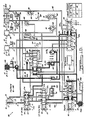
- FIG. 1D a schematic diagram of the hydraulic system 600 for controlling and operating the fluid flow throughout the transmission 100 is shown.
- the pump assembly 200, clutch assemblies 302, 304, 306, 308 and 310, torque converter assembly 110 of Figure 1A, and valves to be described herein, are connected by a plurality of internal passageways, generally indicated at 602, in or between the valve body 603, transfer plate (not shown) and transmission case 102.
- the fluid source of the transmission 100 is the fluid contained in the transmission pan (not shown) which acts as a reservoir.
- a filter 605 is attached to the lower half of a transfer plate at the inlet of the transfer plate to prevent dirt and other foreign matter from entering the hydraulic system 600.
- Another filter (not shown) is disposed in the valve body 603 at the pump pressure inlet to a pressure regulator valve 608 to protect the pressure regulator valve 608 from any loose chips and dirt in the pump hydraulic circuit.
- the pump assembly 200 is also connected by the passageways 602 to a manual valve (manual valve means) 604 which is coupled to the manually actuated shift lever or manual shaft 591.
- the manual shaft 591 is connected to the manual lever 578, its shift lever position PRNODDL being generally indicated by numeral 606.
- the pump assembly 200 is further connected by passageways 602 to a pressure regulator valve (regulator valve means) 608 and to a solenoid or fluid switch valve (switch valve means) 610.
- the passageways 602 also connect the pressure regulator 608 to a cooler or torque converter (T/C) control valve 612.
- T/C cooler or torque converter
- the passageways 602 also connect the T/C control valve 612 to a lock-up (LU) switch valve 614.
- the passageways 602 further connect the LU switch valve 614 to the torque converter 110, and they also provide a path from the torque converter 110 back to the LU switch valve 614 and to T/C control valve 612.
- a cooler 616 is connected by passageways 602 to the T/C control valve 612.
- the manual valve 604 is also connected by passageways 602 to an underdrive element or clutch apply cavity 618, an overdrive clutch apply cavity 620, reverse clutch apply cavity 622 and a two/four shift clutch apply cavity 624.
- a low/reverse clutch apply cavity 626 is connected by passageways 602 to the solenoid switch valve 610 and, in turn, to the manual valve 604.
- the clutch apply cavities 618, 620, 622, 624 and 626 are also identified in Figures 1B and 1D.
- the valves 604 and 610 are also connected by passageways 602 to a vent reservoir 628 in the manifold assembly 700 which is at a higher elevation than the sump or fluid reservoir in the transmission pan. The other valves vent to the sump as indicated by the letter "V".
- the hydraulic system 600 also includes an underdrive element or clutch solenoid-actuated valve 630, overdrive clutch solenoid-actuated valve 632, two/four shift clutch solenoid-actuated valve 634 and low/reverse clutch solenoid-actuated valve 636, which are shown in Figure 1D.
- the solenoid-actuated valves 630, 632, 634 and 636 control the fluid flow to their respective clutch apply cavities 618, 620, 624 and 626.
- the manual valve 604 controls the fluid flow to the reverse clutch apply cavity 622.
- the low/reverse clutch solenoid-actuated valve 636 includes a second or dual function of controlling fluid flow to the LU switch valve 614 during lock-up of the torque converter 110.
- the two/four clutch solenoid-actuated valve 634 also has a dual function of controlling fluid flow to the low/reverse clutch apply cavity 626 when the shift lever position 606 is reverse.
- These solenoid-actuated valves 630, 632, 634 and 636 operate in response to command or control signals from the electronic controller.
- both the underdrive clutch solenoid-actuated valve 630 and two/four shift clutch solenoid-actuated valve 634 are designed to be normally applied. This means that in the absence of electrical power, the solenoid-actuated valves 630 and 634 will allow pressure or fluid flow in the passageways 602 to be transmitted to the underdrive clutch apply cavity 618 and two/four shift clutch apply cavity 624, respectively. Hence, the underdrive clutch assembly 302 and two/four shift clutch assembly 308 will be applied, resulting in the transmission 100 operating in second gear. Likewise, the overdrive clutch solenoid-actuated valve 632 and low/reverse clutch solenoid-actuated valve 636 are designed to be normally vented.
- the hydraulic system 600 also includes accumulators 638, 640, 642 and 644 which are connected to passageways 602 before the underdrive 618, overdrive 620, two/four shift 624 and low/reverse 626 clutch apply cavities, respectively.
- the accumulators 638, 640, 642 and 644 comprise a first spring 645a, a second spring 645b and a piston 645c operating in a bore 645d in the valve body 603.
- the purpose of these accumulators 638, 640, 642 and 644 is to absorb the fluid apply pressure to help cushion the application of the underdrive 302, overdrive 304, two/four shift 308 and low/reverse 310 clutch assemblies, respectively.
- Pressure switches 646, 648 and 650 are connected to the passageways 602 which lead to the overdrive clutch apply cavity 620, the two/four shift clutch apply cavity 622 and the low/reverse clutch apply cavity 626, respectively.
- the pressure switches 646, 648 and 650 provide a digital electrical signal of zero (0) value when there is either an absence of fluid pressure or fluid pressure below a predetermined pressure, and a value of one (1) when there is fluid pressure present at or above a predetermined pressure in the passageway 602 leading to the respective clutch apply cavities 620, 624 and 626.
- suitable pressure sensors may be employed in these or other locations in the appropriate application.
- the hydraulic system 600 also includes first 652, second 654, third 656, fourth 658 and fifth 660 ball check valves in the passageways 602 leading to the low/reverse 626, underdrive 618, low/reverse 626, reverse 622 and overdrive 620 clutch apply cavities, respectively.
- the ball check valves 652, 654, 656, 658 and 660 comprise a rubber ball operating against a seat, typically formed in the valve body 603, and are used for flow control to open and close particular passageways 602. The ball is seated by pressure acting against the ball and unseated by pressure being applied on the opposite or seat side of the ball.
- the LU switch valve 614, T/C control valve 612 and pressure regulator 608 include springs 662, 664 and 666, respectively, at one end to preload these valves.
- a thermal valve 668 is also provided to regulate the fluid flow through check valve 654 at higher fluid temperatures. The thermal valve 668 closes or opens a particular passageway 602 based on the fluid temperature.
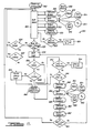
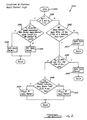
- the logic or methodology of the transmission controller 3010 is shown at 800.
- the transmission controller 3010 performs or enters a seven millisecond (7 ms.) main program or control loop.
- the methodology advances to block 804 called shift select to "orchestrate" various methods used to determine the operating mode or gear, i.e. first gear, the transmission 100 is presently in and which gear the transmission 100 should be in next, and comparing the two to each other to determine if a shift is required.
- the methodology advances to bubble 806 to calculate the speed and acceleration of the turbine 128, output gear 534 and engine crankshaft 114.
- the transmission controller 3010 receives input data from the turbine speed sensor 320 (turbine speed N t ), output speed sensor 546 (output speed N o ) and engine speed sensor (not shown) (engine speed N e ) in circle 808.
- the engine speed N e , turbine speed N t and output speed N o are calculated from the input data.
- the methodology advances to bubble 810 called the shift schedule to be described under section heading "SHIFT SCHEDULE METHOD”.
- the shift schedule bubble 810 reads or determines the shift lever position 606, PRNODDL, of the manual lever 578 by contact switch sensors (NS1, NS2) in circle 812.
- the shift schedule bubble 810 also determines the throttle angle THRT ANGLE of the engine, by an input of a potentiometer (not shown) connected to the throttle (not shown) in circle 814.
- the shift schedule bubble 810 further determines the engine temperature in circle 816.
- the shift schedule bubble 810 uses the data items such as output speed N o in circle 815 (generated by bubble 806), PRNODDL (generated by circle 812) and throttle angle (generated by circle 814) to determine the appropriate gear the transmission 100 should be placed.
- the methodology advances to bubble 818 which outputs the appropriate command signals to the solenoid-actuated valves 630, 632, 634 and 636 and properly energizes or de-energizes them based on which gear the transmission 100 is in, as determined by circle 812.
- the methodology advances to bubble 820 to execute diagnostic or monitoring routines.
- the transmission controller 3010 determines if the proper pressure switches 646, 648 and 650, previously described, are pressurized by either looking for signals from a specific pressure switch combination for the present in-gear condition of the transmission 100 or from a specific pressure switch to a non-controlling clutch during a pressure switch test to be described.
- the transmission controller 3010 also determines if the wires in the control system are not shorted or open by looking for a flyback voltage or EMF spike during a solenoid continuity test. The methodology then advances to diamond 822 and determines whether a failure has occurred. If a failure has occurred, the methodology advances to block 824 in which the transmission controller 3010 de-energizes the solenoid-actuated valves 630, 632, 634 and 636 which assume their normal positions to allow the transmission 100 to operate in second gear in the drive mode, i.e. limp-home mode previously described. If a failure has not occurred, the methodology advances to the shift select block 804. Based on the calculated speeds and shift schedule output (SSOUTP), the methodology determines if a shift is required. This process is done every 7 ms.
- SSOUTP shift schedule output
- the methodology advances to diamond 826 and determines if a shift or gear change is required. If a shift is required, the methodology advances to block 828 called the shift logic to be described herein. Otherwise, if a shift is not required, the methodology advances to diamond 830 and looks at the lock-up schedules, i.e. a plot of THAT ANGLE verses N t , etc., to determine if lock-up of the torque converter 110 is required. If lock-up is not required, the methodology returns to the beginning of the shift select block 804 again for another 7 ms. loop.
- the methodology advances to diamond 832 and determines if the torque converter 110 is presently locked-up by looking for a flag that has previously been set during full lock-up of the torque converter 110. If the torque converter 110 is presently locked-up, the methodology returns to the shift select block 804. Otherwise, the methodology advances to block 834 called partial lock-up logic or methodology, to be described under section heading "TORQUE CONVERTER LOCK-UP METHOD", for the torque converter 110.
- the shift logic block 828 uses one of twelve unique shift programs or routines.
- the shift routines are 1-2, 2-3, 2-4, 3-4 (upshifts); 4-3, 4-2, 3-2, 3-1, 2-1, (downshifts); and N-1, R-N, N-R (garage shifts) to be described herein.
- the shift logic block 828 has to identify the proper shift logic routine, and then execute it.
- the shift logic block 828 controls the solenoid-actuated valves 630, 632, 634 and 636 to shift the transmission 100 from its present gear to the next gear in a smooth manner.
- the methodology advances to diamond 836 and determines if lock-up of the torque converter 110 is required as previously described. If lock-up is required, the methodology advances to diamond 838 and determines whether the torque converter 110 is already locked-up as previously described. If the torque converter 110 is not already locked-up, the transmission controller 3010 executes the partial lock-up block 834, to be described herein.
- the partial lock-up block 834 is used to reduce slip of the torque converter 110. Slip equals N e minus N t .
- the partial lock-up block 834 instructs or causes the transmission 100 to fully lock, partially lock or fully unlock the torque converter 110. If unlock is desired, the transmission controller 3010 will hold the solenoid-actuated valve 636 in the de-energized or normally vented mode to move the LU switch valve 614 and allow fluid pressure to disengage the lock-up clutch 186. If partial lock is desired, the transmission controller 3010 will reduce slip to a low or predetermined desired value, but not completely eliminate it. The transmission controller 3010 calculates the slip by N e minus N t based on the input from the sensors previously described.
- the transmission controller 3010 compares this to a predetermined desired value of slip, e.g. 60 r.p.m., and thus, determines if the torque converter 110 is slipping too much or too little. If too much slip occurs, the transmission controller 3010 will increase the duty cycle ("ON" time) of the low/reverse clutch solenoid- actuated valve 636 and the LU switch valve 614, which will increase the pressure differential across the lock-up clutch assembly 186 and thus, decrease the slip. This technique is called "pulse-width modulation".
- the transmission controller 3010 will gradually increase the fluid pressure to the lock-up clutch 186, adding more "ON" cycle time to the solenoid-actuated valve 636 thereby increasing the "ON" cycle time at the LU switch valve 614 until maximum, resulting in zero slip.
- the methodology advances to bubble 840 to execute diagnostic or monitoring routines as previously described. Similarly, if the transmission controller 3010 determines that the torque converter 110 is already locked-up in diamond 838, the methodology advances to bubble 840 to execute diagnostic or monitoring routines as previously described. Further, once the partial lock-up block 834 is completed, the methodology advances to bubble 840 to execute diagnostic or monitoring routines as previously described.
- the methodology advances to diamond 842 and determines whether a failure has occurred as previously described. If a failure has occurred, the methodology advances to block 844 and causes the transmission 100 to default to or operate in second gear. Otherwise, if no failure occurs in diamond 842, the methodology advances to diamond 846 and determines if the time period for the diagnostic loop has expired by any suitable method such as looking at a counter. If the time has not expired, the methodology advances to bubble 840 to execute the diagnostic routines again until the time period has expired. If the time period has expired, the methodology advances to bubble 848 to calculate speeds N e , N t and N o as previously described. The methodology then advances to bubble 850 to perform another shift schedule as previously described using PRNODDL circle 852, output speed N o circle 855, THRT ANGLE circle 854, and engine temperature circle 856.
- the transmission controller 3010 slips the clutches of the multi-clutch assembly 300.
- the transmission controller 3010 has to control the pressure on applying clutches and releasing clutches in an orchestrated manner.
- the methodology advances from the shift schedule bubble 850 to bubble 858 and determines the appropriate rate of acceleration, called the "desired acceleration" (alpha desired or a*) to control the turbine 128.
- the desired acceleration may be predetermined by an equation, point/slope interpolation or any other suitable method.
- the methodology advances to bubble 860 and calculates the present acceleration (alpha t or a t ) of the turbine 128 based on turbine speed N t which tells the transmission controller 3010 how quickly the shift is happening.
- the transmission controller 3010 indirectly compares the value of desired acceleration with the calculated acceleration. This may be accomplished by placing the above values into an equation to decide the duty cycle for proportional control to be described.
- the methodology advances to bubble 862 to output the appropriate command signals to either actuate and/or deactuate (turn logically either "ON” or “OFF") the solenoid-actuated valves 630, 632, 634 and 636 for the engaging (apply) or disengaging (release) of the clutches.
- the transmission controller 3010 reduces the pressure on the applying clutch by either actuating and/or deactuating the solenoid-actuated valves 630, 632, 634 and 636 in bubble 862.
- the transmission controller 3010 increases the pressure on the applying clutch by either actuating and/or deactuating the solenoid-actuated valves 630, 632, 634 and 636 in bubble 862. If the turbine assembly 128 is accelerating at the desired acceleration level, the solenoid-actuated valves 630, 632, 634 and 636 are either actuated and/or deactuated to obtain the shift or gear change.
- the methodology advances to diamond 864.
- the methodology returns to the beginning of the control loop to the shift select block 804. If the shift or gear change is not complete, the methodology returns to the shift logic block 828 to repeat the method as previously described.
- the shift schedule method determines the appropriate gear in which the transmission 100 should be placed.
- the shift schedule method first determines the present gear of the transmission 100 by the shift lever position 606 of the manual lever 578 in circle 812 of Figure 2. Based on the shift lever position 606, the shift schedule method determines the appropriate gear in which the transmission 100 should be placed.
- the bubble 810 of Figure 2 for the shift schedule method is shown.
- the methodology enters from the shift select block 804 through bubble 900 and advances to diamond 902.
- the methodology determines whether the shift lever position (SLP) 606 of the manual lever 578 is park P or neutral N by reading a coded signal from the sensors NS1 and NS2 to be described. If SLP 606 is park or neutral, the methodology advances to block 904 and sets the new output (SSOUTP) of the shift schedule (SS) to neutral. The methodology then returns or exits through bubble 906.
- SLP shift lever position
- SS new output
- SLP 606 if SLP 606 is not park or neutral, the methodology advances to diamond 908 and determines whether SLP 606 is reverse R by the signal from the sensors NS1 and NS2. If SLP 606 is reverse, the methodology then advances to block 910 and sets shift schedule to reverse. The methodology then returns or exits through bubble 906.
- SLP 606 if SLP 606 is not reverse, the methodology advances to block 912 concludes or determines that SLP 606 is equal to overdrive OD, drive D or low L.
- the methodology then advances to block 914 and selects two adjacent lines based on the present shift schedule and the shift schedule graphs shown in Figures 4B through 14D for a SLP 606 of overdrive OD, drive D or low L.
- the methodology advances to block 916 and scans these lines using a technique called "point slope" (PSLOPE), which is a linear interpolation technique (N o on X-axis and throttle angle on Y-axis).
- PSLOPE point slope
- the methodology advances to diamond 918 and determines whether there is a new shift schedule to a coastdown shift, i.e.
- the methodology advances to block 920 and checks the gear ratios of the gear assembly 500 by performing speed calculations to avoid a "shock" from a power-plant reversal situation.
- a power-plant reversal situation or condition exists when the wheels of the vehicle drive the engine through the transmission during deceleration rather than the engine driving the transmission, in turn, driving the wheels.
- the methodology advances to diamond 922 and determines whether a power-plant reversal situation or condition exists. If a power-plant reversal condition exists, the methodology advances to block 924 and does not change the shift schedule. The methodology returns or exits through bubble 926.
- the methodology advances to block 928. Also, if a power-plant reversal condition does not exist at diamond 922, the methodology advances to block 928. At block 928, the methodology allows for a new shift schedule. The methodology then advances to block 930 and checks for diagnostic situations or conditions as previously described in conjunction with Figure 2. The methodology advances to diamond 932 and determines whether a diagnostic situation or condition exists. If a diagnostic condition does not exist, the methodology advances to block 934 and allows the shift schedule to proceed or be changed to the new shift schedule. If the diagnostic condition does exist, the methodology advances to block 936 and does not change the shift schedule. The methodology advances from blocks 934 and 936 to bubble 938 and exits or returns.
- the present invention provides fully adaptive electronic transmission controls. These adaptive controls perform their functions on real-time feedback sensor information, as is likewise performed by electronic antiskid brake controls. Additionally, the adaptive controls “learn" particular information by monitoring data such as the value for the fill time and apply rate of the applying element such as a clutch. This information is then stored in the memory of the transmission controller 3010 for future use.
- the upshift methodology uses the learned values for the fill time and apply rate (torque build-up rate) of the ON-coming or applying element such as a clutch and for the release time of the OFF-going or releasing element such as a clutch.
- Learning apply element fill time permits timing the beginning-of-fill so as to compensate for orifice size or clutch clearance variations, etc.
- Learning the apply rate and release time allows compensation for variations in orifice size, clutch capacity, solenoid response, and torque requirement (included to some extend, different engines). Although learning is restricted to the HOT mode, some temperature compensation occurs between summer and winter.
- the methodology adjusts the apply and release events so that release element slip occurs just before the apply element begins to develop torque. Slip must be allowed to occur so that the release and apply events can be identified by speed measurements.
- release time is measured as the interval between initial-element-vent and beginning-of-slip; fill time is from beginning-of-fill to end-of-bump-along; and apply rate is from end-of-bump-along to beginning-of-speedchange.
- Bump-along is a term coined to describe the bang-bang (fixed percent ON-OFF time) control period that the methodology uses to maintain a small amount of backward slip prior to the application of the apply element.
- the methodology delays either the beginning of the release vent or the beginning of apply fill so as to achieve approximately one cycle of bump-along.
- This control methodology reduces the release element pressure to the minimum that will still support the input torque reaction, thereby establishing the optimum beginning conditions for the element exchange.
- the apply rate is selected to develop the torque needed to begin speed change just as release element net-apply-pressure reaches zero.
- the duty-cycle-controlled apply rate matches the ballistic release rate of the OFF-going or releasing element.
- the purpose of the matched exchange is to minimize fight between the elements. Release time and apply rate are both learned relative to the throttle angle.
- the apply element pressure is controlled to provide the desired turbine acceleration alpha t .
- This speed change control is the heart of adaptive control since it adapts to changes in engine torque, friction coefficient, etc. and provides consistent control.
- the learned term for fill time is time remaining to nearly fill, T f .
- T f minimizes the possibility of a too aggressive element application and allows the use of a duty cycle to soften the initial application.
- T f is actually calculated from the learned clutch fill volume, V f . This term is stored in cubic inches so that different flow rates may be used to calculate T f . This allows the same learned volume to be used for different shifts which may have a different line pressure.
- the program or methodology continually tracks the fluid volume needed to apply each element.
- T r time to nearly release
- K S is the learned multiplier for that individual package. Since T s varies with THR (i.e. engine torque), a multiplier provides the best data match for the variables being accommodated. The .063 seconds, together with the T f differential, provides a margin to ensure that fight is minimized.
- a duty cycle may then be initialized and updated to provide proportional control for the speed change.
- the primary element DC acceleration or proportional control (DC alpha , i.e. variable percent ON or OFF time) initialization level is calculated for N e and N t , the torque converter characteristics, and the element capacity; each DC alpha update is based on an anticipated turbine acceleration (alpha t ) error.
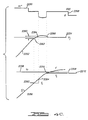
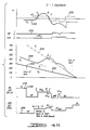
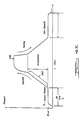
- a shift tape of the transmission characteristics for a third to first (3-1) kickdown shift is generally shown at 2200.
- Curve 2202 represents throttle angle.
- engine speed N e shown in curve 2204 also increases.
- the release element is released as shown in curve 2206 to drop its torque capacity.
- the overdrive clutch 304 is released at the start of the shift.
- the fluid pressure of the overdrive clutch 304 vents down.
- the present invention limits the rate at which the turbine 128 accelerates. This is accomplished by calculating and comparing an instantaneous turbine acceleration (alpha t ) shown in curve 2212 against a desired acceleration (alpha desired or a*) level shown in curve 2214. Once the speed change begins at 2210, the controller 3010 attempts to match alpha t approximately equal with alpha desired .
- the release element When alpha t exceeds alpha desired , the release element is reapplied to control the rate at which the turbine 128 accelerates.
- the release element is reapplied under duty cycle acceleration or proportional control (DC alpha ) to provide a controlled slope of speed change on the turbine 128.
- curve 2212 of alpha t crosses curve 2214 of alpha desired at point 2216.
- the overdrive clutch 304 is reapplied by duty cycling the solenoid-actuated valve 632 as shown by part 2218 of curve 2206.
- the kickdown methodology adaptively applies the applying element (low/reverse clutch 310) as shown by curve 2220 based on the remaining turbine speed change which has to occur.
- the methodology compares the actual turbine speed N t to a target speed N j (for a 3-1 shift, first gear ratio of first gear N j ). Because the speed change is made at a known rate (because controlling release element at that rate), the methodology can predict how much time remains to fill the applying element.
- the methodology attempts to get the applying element filled after achieving the target speed N j for a predetermined time period such as 120 ms, which region 2224 of curve 2214 is called "hold-speed".
- N t exceeds the target speed N j at point 2226, i.e. enters the hold-speed region 2224, alpha desired is lowered again to a negative value at point 2228 on curve 2214 so that the release element will prevent further increases in N t .
- DC bb is again used for improved response before reentering DC alpha control.
- the release element hold-speed continues until the apply element is filled, begins to develop torque, and pulls N t down to the target level, N j .
- the methodology then turns OFF the release element when N t equals N j .
- the methodology tracks element volume during solenoid OFF and ON times there is little error that can develop if alpha t is lower than alpha desired .
- the methodology simply turns OFF the element and waits for N t to catch up to the projected level. If alpha t is higher than alpha desired , the controls have no means to catch up, but since the initial release element vent time and the alpha desired "feather" control cause alpha t to be lower than alpha desired normal, there is no opportunity for significant "fall-behind” error to develop.
- the present invention utilizes "adaptive" kickdown start logic which is based on a "learned" fill volume of the applying element.
- curve 2232 represents the kickdown start value S.
- t f is the time needed to fill the applying element to the level that will provide the correct amount of bump-along time or kickdown hold-speed time (i.e. 120ms).
- N t > N j - S the apply element is turned ON which reduces S because the apply element is filling. If N j - S > N t (i.e. N t falls below S), the apply element is turned OFF. This results in an irregular or variable DC on the apply element.
- the transmission controller 3010 compares N t to S. If N t is greater than N j minus S, the methodology instructs the transmission controller 3010 to turn ON the applying element to reduce S to zero. Hence, the methodology drives S to equal zero just as N t crosses or equals N j at point 2226. This allows 120ms. of time remaining to complete the fill (hold-speed), resulting in better shift quality. Otherwise, the shift quality would be "jerky" if the apply element were applied just as N t crossed N j .
- the equation for the turbine torque (T t ) is derived by the graph of turbine torque T t divided by engine speed N e squared (which is the same as impeller speed squared) versus speed ratio of turbine speed N t divided by engine speed N e which is curve 2280.
- Figure 4B is based on the characteristics of a particular model of torque converter. This can be used at any time that the lockup clutch is disengaged to calculate an input torque to the transmission 100. For a particular element involved (knowing what its capacity is), the transmission controller 3010 can calculate the DC necessary to provide the appropriate level of element torque (i.e. initial DC). After the initial percent ON time for the DC, the DC adaptively adjusts to maintain alpha desired .
- initial DC the appropriate level of element torque
- the only learned quantity used for making downshifts is the fill time of the applying element or clutch.
- the element volumes are actually learned and stored. Fill times are calculated by using the learned element volume and an appropriate flow rate from a look-up table and graph of flow rate characteristics for each element for example.
- the learned volume information for a given element is shared between different shifts both upshifts and downshifts.
- the flow rate used accounts for the individual hydraulic flow rates and compensates for line pressure differences which exist between different shifts (i.e. for element fill rates, not vent rates).
- a learned fill rate is used for coastdown shifts only. This fill rate is set at the regulated line pressure level with each start-up (because with cold fluid, the pump 200 will maintain the regulated pressure) and it will learn any reduction in the fill rate with each subsequent shift.
- the learn logic for kickdown shifts tracts the instantaneous volume of the apply element and compares that value with the current fill volume such that the apply element is completely filled at the end of the hold-speed region.
- curve 2250 represents a desired acceleration (a*) of the turbine 128.
- Curve 2252 represents turbine speed N t and curve 2254 represents a target speed (N j ) of the turbine 128.
- Curve 2256 represents an instantaneous fill volume (V I ) of the apply element and curve 2258 represents the current fill volume (V f ) of the apply element.
- N t approaches N j
- N t comes within a predetermined range 2260 of N j .
- the learned volume (V L ) of the apply element is latched at that volume of the instantaneous fill volume (V I ).
- the transmission controller 3010 takes a step out of current fill volume (V f ) which is a percentage of the difference between V f and V L at point 2266.
- the fill volume (V f ) of the apply element is also "learned" and adaptively adjusted based on bump-along (i.e. element slip). As illustrated in Figure 4D, a shift tape of the transmission characteristics is shown for a first to second (1-2) upshift.
- Curve 2270 represents the stored or previously learned current fill volume (V f ) of the apply element.
- Curve 2272 represents the instantaneous volume (V I ) of the apply element (i.e. two/four shift clutch 308).
- Curve 2274 represents the learned volume (V L ).
- V L the learned volume (V L ) is set equal to the instantaneous fill volume (V I ) whenever (t f > 0) or (t f ] 0 and N f > N j + 30).
- V L tracts V I until point 2274 because t f was greater than 0.
- t f equals zero and V L stops tracking V and is set equal to the value of V I at point 2276.
- the apply element is filling in the hold-speed region. If N t is greater than N i plus a predetermined value such as 30 (i.e. slip occurs), called bump-along, V L is updated to the value of V I at point 2278.
- V L again tracks V I until N t is not greater than N i plus the predetermined value at point 2280.
- V L is set equal to the value of V I and stops tracking. This methodology is repeated whenever N t is greater than N i plus the predetermined value.
- the transmission controller 3010 compares V L to V f . If V L is greater than V f , as shown in Figure 4D, V f is adjusted or increased a percentage of difference between V L and V f . If V L equals V f , no adjustment is made. Otherwise, if V L is less than V f , V f is decreased.
- a flow chart of the learn methodology is shown.
- the methodology advances to block 2292.
- the methodology intercepts or determines the time to bump-along, time to speed change, and instantaneous volume during bump-along of the element.
- the methodology then advances to diamond 2294 and determines whether the shift has been completed. If no, the methodology loops back to block 2292. If the shift has been completed, the methodology advances to block 2296 and learns the fill volume if the conditions are valid, learns K s (release time multiplier), if conditions are valid and learns DC t (adjustment) if conditions are valid. From block 2186, the methodology returns.
- the shift schedule (bubble 810 of Figure 2) has logic which compares engine speed N e and target speed N j and delays any coastdown shift that would go from power-ON to power-OFF since these shifts involve crossing drivetrain backlash and may result in a "clunk”.
- the 3-1 and 2-1 shifts are power-ON coastdowns (a 3-2 power-ON coastdown shift is not made); the 4-3 is typically a power-OFF shift (it may be power-ON if the shift is inhibited by the below "backlash" logic).
- a graph of speed (r.p.m.) versus time is shown at 2300 for an adaptive fourth to third (4-3) gear coastdown shift.
- Curve 2302 represents the output speed N o or target speed N j for third gear.
- Curve 2302 represents the engine speed N e .
- Curve 2306 represents turbine speed N t .
- N e will be less than N j . If a shift is scheduled by the transmission controller 3010 when N e is less than N j , the start of the 4-3 shift will occur at point 2308. As the shift occurs, N t will increase and cross over N e , as indicated by point 2310, from positive to negative torque, resulting in a "clunk" of the drivetrain.
- the present invention provides the feature of delaying or inhibiting the start of the shift by the transmission controller 3010 until N e is at least equal to or greater than N j , as indicated by point 2312. This is accomplished by delaying the actuation and/or deactuation (i.e. turning ON and/or OFF) of the appropriate solenoid-actuated valves. By inhibiting the shift, N t will remain less than N e during the entire shift, resulting in only positive torque and preventing any "clunk" of the drivetrain.
- a phase plane graph of turbine acceleration (alpha t ) versus turbine speed N t minus target N j (first gear) for a second to first (2-1) gear coastdown shift is shown at 2320.
- the solid line curve 2322 represents the desired acceleration (alpha desired or a*) which is a function of slip.
- Alpha desired goes to a negative value in the hold-speed region of the downshift.
- the present invention provides methodology for controlling alpha t at point 2324 which is approximately 25 r.p.m. This is accomplished by using proportional control (DC alpha or DCa). DC alpha is used during coastdown shifts because real tight control hold-speed is needed and is lacking otherwise.
- proportional control DC alpha or DCa
- curve 2326 represents the vent release element (VRE) which is identified during a coastdown shift by alpha desired minus a predetermined value such as 1000.
- VRE vent release element
- the applying element may be ON, or it is desired to vent the release element faster than normal DC alpha would (rather than backing off the release element's duty cycle by DC alpha , which would eventually release the element).
- the release element is turned OFF. This would result in actual alpha t coming back above the VRE curve 2326 if the apply element was not ON.
- the methodology would instruct the transmission controller 3010 to turn the release element ON. If the apply element was ON, alpha t would not come back above the VRE curve 2326.
- curve 2328 represents hold the apply pressure (HAP).
- HAP is used where there is too much negative alpha t .
- HAP is used where alpha t is less than a predetermined value such as -1700.
- HAP prevents the apply element from applying hard quickly by duty cycling the apply element to maintain it at a predetermined pressure. This prevents the apply element from building up torque any faster in the hold-speed region, causing alpha t to come back above the HAP curve 2328.
- a plot of actual turbine acceleration (alpha t ) represented by curve 2330 and desired acceleration (alpha desired or a * ) represented by curve 2332 is shown for a second to first (2-1) gear coastdown shift.
- a logic curve 2234 represents VRE and logic curve 2236 represents HAP.
- a plot of turbine speed N t represented by curve 2338, target speed N j represented by curve 2340, and output speed N o represented by curve 2342 is shown from the start to the end of the second to first gear coastdown shift.
- Logic curves 2344 and 2346 show the element logic for the release element (two/four shift clutch 308) and the apply element (low/reverse clutch 310), respectively.
- the release element is ON until the start of shift at point 2348. At that time, the methodology turns the release element OFF. Simultaneously, the apply element which has been previously OFF is maintained OFF. Also, curve 2338 of N t is less than curve 2340 of N j .
- alpha t starts to rise or increase.
- the release element is turned ON or reapplied using duty cycle bang-bang (DC bb ).
- DC bb is used until alpha t again crosses alpha desired at point B.
- N t crosses N j at point B.
- the release element switches from DC bb to proportional control (DC alpha or DCa).
- the apply element comes on before point B to be ready at the right time into hold-speed region (starts at point C).
- alpha desired enters the hold-speed region.
- VRE is applied as previously described.
- alpha t is below the HAP value, HAP will be applied as previously described.
- N t is matched to N j and alpha t is matched to alpha desired at the end of the shift by using DC bb , DC alpha , VRE and/or HAP.
- the methodology for the release element used during a coastdown or kickdown shift is generally shown at 2400.
- the methodology enters through bubble 2402 and advances to diamond 2404.
- the methodology determines whether the conditions are present Indicating that the apply element is applying. In other words, are conditions present for VRE (i.e. THR ⁇ 5 and alpha t ⁇ alpha desired - 1000). If that criteria is true, the methodology advances to block 2406 and vents the release element (applies VRE). The methodology then returns. If that criteria is not true, the methodology advances to block 2408 and establishes the phase of the shift: phase 1 equals the start; phase 2 equals the feather start (reduction in desired acceleration); and phase 3 equals target speed (hold-speed).
- the methodology then advances to block 2410 and performs a pre-DC alpha flag check by setting the flag with slip and alpha t is HI or the release element is below fill volume, and clearing the flag with a change in the phase of the shift.
- the methodology then advances to block 2412 and performs a duty cycle alpha flag check.
- the methodology sets the DC alpha flag when the pre-DC alpha flag has been set and alpha is LOW (i.e. alpha t , high-to-low crossover) and it cleared with the change in phase of the shift.
- the methodology then advances to diamond 2414 and determines whether the DC alpha flag has been set.
- DC alpha control is when the total period is fixed and the ON and OFF time is calculated and adjusted (i.e. variable ON and OFF time). The methodology then returns. If the flag has not been set, the methodology advances to diamond 2418 and determines whether alpha t is HI. If that criteria is true, the methodology advances to block 2418 and performs DC bang-bang control or DC bb on the release element and returns. DC bb control is when the total period is fixed and the ON and OFF time is fixed (e.g. at 60% ON). If that criteria is not true, the methodology advances to block 2420 and vents the release element and returns.
- the methodology for the apply element is generally shown at 2450 for a coastdown or kickdown shift.
- the methodology enters through bubble 2452 and advances to diamond 2454.
- the methodology determines whether the phase of the shift is equal to one or two and N t is less than N j . If any of this criteria is true, the methodology advances to diamond 2456 and determines whether N t is above the speed associated with the correct apply timing (i.e. will element be late). In other words, the methodology determines whether N t is greater than S (kickdown start valve previously described). If that criteria is true, the methodology advances to block 2458 and applies the apply element and returns. If that criteria is not true, the methodology advances to block 2460 and vents the apply element and returns.
- the methodology advances to diamond 2462 and determines whether the apply element will apply within 120 ms if run at a predetermined duty cycle by looking at the fill volume (V f ). If that criteria is not true, the methodology advances to block 2464 and applies the apply element and returns. If that criteria is true, the methodology advances to diamond 2466 and determines whether vehicle speed or N o is greater than a predetermined speed such as 8 mph and less than 300 r.p.m. of run away for the turbine 128. If that criteria is true, the methodology advances to block 2468 and applies the apply element and returns.
- the methodology advances to diamond 2468 and determines whether conditions are present indicating apply element should "hold" (for a coastdown, alpha t very negative). In other words, the methodology determines whether the conditions are present to apply HAP (i.e. THR ⁇ 5 and a t ⁇ -1700). If that criteria is true, the methodology advances to block 2470 and performs DC HAP on the apply element and returns. If that criteria is not true, the methodology advances to block 2472 and performs DC alpha2 (secondary element DC acceleration control) on the apply element and returns.
- DC alpha2 secondary element DC acceleration control
- Another feature of the present invention used during a coastdown shift is a methodology called "wait-for-slip".
- the release element is vented.
- slip i.e. N t ] N j
- the methodology controls the release element at a low limit percent ON for its DC alpha .
- the methodology attempts to keep the release element from further venting because the release element may be needed to apply again. Once, the above conditions are no longer present, the release element continues to vent.
- the hydraulic system 600 includes accumulators 630, 640, 642, 644 for the clutch assemblies 302, 304, 308 and 310, respectively.
- the accumulators provide mechanical cushion so that extreme changes in pressure are not realized as the solenoid-actuated valves are turned ON or OFF. These accumulators help reduce the axial length of the transmission 100 and give more flexibility to the hydraulic system. This is advantageous over prior systems which used large cushion springs built in the clutch packs, increasing the axial length of the transmission.
- a curve 2480 of pressure versus time for applying and venting (releasing) of an element or clutch is shown.
- the accumulator control zone represented by part 2482 of the curve 2480, provides compliance or softness so that it takes time to develop a large change in pressure. Otherwise, if no accumulator was used, the slope of this part of the curve would be steeper and a small change in ON time would result in a large change in pressure, making torque capacity and shift quality unbearable.
- control is performed in the accumulator control zone to prevent large excursions in the output torque (T o ) which would create jerkiness or harshness in shift quality.
- T o the output torque
- turning the release element ON during slip or bump-along without an accumulator would produce a steeper slope in the output torque, resulting in an inability to limit slip without harsh control.
- the learned term for apply rate is torque phase duty cycle, DC t .
- the purpose of the torque phase duty cycle is to make the hand-off smooth between the release element letting go of torque and the apply element taking over torque. This is accomplished by timing the apply element to have sufficient capacity to start the speed change just as the release element capacity reaches zero. In other words, the methodology attempts to build-up apply element torque capacity to match torque fall-off capacity of the release element.
- the torque phase duty cycle is adaptively adjusted to match torque build-up of the apply element to torque fall-off of the release element according to the following equation:
- the above equation is based on a table value, DC tt or nominal DC t values (fixed % ON time) based on throttle angle, plus a learned adjustment, DC ta . Since the intent is to have the speed change begin as the release element net-apply-pressure reaches zero, the methodology selects a DC t which will achieve the start of speed change at an interval after the start of venting of the release clutch. This interval is equal to the learned time to release at zero degrees throttle angle plus an allowance for one bump-along cycle. The transmission controller 3010 does this by achieving and maintaining t f equal to zero until slip occurs, then DC t is allowed to proceed.
- curve 2500 represents the logic state of the release element.
- Curve 2502 represents slip in the transmission 100.
- the release element is turned OFF or starts to vent.
- Curve 2508 represents the logic state of the apply element.
- the apply element is initially turned OFF or vented.
- t f is equal to zero and DC t starts for the apply element.
- the slope of DC t is tailored so that it matches the build-up in apply element torque capacity. For throttle angles greater than 10 the apply element is given a 10% boost in its duty cycle so that the actual turbine acceleration (alpha t or a t ) will achieve the desired acceleration (alpha desired or a*).
- curve 2512 represents the desired acceleration (alpha desired ) and curve 2514 represents the actual turbine acceleration (alpha t ).
- the speed change begins.
- Alpha t is greater than alpha desired . Therefore, DC ta adds 10% boost in ON time to DC t for the apply element such that alpha t will be momentarily equal to alpha desired at or near the end of DC t .
- DC ta is the learned adjustment to DC t .
- DC ta is used so that the start of the speed change from the initial release occurs within a predetermined time period called time to start speed change (t n ). This time is when it is desired to have the speed change begin because the release element pressure will have decayed down to the fill pressure such that no torque capacity is on the element. Otherwise, if the speed change begins earlier or prior to this time, fight will occur because both the apply and release element have capacity.
- DC ta DC ta + 1.2%, with t n > t *a + .028 DC ta - 1.2%, with t n ⁇ t *a + .028
- t *a is an adjusted value of t * (a predetermined table value) based on a learned value of K s .
- K s is used to predict where the first cycle of bump-along occurs because of changes in temperature.
- K s is used to adjust t * based on temperature so that start of DC t for the apply element occurs just prior to the first bump-along cycle.
- a delta term is used when the transmission system has not learned out properly the above variables. If t * is less than the start of speed change at point 2506 on curve 2502, the % ON time for DC t is increased or incremented until the start of speed change begins at the end of t *. Thus, the delta term provides added protection by reacting immediately.
- Curve 2502 represents the logic state of the apply element and curve 2504 represents the logic state of the release element.
- Curve 2506 represents the desired acceleration (alpha desired ) and curve 2508 represents the actual turbine acceleration (alpha t ).
- Curve 2510 represents the pressure of low/reverse element and curve 2512 represents the pressure of the reverse element.
- the low/reverse element When the manual valve 604 is shifted to reverse R, the low/reverse element starts to vent.
- the low/reverse clutch solenoid-actuated valve 636 is turned OFF as indicated by point 2514 on curve 2502.
- the pressure in the low/reverse element starts to decrease or decay as shown by part 2516 of curve 2510.
- the reverse element is filling and the pressure starts to increase as shown by part 2518 of curve 2512.
- the pressure in the low/reverse element has decayed to a fairly low level as indicated by point 2520 on curve 2510, the low/reverse element is reapplied under DC control at point 2520 on curve 2504.
- the adaptive control system 3000 includes transmission controller 3010 which is capable of both receiving signals from an engine controller 3020 and transmitting signals to this engine controller 3020. While the transmission controller 3010 may be readily adapted to operate without an electronic engine controller, the transmission controller 3010 according to the present embodiment takes advantage of the fact that most automobiles today include a digital or computer based engine controller which receives and processes signals from numerous sensors. For example, Figure 5 shows that both the transmission controller 3010 and the engine controller 3020 receive an input signal indicative of the temperature of the engine (e.g., the coolant temperature).
- exemplary input signals shared by these controllers include one or more signals from the ignition switch, a battery voltage level signal, and a signal from the distributor or other firing angle control mechanism.
- this controller will process such signals and transmit appropriate control or command signals to various components of the engine.
- Typical computer based engine controllers will also generate and transmit advisory signals to a diagnostic alert panel in the passenger compartment to provide a visual and/or auditory indication of particular engine conditions.
- the transmission controller 3010 includes the capability of communicating with existing engine controllers. For example, it may be advisable for the transmission controller 3010 to send signals to the engine controller 3020, such as a signal indicating that the transmission 100 is about to shift gears. As will be appreciated from the description below, the transmission controller 3010 is preferably provided with a serial communications interface to permit serial data transfers to be made between the transmission controller 3010 and the engine controller 3020. Additionally, the transmission controller 3010 may also provide diagnostic alert capabilities, such as transmitting suitable advisory signals to the vehicle operator (e.g., "check transmission").
- a throttle sensor 3030 may be any suitable sensor which will give an indication of the power demand placed upon the engine by the vehicle operator, such as a transducer which will indicate the present position of the throttle.
- the brake switch 3040 may be any suitable sensor which will give an indication of the application of the vehicle brake by the operator, such as a contact switch actuated by the movement of the brake pedal in the vehicle.
- the transmission controller 3010 includes suitable interface circuits for receiving signals from the throttle sensor 3030 and the brake switch 3040. Further examples of information shared between the controllers are signals concerning vehicle type, engine type, manifold absolute pressure (MAP) and load.
- MAP manifold absolute pressure
- One of the primary functions of the transmission controller 3010 is to generate command or control signals for transmission 100 to the solenoid-actuated valves 630, 632, 634, 636 contained in the hydraulic system 600 ( Figure 1D) of the transmission 100.
- these solenoid-actuated valves are lumped into a solenoid block 3050 which is contained within a dashed block labeled "Transmission”.
- This Transmission block represents a suitable transmission structure which will operate in conjunction with the transmission controller 3010, such as the transmission 100 described above.
- the solenoid block 3050 would comprise the solenoid-actuated valves 630, 632, 634 and 636.
- the hydraulic controls block 3060 would comprise other valves contained in the hydraulic system 600, such as the pressure regulator valve 608, the manual valve 604, the T/C control valve 612 and so forth, as described above.
- the friction elements gear box block 3070 would comprise the multi-clutch assembly 300 and the gear assembly 500 as described above.
- the adaptive control system 3000 according to the present invention may be used in conjunction with other suitable transmission structures in the appropriate application.
- Figure 5 also illustrates that the Transmission block includes a PRNODDL sensor block 3080 which is responsive to a gear shift lever that is under operator control.
- the PRNODDL sensor block 3080 may be comprised of one or more suitable sensors which are capable of providing an indication to the transmission controller 3010 of the transmission operating mode selected through the manual actuation of the gear shift lever.
- Two contact switch sensors NS1 and NS2 are mounted to the transmission case 102.
- the sensors NS1 and NS2 are mounted in proximity to the manual lever 578 in order to permit a spring loaded pin of these sensors to engage and follow the peripheral track of a cap member 578a of the manual lever 578.
- the transmission controller 3010 receives input signals from the PRNODDL sensor block 3080, as well as produces output signals to a PRNODDL indicator contained in the passenger compartment.
- This PRNODDL indicator may, for example, be a suitable light source or other appropriate indicator for providing the operator with a visual indication of the operating mode which has been selected.
- Figure 5 also indicates that a pressure switch block 3090 is connected to the hydraulic controls block 3060.
- the pressure switch block 3090 would comprise the pressure switches 646, 648 and 650 ( Figure 1D).
- each of these pressure switches is adapted to provide a signal indicative of a predetermined pressure level in the corresponding passageways leading to selected friction elements.
- each of these pressure switches provide a digital input signal to the transmission controller 3010 which will indicate whether or not this pressure level has been reached.
- the Transmission block includes a speed sensors block 3100 which is connected to the friction elements gear box 3070.
- the speed sensors block 3100 comprises the input or turbine speed sensor 320 and the output speed sensor 546 which are both mounted to the transmission case 102.
- other suitable speed sensor means may be provided either within or outside of the transmission case 102 in order to provide the desired input or turbine and output speed signals to the transmission controller 3010.
- the speed sensors block 3100 may also include a suitable engine speed sensor (e.g., hall effect device). However, if the engine controller 3020 is already receiving such a speed signal, then this signal could be shared with the transmission controller 3010 to avoid unnecessary duplication.
- the first block is the serial communication interface 3200 which has as its function to provide a serial communications link with the engine controller 3020.
- This serial communication interface 3200 could also be used to provide a serial communication link with other appropriate microcomputer-based controllers in the vehicle. It should also be understood that a parallel communication could also be used in the appropriate applications.
- the serial communications interface 3200 utilizes the multiplexing protocol and interface technology of the Chrysler Collision Detection ("C
- D Chrysler Collision Detection
- This technology is described in the co-assigned U.S. Patent No. 4,706,082, entitled “Serial Data Bus For Intermodule Data Communications,” which issued on November 10, 1987; and U.S. Patent No. 4,719,458, entitled “Method Of Data Arbitration And Collision Detection In A Data Bus,” which issued on January 12, 1988; and U.S. Patent No. 4,739,323, entitled “Serial Data Bus For Serial Communication Interface (SCI), Serial Peripheral Interface (SPI) and Buffered SPI Modes of Operation,” which issued on April 19, 1988; and U.S.
- SCI Serial Communication Interface
- SPI Serial Peripheral Interface
- serial communications interface 3200 Another function for the serial communications interface 3200 is to provide a diagnostic interface with the transmission controller 3010 so that service information can be provided to a technician as a troubleshooting or maintenance aid. Still another function of the serial communications interface 3200 is to provide a convenient data or program access route for in-plant testing of the transmission controller 3010 during the manufacturing process.
- the transmission controller 3010 also includes several other interface circuits which are used to receive and condition input signals from the various sensors identified above.
- the transmission controller 3010 includes a block 3210 which contains the interface circuits used to receive signals from the speed sensors 3100 and the throttle sensor 3030.
- the transmission input speed signal represents the turbine speed N t of the torque converter 110, while the output speed signal represents the output speed N o of the vehicle.
- both of these signals are generated by variable reluctance pick-ups (e.g., speed sensors 320 and 526).
- the engine speed is also sensed by a suitable sensor, such as a hall effect pick-up in the distributor of the engine. This technology is described in co-assigned U.S. Patent No. 4,602,603, entitled "Ignition Distributor-Hall Effect Sensor Switching System and Method," which issued on July 29, 1986.
- block 3210 The function of block 3210 is to provide input signal conditioning, filtering and conversion of the speed sensor signals to digital logic levels.
- block 3210 also includes an interface circuit for the throttle position sensor 3030. Once this signal is properly conditioned, this information may be shared with the engine controller 3020.
- the throttle position sensor 3030 will give an indication as to which angular position the throttle blade (means) is in within the throttle body.
- the throttle position sensor signal is conditioned and fed through a unity gain differential amplifier to provide isolation as will be described below.
- the transmission controller 3010 also includes blocks 3220 and 3230 which represents the interface circuits used to receive various input signals related to the engine ignition and PRNODDL condition.
- the ignition related signals include a signal J2, and a signal S2.
- the signals related to the PRNODDL condition include the "neutral start” signal NS1, and “auxiliary neutral start” signal NS2, a "first reverse light” signal RL1 and a “second reverse light” signal RL2.
- the control methodology is responsive to the condition that these ignition switch voltage signals are in. The reason for this is that it is appropriate to hold the transmission controller 3010 in certain predetermined conditions depending on the position of the ignition switch and/or the neutral contact switch sensor NS1 and/or the auxiliary contact switch sensor NS2.
- the signal J2 represents the ignition voltage during the run and crank positions, and this signal will generally be either at a zero voltage level or at the battery voltage level.
- the signal S2 represents the voltage in the crank position only and is used to provide the necessary voltage for the starter relay coil of the engine. To determine when the transmission 100 is in a crank condition the NS1 or neutral start switch signal is sensed along with the S2 signal to hold the transmission controller 3010 in a reset condition during cranking due to the possibility that the battery voltage may drop below level required for proper controller operation.
- the PRNODDL condition switches provide input signals from the contact switch sensor NS1, the auxiliary contact switch sensor NS2, the first reverse light RL1 and the second reverse light RL2.
- the PRNODDL switch block 3230 controls the switching of the reverse lights which are connected in series.
- the signals RL1 and RL2 indicate a reverse condition electrical current from the ignition switch J2 is fed through a relay coil which interconnects the reverse lights to battery voltage via the relay contacts thus turning on the backup lights on the vehicle.
- the PRNODDL switch block also acts in combination with the two contact switch sensors NS1 and NS2 to determine the shift lever position, as discussed above.
- the transmission controller 3010 includes a pressure switch block 3240 which represents the interface circuit used for receiving and conditioning the pressure level signals from the pressure switches 3090.
- Each of the pressure switches provide a digital level signal which is either at a zero or battery voltage level depending upon whether or not a predetermined pressure level has been reached.
- the pressure switches are used in conjunction with the low/reverse, overdrive and two/four shift (kickdown) clutch assemblies, and generally comprise grounding switches located in the manifold assembly 700.
- the pressure switch interface circuit 3240 provides input signal conditioning, i.e. filtering and buffering for these signals. For example, pull up resistors located in the manifold assembly 700 to provide battery voltage when pressure switch is open are contained in block 3090.
- the state of each of the pressure switch signals is transmitted to the transmission controller 3010 to provide feedback information for use in both monitoring clutch operation and as an input to the learning logic and methodology described herein.
- the heart of the transmission controller 3010 is contained in the micro core block 3250.
- the micro core 3250 includes an eight-bit microcomputer unit (MCU), a memory chip for storing the application or operating program used by the MCU, and an interface chip for addressing and routing signals on the various lines used in the micro core bus structure.
- MCU microcomputer unit
- the interface chip for addressing and routing signals on the various lines used in the micro core bus structure.
- several of the signals received from the controller's interface circuits are connected to the interface chip, which will then place these signals on the data bus when the chip is properly addressed by the MCU.
- the transmission controller 3010 also includes a watchdog/reset block 3260 which provides several circuit functions in conjunction with the micro core 3250.
- the watchdog/reset circuits 3260 will control the initial start up of the MCU, watch to see if the MCU is properly functioning, cause a reset of the MCU in response to certain regulator voltage conditions, and provide a frequency divider for the speed signals.
- the watchdog/reset circuits 3260 also provide an output to a relay driver block 3270 which is used to disconnect or turn off electrical power to the solenoid-actuated valves 630, 632, 634 and 636 in the solenoid block 3050 shown in Figure 5 under predetermined conditions.
- the solenoid driver block includes a separate driver circuit for the solenoid-actuated valves 630, 632, 634 and 636 contained in the solenoid block 3050 shown in Figure 5. These driver circuits generate the electrical current necessary to operate the solenoid- actuated valves 630, 632, 634 and 636 in response to the control signals generated by the MCU.
- the solenoid driver block 3280 also includes spike monitor circuits which verify the operation of the solenoid driver circuits by detecting the presence of an inductive spike which occurs when the solenoid coil is de-energized.
- the transmission controller 3010 also includes a regulator block 3290 and a test mode block 3300.
- the regulator block 3290 is used to advise the watchdog/reset circuit 3260 of predetermined conditions relating to the operation of the regulator, such as a low battery voltage condition, a high battery voltage condition, an overload condition, or an over temperature condition in the regulator. It is a dual regulator and includes a 5V, switched output.
- the test mode block 3300 is used to permit a test mode program to be downloaded into the RAM memory of the MCU for testing the transmission system.
- Figures 7A-7G a schematic diagram of the transmission controller 3010 is shown.
- Each of the Figures 7A-7G generally correspond to one of the circuit blocks shown in Figure 6.
- Figure 7A illustrates the serial communication interface 3200 which provides a serial communication link between the transmission controller 3010 and the engine controller 3020.
- Figure 7B illustrates the MCU chip Z138 and the interface chip Z135 which form part of the micro core 3250.
- Figure 7C illustrates the EPROM chip Z141 and its associated circuitry.
- Figure 7C illustrates a watchdog/reset chip Z127 and associated circuitry, which together correspond to the watchdog/reset circuit 3260.
- Figure 7D illustrates the speed and throttle input interface circuits 3210.
- Figure 7E illustrates the PRNODDL interface circuits 3230 and part of the ignition switch interface circuits 3220.
- Figure 7F illustrates the regulator circuit 3290 and the relay driver circuits 3270.
- Figure 7G illustrates the solenoid driver circuits 3280.
- FIG. 7A a schematic diagram of the serial communications interface 3200 is shown.
- This communications interface actually provides for two serial communication channels for the transmission controller 3010.
- the first serial communication channel 3201 is based upon the Chrysler Collision Detection (C
- D Chrysler Collision Detection
- This technology is embodied in the communications chip Z14 which provides the intelligence to know when it has sent a message out onto a serial data bus and whether or not it has won access to the bus.
- This bus comprises the two conductors labeled "(C
- this serial communications bus comprises a double ended or differential signal transmission link with the engine controller 3020 (or any other appropriate controller in the vehicle which is connected to the bus structure).
- the communications chip Z14 receives signals transmitted from the microcomputer chip Z138 (shown in Figure 7B) via its connection to the "PD3" port of the microcomputer. Similarly, signals are transmitted from the communications chip Z14 to the microcomputer chip Z138 via the "PD2" port.
- the communications chip Z14 is provided with a clock signal "E**" which is derived from the MCU chip's Z138 system clock, namely the "E” Clock. As shown in Figure 7C, two NAND gates Z195 are connected in series to double buffer and double invert the E clock signal. Signal transmissions from the MCU chip Z138 are initiated by the MCU chip Z138 which pulls down a "Control" line of communications chip Z14 via a command signal transmitted from the "PD5" port. However, the communications chip Z14 will actually control the transfer of data from the MCU chip Z138 by providing a "SCLK” clock signal to the MCU's "PD4" port, which will clock the data in and out of the MCU chip.
- the communications chip Z14 is turned off when the transmission controller 3010 is in a stop mode, such as after the ignition key is turned off.
- the communications chip Z14 is turned off through the "SW/5V" power supply.
- the SW/5V voltage level is derived from a dual regulator Z215 contained in the regulator circuit 3290 shown in Figure 7F. Specifically, the SW/5V supply is switched on or enabled by the MCU Z138 in response to the ignition switch.
- FIG. 7A also illustrates the second serial communications channel which is generally designated by the reference numeral 3202.
- the serial communications channel 3202 is generally comprised of a transmit line labeled "SCI-XMT" and a receive line labeled "SCI-REC". Each of these transmit and receive lines include an RC filter and a buffering inverter Z15.
- the transmit line SCI-XMT is connected to the "PD1" port of the microcomputer chip Z138, while the receive line SCI-REC is connected to the "PD0 ⁇ " port of the microcomputer chip.
- This second serial communications channel may be used for example to download appropriate test programs into the microcomputer chip Z138, such as for end of line testing at the manufacturing facility.
- the SCI-REC receive line is used in conjunction with the test mode to transmit a signal to the microcomputer chip Z138 which will cause a ROM resident boot load program inside the microcomputer chip to control the receipt and initial execution of the test programs.
- the micro core 3250 for the transmission controller 3010 generally comprises the microcomputer 3251 (chip Z138), the interface 3252 (chip Z135), and the memory 3253 (chip Z141).
- the microcomputer chip Z138 is an eight-bit microcomputer chip, which includes 256 bytes of RAM memory and 512 bytes of EPROM (erasable electrically programmable read only memory).
- EPROM erasable electrically programmable read only memory
- the memory 3253 (chip Z141) may be any suitable memory chip or circuit having sufficient capability to store the computer programs which operate in accordance with the control methodology discussed in detail above.
- the interface 3252 may be any suitable chip or set of chips/circuits which generally provide the circuits illustrated in this Figure.
- the interface 3252 (chip Z135) includes several internal registers for facilitating rapid communications between microcomputer 3251 (chip Z138) and several of the other circuits contained in the transmission controller 3010, such as the pressure switch interface circuit 3240.
- the various circuits have been combined into a single chip configuration, namely interface (chip Z135), to conserve space on the circuit board for the transmission controller 3010.
- each of the pins or ports of the various chips used in the micro core 3250 have been appropriately labeled, so that the various circuit connections between these chips and the other circuits contained in the transmission controller 3010 may be readily discerned from each of the Figures 7A-7G.
- the "Control" and “Idle” lines of the communication chip Z14 in Figure 7A are also shown to be labeled “PA7” and "PD1" respectively.
- both of these signal lines are connected to the interface (chip Z135), as this chip contains both the "PA7” and "PB1" labeled ports.
- the microcomputer 3251 (chip Z138) and the interface 3252 (chip Z135) communicate with each other via an address/data bus labeled "AD0 ⁇ -AD7".
- the address/data lines in this bus are bidirectional to allow the transfer of both address and data information between the microcomputer 3251 (chip Z138) and the interface 3252 (chip Z135).
- the memory (chip Z141) is also connected to this address/data bus.
- the memory (chip Z141) is also connected to the microcomputer 3251 (chip Z138) via an address bus which is comprised of address lines "A8-A15". Three of these address lines, namely address lines A13-A15, are also connected to the interface 3252 (chip Z135) for selecting particular register or RAM locations within this chip.
- a schematic diagram of the speed and throttle input circuits 3210 are shown. These circuits are designated as 3212, 3214 and 3218.
- the speed input signals are labeled “N e /Turbo”, “N e “, “N o “ and “N t “.
- the throttle input signals are labeled “THD-GND” and "THR”.
- N e /Turbo and N e signals are used in an application involving a turbo equipped engine, which provides a dual pick-up in the distributor of the engine.
- both the NE and NE/Turbo signals are used to indicate engine speed.
- these signals are out of phase with each other.
- the input interface circuit for the N e /Turbo signal comprises a low pass filter 3212, which includes resistor R91 and capacitors C90 and C32.
- the filtered NE/Turbo signal is then directed to the "PB2" port of the interface 3252 (chip Z135).
- a similar filter network 3214 is also provided for the engine speed signal “N e ".
- an inverting amplifier Z15 is also included as a buffer to provide the fast rise and fall times required by the microcomputer 3251 (chip Z138), as well as noise immunity.
- the "N o " input signal represents the output speed of the transmission
- the "N t " signal represents the input or turbine speed of the transmission.
- These signals are first filtered and then transmitted to a zero crossing detector circuit which includes the comparator Z47. Due to the sensitivity of these signals (e.g., minimum amplitude of 500 millivolts peak to peak), each of the comparators Z47 is provided with a positive feedback loop for adding hysteresis capability to these zero crossing detector circuits. For example, resistor R49 and capacitor C48 provide this hysteresis capability for the output speed signal N o . It should also be noted that the filter circuits for these two speed signals use a ground signal labeled "A/GNB".
- This ground signal represents a clean ground signal which is derived from the microcomputer 3251 (chip Z138) to heighten the sensitivity of these filter circuits.
- the THR and TH-GND signals are used to indicate the throttle position in the vehicle. These signals are processed through a unity gain differential amplifier circuit, which is generally designated by the reference numeral 3216. This differential amplifier circuit is used to sense the ground potential of the throttle position sensor, as well as sense the potentiometer wiper signal of this sensor. The output of the differential amplifier circuit 3216 is directed to the "PE0 ⁇ " port of the microcomputer 3251 (chip Z138). Since the throttle position signal is an analog input signal, it should be appreciated that the microcomputer 3251 (chip Z138) includes an internal analog to digital converter to permit further processing of this signal in accordance with the control methodology discussed above.
- Dissimilar grounds can generate a variable reference to ground. This is a function of variable resistance and inductance in the vehicle and its electrical system.
- the variable ground reference could be a significant percentage of the span of the output voltage from the throttle position sensor. Therefore, without the feature of the shared throttle position sensor circuit, two sensors would be needed.
- Figure 7D also shows a portion of the ignition switch interface circuits 3220. Specifically, Figure 7D shows the interface circuit 3218 for the ignition switch signal "J2". The interface circuit 3218 provides a low pass filter whose output is directed to the "FJ2" port of the watchdog/reset chip Z127.
- the interface circuit 3222 includes a voltage divider (R78 and R80), a low pass filter (R61 and C79), and a comparator Z47.
- the voltage divider is used to decrease the voltage level of the S2 signal, so that it does not exceed the maximum input voltage of the comparator.
- the output of the comparator Z47 is connected to the "FS2*" port of the watchdog/reset chip Z127.
- the S2 ignition signal is used to hold the microcomputer 3251 (chip Z138) in a reset mode during the cranking of the engine. This provision is implemented for purposes of accuracy, since it is possible that the battery voltage in the vehicle could dip down during the cranking of the engine.
- Figure 7E also illustrates the PRNODDL interface circuits 3230. Specifically, Figure 7E shows the circuits used to interface the neutral start signals "NS1" and “NS2", as well as the circuits used to interface the reverse light signals “RL1" and “RL2". Each of these signals are digital signals which will generally be at a zero or battery voltage potential. Accordingly, each of the interface circuits for the signals include a pair of voltage dividing resistors (in addition to a filter) for getting the battery voltage level down to a 5 volt potential. In this regard, it should be noted that each of these input signals are coupled to the ignition switch signal "J2" through suitable pull-up resistors (e.g., R82 and R83) to ensure that these signals will provide battery voltage potential when their corresponding switches are open.
- suitable pull-up resistors e.g., R82 and R83
- the transistor Q93 is used to disable the S2 signal from causing a reset of the microcomputer 3251 (chip Z138). In other words, when the contact switch NS1 is open, the NS1 signal will be HIGH, thereby causing the transistor Q93 to conduct and pull down the input voltage to the comparator Z47. This provision is to ensure that the S2 signal does not cause a reset unless the transmission 100 is either in neutral or in park.
- FIG. 7F a schematic diagram of the regulator circuit 3290 and the relay driver circuit 3270 is shown. Additionally, Figure 7F shows two capacitors (C228-C233) which are used to tie the grounding potential of the circuit board for the transmission controller 3010 to the aluminum case which surrounds the circuit board. This optional feature may be used to provide additional RF or electromagnetic compatibility for the transmission controller circuitry.
- the regulator circuit 3290 shown in Figure 7F generally comprises a dual 5 volt regulator chip Z215 which receives a voltage Input signal from the vehicle battery and a command signal from the watchdog/reset chip Z127.
- This command signal labeled "PSENA*”
- PSENA* is used to enable or switch on and off the "VO2" output of the regulator chip under MCU command when ignition is off.
- the VO2 output of this chip provides the "SW/5V" supply signal discussed above.
- This provision of a switchable 5 volt supply is particularly advantageous in a vehicle application, as it permits a substantial portion of the peripheral circuitry (or circuitry with a low priority) connected to the micro core 3250 to be shut down when the vehicle ignition is off thus reducing current draw on the battery.
- a continuous voltage output can be provided to high priority circuits such as a memory chip or a MCU. It can also be used to keep high priority circuits energized in a "KEY-OFF" situation, if desired, to allow for example the control of gear selection/display while the engine is off.
- the shutdown relay driver circuit 3270 includes a self protecting, high side switch chip Z219 which is responsive to a "RLYCNT" control signal from the watchdog/reset chip Z127. Specifically, the relay control signal will cause the battery voltage to be transmitted to the "VOUT" port of the switch chip Z219. This voltage output from the chip Z219 is referred to as the "RELAY/PWR” signal, as it provides the power necessary to operate a shut down relay 3272 which is used to cut power off to the solenoid driver circuits 3280 in Figure 6 to thereby achieve a "LIMP-IN” mode previously described. Specifically, when the shut down relay 3272 is closed, the "SW/BATT" signal shown in Figure 7F will be transmitted to the solenoid driver circuits 3280.
- the conditioning circuit 3274 includes a diode "D224" which is used to clamp the back EMF of the solenoid coils when the shut down relay 3272 is open.
- the conditioning circuit 3274 also includes a pull down resistor R225 to ensure that the line is pulled to ground despite the states of the solenoid driver circuitry.
- a capacitor C223 is also provided to suppress any line inductive energy spikes that might occur in response to the switching of the transmission solenoids.
- the solenoid driver circuits 3280 comprise an individual driver circuit for each of the four solenoid-actuated valves 630, 632, 634 and 636 contained in the transmission namely, driver circuits 3282-3288.
- Each of these driver circuits is provided with two input signals, one of which is derived from the interface 3252 (chip Z135) and the other of which is derived from the microcomputer 3251 (chip Z138).
- an enablement command signal is transmitted from "PC6" port of the interface 3252 (chip Z135), and a current control signal is transmitted from the "OC2" port of the microcomputer 3251 (chip Z138).
- the OC2 signal is derived from an internal timer of the microcomputer 3251 (chip Z138). Specifically, the OC2 control signal generated by MCU timer functions provides a series of pulses which have an appropriate duty cycle for causing a pulse width modulation of the current to the solenoid coil, such as the underdrive (UD) coil, in addition a "pull in” pulse is MCU timer generated when the solenoid coil is first turned on.
- the solenoid coil such as the underdrive (UD) coil
- the driver circuit 3282 When the microcomputer 3251 (chip Z138) causes the interface 3252 (chip Z135) to latch its "PC6" port into a HIGH state, the driver circuit 3282 will be enabled through the gating on of transistors Q177 and Q169. The gating on or HIGH pulse of the OC2 signal will permit the current in the UD solenoid coil to charge up through the transistor Q179. Then, when the pulse of the OC2 signal is turned off, current through the UD solenoid coil will circulate in the path created by the diode D168 and transistor Q169. The result will be an efficient slow decay of the current through the UD solenoid coil. At this point, it should be noted that the junction between the Darlington pair transistor Q169 and the MOSFET resistor Q179 will be at a potential above the potential of the SW/BATT supply signal.
- the transistor Q177 will switch off and cause a rapid decay of current through the UD solenoid coil.
- the gate signal is removed from the transistor Q177, it should be noted that the Darlington pair transistor Q169 will also turn off. This rapid decay of current will also cause the voltage on the conductor 3289 to rise above the SW/BATT potential. At some point (e.g., 25 volts), this rising potential will cause the Darlington pair transistor Q169 to turn on again to limit the spike of this rising voltage potential.
- the voltage potential on conductor 3289 is transmitted through the diode "D174" to the zener diode "D173".
- a predetermined potential e.g., 24 volts
- the zener diode D173 will breakdown and cause current to flow through the transistor Q168 to the "PB3" port of the interface 3252 (chip Z135).
- This spike monitor circuitry is an important aspect of the present invention, as it allows the microcomputer 3251 (chip Z135) to determine whether the solenoid coil is in a shorted or open condition. In other words, the spike monitor circuitry of the solenoid driver circuits 3280 will tell the microcomputer 3251 (chip Z138) that the solenoid coil has indeed turned off. In this regard, it should be noted that the SW/BATT signal continually keeps the transistor Q168 in a conducting condition, so that the current from conductor 3289 will pass directly through its emitter and collector junctions for transmission to the "PB3" port of the interface 3252 (chip Z135).
- diode “D173" is connected to each of the driver circuits 3282-3288 through appropriate diodes (e.g., D175 and D202), so that the microcomputer 3251 (chip Z138) will be able to detect the presence of a voltage spike from each of these driver circuits. While each of the driver circuits 3282 are substantially identical, the connections employed in the driver circuit 3282 will be briefly described.
- the OC2 port of the microcomputer 3251 (chip Z138) is connected to the gate of the MOSFET transistor Q179 through the resistor R161.
- the source of the transistor Q179 is connected to ground, while the drain of this transistor is connected to one end of the UD solenoid coil.
- the other end of the UD solenoid coil is connected to the junction between the SW/BATT potential and the diode pair D168.
- the common emitter junction of the Darlington pair transistor Q169 is connected across the reverse bias diode in the diode pair D168, while the collector junction of the transistor is connected to the drain of the MOSFET transistor Q179.
- a capacitor C248 is coupled across the collector and base junctions of the Darlington pair transistor Q169 for stability, while a resistor R298 is connected across the base and emitter junction of this transistor to provide sufficient current for spike monitor operation.
- the base of the transistor Q169 is also connected to the collector junction of the transistor Q177 through the resistor R178.
- the base of the transistor Q177 is coupled to the "PC6" port of the interface circuit Z135 through the transistor R176.
- the emitter junction of the transistor Q177 is connected to ground.
- the conductor 3289 is connected to the collector junction of the transistor Q177, and is coupled to the diode D174 through one of the diodes labeled "D175".
Landscapes
- Engineering & Computer Science (AREA)
- General Engineering & Computer Science (AREA)
- Mechanical Engineering (AREA)
- Physics & Mathematics (AREA)
- Fluid Mechanics (AREA)
- Control Of Transmission Device (AREA)
- Structure Of Transmissions (AREA)
Abstract
Claims (9)
- Système de commande pour commander la sélection et l'engagement d'engrenages dans une transmission automatique (100) ayant un certain nombre d'engrenages (500) de transmission de puissance d'un moteur à un dispositif de charge sur des gammes souhaitées de couple et de vitesse et un ensemble d'éléments à friction (300), à fluide hydraulique associé au fonctionnement desdits éléments en friction qui désengagent et engagent sélectivement lesdits engrenages du moteur et à celui-ci, comprenant :
un moyen (320, 546) pour détecter les vitesses d'entrée et de sortie de ladite transmission (100);
un moyen pour détecter la demande de puissance du moteur;
un moyen pour fournir une indication d'un mode choisi manuellement de fonctionnement de la transmission;
un moyen pour commander la circulation de fluide hydraulique (moyen de commande de circulation) associé au fonctionnement des éléments à friction (300);
un moyen contrôleur électronique (3010) pour commander l'actionnement dudit moyen de commande de circulation pour réguler l'application et le relâchement de pression auxdits éléments à friction et de ceux-ci (300) en réponse aux signaux dudit moyen de détection de vitesse (320, 546), dudit moyen de détection de demande de puissance et dudit moyen fournissant l'indication; caractérisé en ce que
ledit moyen contrôleur électronique est agencé de façon à commander ledit moyen de commande de circulation en effectuant des réglages de celui-ci selon un mode de cycle de travail tel que les réglages soient effectués continuellement en temps réel, d'une manière en bouche fermée pour amener la transmission à suivre un jeu de programmes de changements de vitesse prédéterminés. - Système de commande de la revendication 1, dans lequel le moyen de commande de circulation comprend :
des électrovannes (630, 632, 634, 636) qui peuvent être excitées selon un cycle de travail; et
un moyen pour commander l'actionnement du moyen de commande de circulation en effectuant des réglages du cycle de travail des électrovannes (630, 632, 634, 636) de sorte que les réglages sont réalisés continuellement en temps réel, d'une manière en boucle fermée. - Système de commande selon l'une ou l'autre des revendications 1-2 comprenant de plus un moyen d'apprentissage pour régler l'actionnement du moyen de commande de circulation associé au fonctionnement des éléments à friction en réponse aux opérations de changement de vitesse antérieur de la transmission (100).
- Système de commande de la revendication 3 où le moyen d'apprentissage comprend de plus la détermination et la réponse à des temps de remplisssge des éléments à friction.
- Système de commande selon l'une quelconque des revendications 1 à 4 comprenant de plus un moyen pour identifier un certain nombre de modes de fonctionnement de la transmission en utilisant des données de pression du fluide hydraulique associées aux éléments à friction pour permettre le fonctionnement de la transmission.
- Système de commande selon l'une quelconque des revendications 1 à 5 comprenant de plus un moyen pour attribuer les données de pression de fluide associées au fonctionnement des éléments à friction (300).
- Système de commande selon l'une des revendications 1 à 6, la transmission précitée ayant un convertisseur de couple (110) pour recevoir de la puissance d'un moteur et un ensemble d'éléments à friction actionnés hydrauliquement (300) qui permettent des fonctions de freinage, comprenant :- un moyen formant pompe (200) pour amener du fluide hydraulique à circuler à travers le système hydraulique (600);- un moyen formant vanne de régulation (608) pour réguler la pression de fluide dudit moyen formant pompe;- un moyen formant vanne manuelle (604) pour diriger la circulation de fluide produite par ledit moyen formant pompe à travers ledit système hydraulique en réponse à un mode manuellement choisi de fonctionnement de la transmission;- un moyen formant électrovanne pour contrôler la circulation de fluide reçu au moins en partie dudit moyen formant vanne manuel à chacun desdits éléments à friction, le moyen formant électrovanne comprenant un certain nombre d'électrovannes (630, 632, 634, 636); et- un moyen formant vanne de commutation (610) opérativement associé audit moyen formant électrovanne pour permettra à deux desdits éléments à friction (300) d'être commandés à partir de seulement l'une desdites électrovannes.
- Système de commande selon la revendication 7, dans lequel au moins l'une des électrovannes précitées (630, 632, 634, 636) agit directement sur l'un des éléments à friction précités (300).
- Système de commande selon la revendication 7 ou 8, dans lequel chacune des électrovannes précitées (630, 632, 634, 636) a une position normale qui permettra à la transmission précitée de fonctionner en l'absence d'énergie électrique.
Applications Claiming Priority (3)
| Application Number | Priority Date | Filing Date | Title |
|---|---|---|---|
| US187772 | 1988-04-29 | ||
| US07/187,772 US4875391A (en) | 1988-04-29 | 1988-04-29 | Electronically-controlled, adaptive automatic transmission system |
| PCT/US1989/001781 WO1989010281A1 (fr) | 1988-04-29 | 1989-04-27 | Systeme de transmission automatique electronique adaptatif |
Publications (3)
| Publication Number | Publication Date |
|---|---|
| EP0367819A1 EP0367819A1 (fr) | 1990-05-16 |
| EP0367819A4 EP0367819A4 (en) | 1991-10-02 |
| EP0367819B1 true EP0367819B1 (fr) | 1995-11-29 |
Family
ID=22690409
Family Applications (1)
| Application Number | Title | Priority Date | Filing Date |
|---|---|---|---|
| EP89905993A Expired - Lifetime EP0367819B1 (fr) | 1988-04-29 | 1989-04-27 | Systeme de transmission automatique electronique adaptatif |
Country Status (5)
| Country | Link |
|---|---|
| US (1) | US4875391A (fr) |
| EP (1) | EP0367819B1 (fr) |
| CA (1) | CA1320060C (fr) |
| DE (1) | DE68924962T2 (fr) |
| WO (1) | WO1989010281A1 (fr) |
Families Citing this family (154)
| Publication number | Priority date | Publication date | Assignee | Title |
|---|---|---|---|---|
| DE68919936T2 (de) * | 1988-08-06 | 1995-05-04 | Honda Motor Co Ltd | Gerät zur Gangschaltungssteuerung in automatischen Getrieben. |
| US5016176A (en) * | 1989-05-12 | 1991-05-14 | Chrysler Corporation | Method of in-gear tolerance control |
| US5029087A (en) * | 1989-07-24 | 1991-07-02 | Ford Motor Company | Electronic control system for controlling torque converter bypass clutches |
| JPH03177655A (ja) * | 1989-12-06 | 1991-08-01 | Toyota Motor Corp | 自動変速機の変速制御装置 |
| JPH03177656A (ja) * | 1989-12-06 | 1991-08-01 | Toyota Motor Corp | 自動変速機の油圧制御装置 |
| US5107724A (en) * | 1989-12-14 | 1992-04-28 | Nissan Motor Co., Ltd. | Adaptive control for motor vehicle |
| US5046174A (en) * | 1990-01-11 | 1991-09-03 | General Motors Corporation | Method of clutch-to-clutch closed throttle downshift in an automatic transmission |
| US5211079A (en) * | 1990-01-11 | 1993-05-18 | General Motors Corporation | Method of adaptive control for closed throttle downshift in an automatic transmission |
| CA2024602C (fr) * | 1989-12-26 | 1996-06-25 | Carl A. Lentz | Methode de calcul du temps de remplissage des coupleurs de transmission automatique |
| US5072390A (en) * | 1989-12-26 | 1991-12-10 | General Motors Corporation | Adaptive control of an automatic transmission |
| US5046178A (en) * | 1990-01-11 | 1991-09-03 | General Motors Corporation | Control method for automatic transmission garage shifts |
| US5046175A (en) * | 1990-01-11 | 1991-09-03 | General Motors Corporation | Method of detecting clutch tie-up during transmission shifting |
| US5046383A (en) * | 1990-07-16 | 1991-09-10 | General Motors Corporation | Acceleration-based control of power-on clutch-to-clutch upshifting in an automatic transmission |
| US5148722A (en) * | 1990-08-17 | 1992-09-22 | Chrysler Corporation | Method for invoking a shutdown on default |
| JP2873615B2 (ja) * | 1990-09-11 | 1999-03-24 | 株式会社ユニシアジェックス | 流体伝動装置付変速機の作動油圧制御装置 |
| US5157608A (en) * | 1990-09-14 | 1992-10-20 | Ford Motor Company | Electronic control system for multiple ratio transmission including circuit pressure control |
| US5150297A (en) * | 1990-09-17 | 1992-09-22 | Ford Motor Company | Electronic shift controls for a multiple ratio transaxle |
| US5179875A (en) * | 1991-03-22 | 1993-01-19 | Ford Motor Company | Turbine speed controller for an automatic transmission |
| US5278759A (en) * | 1991-05-07 | 1994-01-11 | Chrysler Corporation | System and method for reprogramming vehicle computers |
| US5383379A (en) * | 1991-06-07 | 1995-01-24 | Honda Giken Kogyo Kabushiki Kaisha | Hydraulic pressure control for automatic transmission |
| US5282401A (en) * | 1992-02-07 | 1994-02-01 | General Motors Corporation | Adaptive electronic control of power-on upshifting in an automatic transmission |
| US5265498A (en) * | 1992-04-30 | 1993-11-30 | Chrysler Corporation | Method of shift torque management for an electronic automatic transmission system |
| US5400678A (en) * | 1992-10-30 | 1995-03-28 | Ford Motor Company | Line pressure optimization in an automatic transmission |
| US5257962A (en) * | 1992-12-18 | 1993-11-02 | Chrysler Corporation | Output assembly for a north-south transaxle |
| US5293686A (en) * | 1992-12-18 | 1994-03-15 | Chrysler Corporation | Method of adjustment for a north-south automatic transaxle |
| US5273136A (en) * | 1992-12-18 | 1993-12-28 | Chrysler Corporation | Lubrication system for a north-south automatic transaxle |
| US5259271A (en) * | 1992-12-18 | 1993-11-09 | Chrysler Corporation | North-south automatic transaxle |
| US5289635A (en) * | 1992-12-18 | 1994-03-01 | Chrysler Corporation | Method of assembly for a north-south automatic transaxle |
| US5279186A (en) * | 1992-12-18 | 1994-01-18 | Chrysler Corporation | Assembly for a north-south automatic transaxle |
| US5363722A (en) * | 1992-12-18 | 1994-11-15 | Chrysler Corporation | Connector assembly for a north-south automatic transaxle |
| US5579225A (en) * | 1993-05-14 | 1996-11-26 | Chrysler Corporation | Method of generating an output signal representing vehicle speed and indicating same |
| US5389046A (en) * | 1993-05-25 | 1995-02-14 | Ford Motor Company | Automatic transmission control system |
| US5383825A (en) * | 1993-05-25 | 1995-01-24 | Ford Motor Company | Electronic shift controller for a multiple ratio automotive transmission |
| US5459660A (en) * | 1993-12-22 | 1995-10-17 | Chrysler Corporation | Circuit and method for interfacing with vehicle computer |
| US5458545A (en) * | 1994-01-21 | 1995-10-17 | Chrysler Corporation | Adaptive line pressure control for an electronic automatic transmission |
| US5468198A (en) * | 1994-03-04 | 1995-11-21 | Chrysler Corporation | Method of controlling coastdown and coastdown/tip-in in an automatic transmission |
| US5555498A (en) * | 1994-03-18 | 1996-09-10 | Chrysler Corporation | Circuit and method for interfacing vehicle controller and diagnostic test instrument |
| US5511642A (en) * | 1994-04-11 | 1996-04-30 | Chrysler Corporation | Overrunning clutch assembly |
| US5509322A (en) * | 1994-06-02 | 1996-04-23 | Chrysler Corporation | Shift control mechanism to manually shift an automatic transmission |
| US5467854A (en) * | 1994-06-07 | 1995-11-21 | Caterpillar Inc. | Method of controlling clutch-to-clutch shifts for a powershift transmission |
| US5536220A (en) * | 1994-07-06 | 1996-07-16 | Chrysler Corporation | Five-speed automatic transmission |
| US5533945A (en) * | 1994-07-06 | 1996-07-09 | Chrysler Corporation | Five-speed automatic transmission |
| US5505100A (en) * | 1994-09-29 | 1996-04-09 | Caterpillar Inc. | Method of controlling interrupted shifts for a powershift transmission |
| US5493928A (en) * | 1994-10-14 | 1996-02-27 | Caterpillar Inc. | Transmission control default operation |
| US5609067A (en) * | 1994-10-14 | 1997-03-11 | Caterpillar Inc. | Transmission control fault detection |
| US5583287A (en) * | 1994-11-25 | 1996-12-10 | Chrysler Corporation | Drainage and pressure relief vent for a sensor |
| US5588929A (en) * | 1994-11-28 | 1996-12-31 | Chrysler Corporation | Four-speed automatic transmission |
| US5551930A (en) * | 1995-04-13 | 1996-09-03 | Caterpillar Inc. | Adaptive control method for an automatic transmission |
| US5580332A (en) * | 1995-04-13 | 1996-12-03 | Caterpillar Inc. | Method for determining the fill time of a transmission clutch |
| US5680307A (en) * | 1995-06-28 | 1997-10-21 | Chrysler Corporation | Method of shifting in a manual mode of an electronically-controlled automatic transmission system |
| US5767769A (en) * | 1995-07-28 | 1998-06-16 | Chrysler Corporation | Method of displaying a shift lever position for an electronically-controlled automatic transmission |
| US5675315A (en) | 1995-07-28 | 1997-10-07 | Chrysler Corporation | Electronic gear display for an electronically-controlled automatic transmission system |
| US5584209A (en) * | 1995-07-28 | 1996-12-17 | Chrysler Corporation | Electric circuit for manual shifting of an electronically-controlled automatic transmission system |
| JPH09144876A (ja) * | 1995-11-17 | 1997-06-03 | Mazda Motor Corp | 自動変速機の油圧制御装置 |
| US5669850A (en) * | 1996-06-13 | 1997-09-23 | Chrysler Corporation | Shift hunting prevention for an automatic transmission |
| US5778331A (en) * | 1996-06-14 | 1998-07-07 | Chrysler Corporation | Kickdown delay in cruise control for automatic transmission |
| US5685801A (en) * | 1996-06-14 | 1997-11-11 | Chrysler Corporation | Cruise control overspeed reduction with automatic transmission |
| US5738605A (en) * | 1996-06-28 | 1998-04-14 | Chrysler Corporation | Anti-hunt strategy for an automatic transmission |
| US5787367A (en) * | 1996-07-03 | 1998-07-28 | Chrysler Corporation | Flash reprogramming security for vehicle computer |
| US5995898A (en) | 1996-12-06 | 1999-11-30 | Micron Communication, Inc. | RFID system in communication with vehicle on-board computer |
| US6067495A (en) * | 1997-06-24 | 2000-05-23 | Chrysler Corporation | Acceleration based shift strategy for an automatic transmission |
| JP3385523B2 (ja) * | 1997-08-13 | 2003-03-10 | アイシン・エィ・ダブリュ株式会社 | 自動変速機の油圧制御装置 |
| US6115661A (en) * | 1998-04-09 | 2000-09-05 | Caterpillar Inc. | End-of-fill detector for a fluid actuated clutch |
| US5950789A (en) * | 1998-04-27 | 1999-09-14 | Caterpillar Inc. | End of fill detector for a fluid actuated clutch |
| US5935042A (en) * | 1998-05-18 | 1999-08-10 | Chrysler Corporation | Adaptive K-factor to improve stall-torque management |
| US6022293A (en) * | 1998-10-08 | 2000-02-08 | Chrysler Corporation | Electronic control of transmission line pressure |
| US6039674A (en) * | 1999-03-26 | 2000-03-21 | Daimlerchrysler Corporation | Quick learn procedure for fill volumes of an electronically controlled automatic transmission |
| US6066066A (en) * | 1999-03-31 | 2000-05-23 | Daimlerchrysler Corporation | Thrust bearing bulkhead in a transmission of a motor vehicle |
| US6072390A (en) * | 1999-03-31 | 2000-06-06 | Daimlerchrysler Corporation | Position sensing system for manually operated shift lever of a vehicle transmission |
| US6068569A (en) * | 1999-03-31 | 2000-05-30 | Daimlerchrysler Corporation | Automatic transmission hydraulic control system with parallel lubrication and cooler circuits |
| US6205779B1 (en) | 1999-03-31 | 2001-03-27 | Daimlerchrysler Corporation | Integral hub driven gears |
| US6357228B1 (en) | 1999-03-31 | 2002-03-19 | Daimlerchrysler Corporation | Sleeveless support of pump gear drive |
| US6068572A (en) * | 1999-03-31 | 2000-05-30 | Daimlerchrysler Corporation | Method for reacting thrust loading in an automatic transmission |
| US6074323A (en) * | 1999-03-31 | 2000-06-13 | Daimlerchrysler Corporation | Annulus gear for an automatic transmission and method of construction |
| US6159124A (en) * | 1999-03-31 | 2000-12-12 | Daimlerchrysler Corporation | Hydraulic control system for automatic transmission with energy saving logic mode |
| US6408718B1 (en) | 1999-03-31 | 2002-06-25 | Daimlerchrysler Corporation | Stamped pump cover |
| US6095941A (en) * | 1999-03-31 | 2000-08-01 | Daimlerchrysler Corporation | Overrunning clutch assembly |
| US6093133A (en) * | 1999-04-01 | 2000-07-25 | Daimlerchrysler Corporation | Learn 1st 2-3 shift, 1st N-1 learn |
| US6120406A (en) * | 1999-04-01 | 2000-09-19 | Daimlerchrysler Corporation | Automatic transmission with energy saving logic and failsafe operations |
| US6094612A (en) * | 1999-04-01 | 2000-07-25 | Daimlerchrysler Corporation | Shutdown/recovery routine |
| US6149548A (en) * | 1999-04-01 | 2000-11-21 | Daimlerchrysler Corporation | Element overlap control for an automatic transmission |
| US6024668A (en) * | 1999-04-01 | 2000-02-15 | Daimlerchrysler Corporation | Extreme cold logic limiting shifts to first and third speeds |
| US6155137A (en) * | 1999-04-21 | 2000-12-05 | Daimlerchrysler Corporation | Adjustable solenoid assembly for an automatic transmission |
| US6065360A (en) * | 1999-05-21 | 2000-05-23 | Daimlerchrysler Corporation | Apparatus and method for selecting a manual mode of shifting an automatic transmission |
| US6231477B1 (en) | 1999-05-21 | 2001-05-15 | Daimlerchrysler Corporation | Apparatus and method for providing automatic shift modes in an automatic transmission |
| US6199003B1 (en) | 1999-05-21 | 2001-03-06 | Daimlerchrysler Corporation | Apparatus and method for manually shifting an automatic transmission |
| US6253140B1 (en) | 1999-08-04 | 2001-06-26 | Ford Global Technologies, Inc. | Engagement control logic for an automatic transmission clutch with adaptive engagement feel |
| CA2354837C (fr) * | 2000-08-11 | 2005-01-04 | Honda Giken Kogyo Kabushiki Kaisha | Simulateur de controleurs d'une transmission automatique d'un vehicule |
| JP2002071012A (ja) * | 2000-08-31 | 2002-03-08 | Honda Motor Co Ltd | 車両用自動変速機の制御装置 |
| US6621269B2 (en) | 2001-04-11 | 2003-09-16 | Daimlerchrysler Corporation | System for monitoring solenoid flyback voltage spike |
| US6609056B1 (en) | 2002-02-15 | 2003-08-19 | Daimlerchrysler Corporation | Adaptive load torque for gear selection in an automatic transmission |
| FR2845952B1 (fr) * | 2002-10-18 | 2005-07-15 | Renault Sa | Architecture electrique d'un dispositif de selection de vitesses pour une boite de vitesses automatique |
| DE10333434A1 (de) * | 2003-07-23 | 2005-04-14 | Zf Friedrichshafen Ag | Mehrstufen-Automatgetriebe mit drei Planetenradsätzen |
| DE10337222A1 (de) * | 2003-08-13 | 2005-03-17 | Ina-Schaeffler Kg | Zugmitteltrieb |
| US7027914B2 (en) * | 2004-04-07 | 2006-04-11 | General Motors Corporation | Diagnostic coordination control |
| US7243016B2 (en) * | 2004-04-30 | 2007-07-10 | General Motors Corporation | Single wire dual speed signal system |
| US7128678B2 (en) * | 2004-08-06 | 2006-10-31 | Daimlerchrysler Corporation | Transmission system gear shift selection and control |
| FR2877066B1 (fr) * | 2004-10-25 | 2007-01-12 | Renault Sas | Methode de controle des transmissions automatisees des groupes motopropulseurs de vehicules automobiles |
| US6978201B1 (en) * | 2004-12-22 | 2005-12-20 | Daimlerchrysler Corporation | Model based kickdown shift method for clutch to clutch shift transmissions with accumulators |
| US7460936B2 (en) * | 2006-05-12 | 2008-12-02 | Delphi Technologies, Inc. | System and method for controlling vehicle hydraulic system |
| US7854683B2 (en) * | 2006-06-08 | 2010-12-21 | Chrysler Group Llc | Torque converter clutch control |
| US7894965B2 (en) * | 2006-11-29 | 2011-02-22 | Chrysler Group Llc | Swap shift control scheme for an automatic transmission |
| US7632215B2 (en) * | 2006-12-05 | 2009-12-15 | Chrysler Group Llc | Transmission downshift swap-shift control |
| US8046144B2 (en) * | 2007-06-26 | 2011-10-25 | Chrysler Group Llc | Systems and methods for non-linear proportional and derivative control during vehicle garage shifts |
| US9043100B2 (en) | 2007-08-17 | 2015-05-26 | Steering Solutions Ip Holding Corporation | Transmission shift assembly for a vehicle and a method of monitoring the same |
| US8893571B2 (en) | 2007-08-17 | 2014-11-25 | Steering Solutions Ip Holding Corporation | Transmission shift assembly for a vehicle and a method of monitoring the same |
| US8187145B2 (en) * | 2007-10-25 | 2012-05-29 | GM Global Technology Operations LLC | Method and apparatus for clutch torque control in mode and fixed gear for a hybrid powertrain system |
| US8643474B2 (en) * | 2008-05-05 | 2014-02-04 | Round Rock Research, Llc | Computer with RFID interrogator |
| US8478498B2 (en) * | 2008-09-09 | 2013-07-02 | GM Global Technology Operations LLC | Engine power management for a selectable one-way clutch or mechanical diode in automatic transmissions |
| US8276439B2 (en) * | 2010-05-13 | 2012-10-02 | GM Global Technology Operations LLC | System and method for determining a volume of a torque converter clutch and calibrating a transmission |
| US20130293364A1 (en) * | 2012-05-02 | 2013-11-07 | Flextronics Ap, Llc | Configurable dash display |
| US20130145401A1 (en) * | 2011-11-16 | 2013-06-06 | Flextronics Ap, Llc | Music streaming |
| US11005720B2 (en) * | 2011-11-16 | 2021-05-11 | Autoconnect Holdings Llc | System and method for a vehicle zone-determined reconfigurable display |
| US9098367B2 (en) | 2012-03-14 | 2015-08-04 | Flextronics Ap, Llc | Self-configuring vehicle console application store |
| US9488267B2 (en) * | 2012-09-14 | 2016-11-08 | Ford Global Technologies, Llc | Line pressure control with input shaft torque measurement |
| US9126578B2 (en) * | 2013-01-25 | 2015-09-08 | Caterpillar Inc. | Cooling-based power limiting system and method |
| US9725095B2 (en) * | 2013-05-29 | 2017-08-08 | International Truck Intellectual Property Company, Llc | Adaptive automatic transmission control system |
| US9416869B2 (en) * | 2014-09-04 | 2016-08-16 | GM Global Technology Operations LLC | Change-of-mind shift control of a dual-clutch transmission |
| US9618064B2 (en) | 2014-12-10 | 2017-04-11 | Cnh Industrial America Llc | System and method for preventing centrifugal clutch lock-ups within a transmission of a work vehicle |
| US9771063B2 (en) * | 2015-11-16 | 2017-09-26 | Ford Global Technologies, Llc | Methods and system for mitigating undesirable conditions during regenerative braking |
| US10692126B2 (en) | 2015-11-17 | 2020-06-23 | Nio Usa, Inc. | Network-based system for selling and servicing cars |
| US20180012197A1 (en) | 2016-07-07 | 2018-01-11 | NextEv USA, Inc. | Battery exchange licensing program based on state of charge of battery pack |
| US9928734B2 (en) | 2016-08-02 | 2018-03-27 | Nio Usa, Inc. | Vehicle-to-pedestrian communication systems |
| US10031523B2 (en) | 2016-11-07 | 2018-07-24 | Nio Usa, Inc. | Method and system for behavioral sharing in autonomous vehicles |
| US10410064B2 (en) | 2016-11-11 | 2019-09-10 | Nio Usa, Inc. | System for tracking and identifying vehicles and pedestrians |
| US10708547B2 (en) | 2016-11-11 | 2020-07-07 | Nio Usa, Inc. | Using vehicle sensor data to monitor environmental and geologic conditions |
| US10694357B2 (en) | 2016-11-11 | 2020-06-23 | Nio Usa, Inc. | Using vehicle sensor data to monitor pedestrian health |
| US10699305B2 (en) | 2016-11-21 | 2020-06-30 | Nio Usa, Inc. | Smart refill assistant for electric vehicles |
| US10249104B2 (en) | 2016-12-06 | 2019-04-02 | Nio Usa, Inc. | Lease observation and event recording |
| US10074223B2 (en) | 2017-01-13 | 2018-09-11 | Nio Usa, Inc. | Secured vehicle for user use only |
| US10471829B2 (en) | 2017-01-16 | 2019-11-12 | Nio Usa, Inc. | Self-destruct zone and autonomous vehicle navigation |
| US10031521B1 (en) | 2017-01-16 | 2018-07-24 | Nio Usa, Inc. | Method and system for using weather information in operation of autonomous vehicles |
| US9984572B1 (en) | 2017-01-16 | 2018-05-29 | Nio Usa, Inc. | Method and system for sharing parking space availability among autonomous vehicles |
| US10464530B2 (en) | 2017-01-17 | 2019-11-05 | Nio Usa, Inc. | Voice biometric pre-purchase enrollment for autonomous vehicles |
| US10286915B2 (en) | 2017-01-17 | 2019-05-14 | Nio Usa, Inc. | Machine learning for personalized driving |
| US10897469B2 (en) | 2017-02-02 | 2021-01-19 | Nio Usa, Inc. | System and method for firewalls between vehicle networks |
| US10518767B2 (en) | 2017-02-24 | 2019-12-31 | Ford Global Technologies, Llc | Systems and methods for controlling an engine start in a hybrid vehicle |
| US10234302B2 (en) | 2017-06-27 | 2019-03-19 | Nio Usa, Inc. | Adaptive route and motion planning based on learned external and internal vehicle environment |
| US10369974B2 (en) | 2017-07-14 | 2019-08-06 | Nio Usa, Inc. | Control and coordination of driverless fuel replenishment for autonomous vehicles |
| US10710633B2 (en) | 2017-07-14 | 2020-07-14 | Nio Usa, Inc. | Control of complex parking maneuvers and autonomous fuel replenishment of driverless vehicles |
| US10465758B2 (en) | 2017-07-26 | 2019-11-05 | Ingersoll-Rand Company | Rotatable shaft with fluid actuated lock piston |
| US10837790B2 (en) | 2017-08-01 | 2020-11-17 | Nio Usa, Inc. | Productive and accident-free driving modes for a vehicle |
| US10635109B2 (en) | 2017-10-17 | 2020-04-28 | Nio Usa, Inc. | Vehicle path-planner monitor and controller |
| US10935978B2 (en) | 2017-10-30 | 2021-03-02 | Nio Usa, Inc. | Vehicle self-localization using particle filters and visual odometry |
| US10606274B2 (en) | 2017-10-30 | 2020-03-31 | Nio Usa, Inc. | Visual place recognition based self-localization for autonomous vehicles |
| US10717412B2 (en) | 2017-11-13 | 2020-07-21 | Nio Usa, Inc. | System and method for controlling a vehicle using secondary access methods |
| US11358710B2 (en) | 2018-02-23 | 2022-06-14 | The Boeing Company | Methods and apparatus for controlling landing gear retract braking |
| US10933982B2 (en) * | 2018-02-26 | 2021-03-02 | The Boeing Company | Methods and apparatus for controlling landing gear retract braking |
| US10369966B1 (en) | 2018-05-23 | 2019-08-06 | Nio Usa, Inc. | Controlling access to a vehicle using wireless access devices |
| US11297763B2 (en) | 2019-02-01 | 2022-04-12 | Cnh Industrial Canada, Ltd. | Agitation and leveling system for particulate material |
| US11337365B2 (en) | 2019-02-01 | 2022-05-24 | Cnh Industrial Canada, Ltd. | Agricultural agitating and leveling system |
| US10836397B1 (en) | 2019-07-03 | 2020-11-17 | Ford Global Technologies, Llc | System and method for increasing catalyst temperature |
| US11111999B2 (en) | 2019-10-01 | 2021-09-07 | Allison Transmission, Inc. | Transmission systems to control heat exchangers to manage transmission sump temperature |
| CN117382889B (zh) * | 2023-12-12 | 2024-02-09 | 中国航空工业集团公司金城南京机电液压工程研究中心 | 一种高速飞机的电力系统及其过渡阶段模态切换方法 |
Family Cites Families (26)
| Publication number | Priority date | Publication date | Assignee | Title |
|---|---|---|---|---|
| US2995957A (en) * | 1956-10-08 | 1961-08-15 | Gen Motors Corp | Transmission control device |
| US3688607A (en) * | 1971-05-26 | 1972-09-05 | Gen Motors Corp | Transmission and control |
| DE2132397C2 (de) * | 1971-06-30 | 1982-07-01 | Daimler-Benz Ag, 7000 Stuttgart | "Vorrichtung zur Steuerung des Arbeitsöldrucks für ein automatisch schaltbares Stufengetriebe" |
| US4073204A (en) * | 1973-04-26 | 1978-02-14 | Voith Getriebe Kg | Transmission-ratio-changer for multiple-transmission-ratio transmission arrangement |
| GB1462957A (en) * | 1973-07-27 | 1977-01-26 | Daimler Benz Ag | Device for the automatic shifting of multistep change-speed gearboxes |
| US4102222A (en) * | 1977-01-03 | 1978-07-25 | Borg-Warner Corporation | Transmission control system |
| DE2700821C2 (de) * | 1977-01-11 | 1984-03-01 | Robert Bosch Gmbh, 7000 Stuttgart | Verfahren und vorrichtung zur einstellung des schaltrucks in kraftfahrzeugen |
| US4131036A (en) * | 1977-06-10 | 1978-12-26 | Borg-Warner Corporation | Method and apparatus for transmission control system |
| US4259882A (en) * | 1978-01-03 | 1981-04-07 | Borg-Warner Corporation | Electronic shift control |
| US4220058A (en) * | 1978-09-01 | 1980-09-02 | Borg-Warner Corporation | Electronic control system for automatic transmission |
| DE2901051A1 (de) * | 1979-01-12 | 1980-07-24 | Bosch Gmbh Robert | Hydraulische regeleinrichtung fuer die schaltelemente von lastschaltgetrieben |
| US4290322A (en) * | 1979-05-25 | 1981-09-22 | J. I. Case Company | Electronic transmission control |
| JPS5786650A (en) * | 1980-05-23 | 1982-05-29 | Toyota Motor Corp | Controller for automatic transmission of vehicle |
| US4541308A (en) * | 1982-12-27 | 1985-09-17 | Ford Motor Company | Hydraulic control system for electronic transmission control |
| US4527678A (en) * | 1982-12-27 | 1985-07-09 | Ford Motor Company | Transmission clutch control system and method |
| JPS60179555A (ja) * | 1984-02-24 | 1985-09-13 | Nissan Motor Co Ltd | 自動変速機の変速シヨツク軽減装置 |
| AU577882B2 (en) * | 1984-08-10 | 1988-10-06 | Toyota Jidosha Kabushiki Kaisha | Vehicle transmission control in power and economy modes |
| FR2570458B1 (fr) * | 1984-09-18 | 1990-03-02 | Renault | Dispositif et procedes de commande d'une transmission automatique a quatre rapports |
| JPS6184446A (ja) * | 1984-09-29 | 1986-04-30 | Mitsubishi Motors Corp | 車両用自動変速機の制御装置 |
| DE3582785D1 (de) * | 1984-11-22 | 1991-06-13 | Nissan Motor | Vorrichtung fuer schaltbesteuerung in einem automatischen getriebe. |
| JPH0689843B2 (ja) * | 1985-10-07 | 1994-11-14 | トヨタ自動車株式会社 | 自動変速機のトルクコンバータ出力軸回転数検出方法 |
| US4653350A (en) * | 1985-11-29 | 1987-03-31 | General Motors Corporation | Adaptive direct pressure shift control for a motor vehicle transmission |
| US4707789A (en) * | 1985-11-29 | 1987-11-17 | General Motors Corporation | Adaptive direct pressure shift control for a motor vehicle transmission |
| US4671139A (en) * | 1986-01-27 | 1987-06-09 | General Motors Corporation | Clutch-to-clutch coast downshifting in a motor vehicle automatic transmission |
| JP2618624B2 (ja) * | 1986-05-08 | 1997-06-11 | 三菱自動車工業 株式会社 | 車両用自動変速機の制御装置 |
| US4792901A (en) * | 1986-05-15 | 1988-12-20 | Eaton Corporation | Method for controlling AMT system including after transmission gear change fuel control |
-
1988
- 1988-04-29 US US07/187,772 patent/US4875391A/en not_active Expired - Fee Related
-
1989
- 1989-04-27 CA CA000598117A patent/CA1320060C/fr not_active Expired - Fee Related
- 1989-04-27 EP EP89905993A patent/EP0367819B1/fr not_active Expired - Lifetime
- 1989-04-27 DE DE68924962T patent/DE68924962T2/de not_active Expired - Fee Related
- 1989-04-27 WO PCT/US1989/001781 patent/WO1989010281A1/fr not_active Ceased
Also Published As
| Publication number | Publication date |
|---|---|
| WO1989010281A1 (fr) | 1989-11-02 |
| US4875391A (en) | 1989-10-24 |
| DE68924962D1 (de) | 1996-01-11 |
| DE68924962T2 (de) | 1997-01-09 |
| CA1320060C (fr) | 1993-07-13 |
| EP0367819A1 (fr) | 1990-05-16 |
| EP0367819A4 (en) | 1991-10-02 |
Similar Documents
| Publication | Publication Date | Title |
|---|---|---|
| EP0367819B1 (fr) | Systeme de transmission automatique electronique adaptatif | |
| US4982620A (en) | Method of learning for adaptively controlling an electronic automatic transmission system | |
| US4905545A (en) | Method of controlling the speed change of a kickdown shift for an electronic automatic transmission system | |
| US5211080A (en) | Method of shift control during a coastdown shift for an electronic automatic transmission system | |
| EP0339664A2 (fr) | Procédé d'opération d'un système de transmission automatique contrôlé électroniquement | |
| US4938102A (en) | Method of adaptively scheduling a shift for an electronic automatic transmission system | |
| US4935872A (en) | Method of shift selection in an electronic automatic transmission system | |
| US5115698A (en) | Electronically-controlled, adaptive automatic transmission system | |
| US4887491A (en) | Solenoid-actuated valve arrangement for a limp-home mode of an automatic transmission | |
| US4969098A (en) | Method of torque phase shift control for an electronic automatic transmission system | |
| EP0341513A2 (fr) | Electrovanne à actionnement direct avec entrefer non-étroit | |
| US4951200A (en) | Method of controlling the apply element during a kickdown shift for an electronic automatic transmission system | |
| US5088353A (en) | Failure detecting system for automatic power transmission | |
| US4936167A (en) | Method of universally organizing shifts for an automatic transmission system | |
| US5174334A (en) | Noise control device for a solenoid-actuated valve | |
| US4944200A (en) | Method of applying reverse gear in an automatic transmission | |
| US4998450A (en) | Neutral start switch to sense shift lever position | |
| US4992951A (en) | Utilization of a reset output of a regulator as a system low-voltage inhibit | |
| US5117711A (en) | Control system for automotive automatic power transmission with fail-safe operation in response to failure of throttle angle sensor | |
| US4968999A (en) | Method of shift torque management for an electronic automatic transmission system | |
| US4907681A (en) | Park locking mechanism for an automatic transmission | |
| US4980793A (en) | Open loop control of solenoid coil driver | |
| US4993527A (en) | Method of determining and controlling the lock-up of a torque converter in an electronic automatic transmission system | |
| EP0415980B1 (fr) | Unite de commande electronique pour transmission automatique | |
| US4915204A (en) | Push/pull clutch apply piston of an automatic transmission |
Legal Events
| Date | Code | Title | Description |
|---|---|---|---|
| PUAI | Public reference made under article 153(3) epc to a published international application that has entered the european phase |
Free format text: ORIGINAL CODE: 0009012 |
|
| AK | Designated contracting states |
Kind code of ref document: A1 Designated state(s): AT BE CH DE FR GB IT LI LU NL SE |
|
| 17P | Request for examination filed |
Effective date: 19900419 |
|
| A4 | Supplementary search report drawn up and despatched |
Effective date: 19910809 |
|
| AK | Designated contracting states |
Kind code of ref document: A4 Designated state(s): AT BE CH DE FR GB IT LI LU NL SE |
|
| RBV | Designated contracting states (corrected) |
Designated state(s): DE FR GB SE |
|
| 17Q | First examination report despatched |
Effective date: 19930816 |
|
| RAP1 | Party data changed (applicant data changed or rights of an application transferred) |
Owner name: CHRYSLER CORPORATION |
|
| GRAA | (expected) grant |
Free format text: ORIGINAL CODE: 0009210 |
|
| AK | Designated contracting states |
Kind code of ref document: B1 Designated state(s): DE FR GB SE |
|
| REF | Corresponds to: |
Ref document number: 68924962 Country of ref document: DE Date of ref document: 19960111 |
|
| ET | Fr: translation filed | ||
| PLBE | No opposition filed within time limit |
Free format text: ORIGINAL CODE: 0009261 |
|
| STAA | Information on the status of an ep patent application or granted ep patent |
Free format text: STATUS: NO OPPOSITION FILED WITHIN TIME LIMIT |
|
| 26N | No opposition filed | ||
| PGFP | Annual fee paid to national office [announced via postgrant information from national office to epo] |
Ref country code: FR Payment date: 20010328 Year of fee payment: 13 |
|
| PGFP | Annual fee paid to national office [announced via postgrant information from national office to epo] |
Ref country code: DE Payment date: 20010330 Year of fee payment: 13 |
|
| PGFP | Annual fee paid to national office [announced via postgrant information from national office to epo] |
Ref country code: SE Payment date: 20010402 Year of fee payment: 13 Ref country code: GB Payment date: 20010402 Year of fee payment: 13 |
|
| REG | Reference to a national code |
Ref country code: GB Ref legal event code: IF02 |
|
| PG25 | Lapsed in a contracting state [announced via postgrant information from national office to epo] |
Ref country code: GB Free format text: LAPSE BECAUSE OF NON-PAYMENT OF DUE FEES Effective date: 20020427 |
|
| PG25 | Lapsed in a contracting state [announced via postgrant information from national office to epo] |
Ref country code: SE Free format text: LAPSE BECAUSE OF NON-PAYMENT OF DUE FEES Effective date: 20020428 |
|
| PG25 | Lapsed in a contracting state [announced via postgrant information from national office to epo] |
Ref country code: DE Free format text: LAPSE BECAUSE OF NON-PAYMENT OF DUE FEES Effective date: 20021101 |
|
| EUG | Se: european patent has lapsed |
Ref document number: 89905993.5 |
|
| GBPC | Gb: european patent ceased through non-payment of renewal fee |
Effective date: 20020427 |
|
| PG25 | Lapsed in a contracting state [announced via postgrant information from national office to epo] |
Ref country code: FR Free format text: LAPSE BECAUSE OF NON-PAYMENT OF DUE FEES Effective date: 20021231 |
|
| REG | Reference to a national code |
Ref country code: FR Ref legal event code: ST |