EP0367864B1 - Dispositif à ondes acoustiques de surface à bande passante variable - Google Patents
Dispositif à ondes acoustiques de surface à bande passante variable Download PDFInfo
- Publication number
- EP0367864B1 EP0367864B1 EP88118879A EP88118879A EP0367864B1 EP 0367864 B1 EP0367864 B1 EP 0367864B1 EP 88118879 A EP88118879 A EP 88118879A EP 88118879 A EP88118879 A EP 88118879A EP 0367864 B1 EP0367864 B1 EP 0367864B1
- Authority
- EP
- European Patent Office
- Prior art keywords
- acoustic wave
- surface acoustic
- potentials
- track
- bus
- Prior art date
- Legal status (The legal status is an assumption and is not a legal conclusion. Google has not performed a legal analysis and makes no representation as to the accuracy of the status listed.)
- Expired - Lifetime
Links
Images

Classifications
-
- H—ELECTRICITY
- H03—ELECTRONIC CIRCUITRY
- H03H—IMPEDANCE NETWORKS, e.g. RESONANT CIRCUITS; RESONATORS
- H03H9/00—Networks comprising electromechanical or electro-acoustic elements; Electromechanical resonators
- H03H9/46—Filters
- H03H9/64—Filters using surface acoustic waves
- H03H9/6403—Programmable filters
Definitions
- Surface wave filters are e.g. through the data book "Surface wave filter for television applications", data book 1987/1988, publisher Siemens AG, known. They represent integrated, passive components with bandpass filter characteristics, the function of which is based on the interference of surface mechanical waves that propagate along the surface of a piezoelectric material.
- Their structure is characterized by a single-crystal, piezoelectric substrate, preferably a lithium niobate substrate, to which a metal layer, usually an aluminum layer, is applied, e.g. is vapor-deposited, from which piezoelectric input and output transducers, so-called interdigital transducers, are worked out, for example by means of photoetching technology.
- These consist of several metallized comb-like electrodes, i.e.
- an electrical signal input into the input transducer is converted into a mechanical surface wave which runs on the surface or in the layer near the surface of the substrate to the output transducer, which in turn converts the surface wave into an electrical signal.
- the usual transducers have interdigital structures with time-of-flight effects and are characterized by highly frequency-dependent properties, so that a filter effect for electrical signals (pass band) can be achieved due to the appropriate design of the finger structures of the transducers.
- the filtering effect of the surface acoustic wave filter is essentially determined by the transmission loss or transmission curve (transmission range), i.e. the attenuation plotted against the frequency, which is minimal in the filter pass band, is determined.
- transmission range transmission range
- the known single crystal substrate is the basic filter structure, i.e. the type and location of the transducers and the use of other components suitable for signal processing of surface waves
- a change in the pass band of the filter can only be achieved by changing the internal structure of one or both transducers, i.e. e.g. can be achieved by changing the finger distance, the aperture or the weighting of the transducer fingers; unless it is possible to change the pass band by connecting the filter externally.
- an IF filter with a pass band corresponding to this standard is required for each standard or standard, whereby the user or possibly the manufacturer of the television receiver switches to the corresponding IF filter or makes a selection from the possible standards.
- filters include so-called double video filters with two video channels of different video bandwidth and with two inputs and two outputs, with the user switching to one of these channels.
- the object of the present invention is to replace the high number of filters of different passband required for the optional changeover and the associated high external circuit complexity with a single surface acoustic wave filter, which, however, also has to be switched with considerably less effort.
- the invention provides a surface acoustic wave filter with at least two parallel tracks with input and output converters, the busbars of an input or output converter of a track being at different potentials and one Busbar, and likewise an input or output converter of at least one further track is at one of these potentials, the other busbar of which can optionally be connected to one of these potentials, so that the resulting passband of the filter is switched on and off by the individual tracks, each have different pass bands, can be selected.
- busbars of the input or output converter of the first track being at different potentials and a busbar of the input or output converter of the second track at one of the two potentials and its other busbar either at one of these potentials.
- the output converters of the tracks can be connected in parallel or in series.
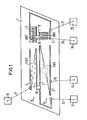
- each track consists of an input transducer EW1 or EW2 with an interdigital structure schematically indicated in the drawing and with busbars or Busbars 2, 3 and 4, 5.
- bus bars 3, 4 and bus bar 2 which are in contact with each other at 10, are connected via bond wires 13 and 15 to the terminals 12 and 14 on the input side.
- the output converters AW1 and AW2 are connected in parallel in the illustrated embodiment.
- the busbars 7, 8 are in contact with one another via a contact 11 and via a bonding wire 19 with the connection 18 and the busbars 6, 9 contacted with one another via a bonding wire 21 with the connection 20.
- track A is designed for a pass band which is larger than track B. If you transmit the signal of larger bandwidth in track A, e.g. the signal of a bandwidth of 5 MHz corresponding to the B / G standard and in track B the difference signal - bandwidth 1 MHz - to the 4 MHz bandwidth customary in the M standard, the corresponding 4 MHz wide signal is obtained at the filter output.
- the signal of larger bandwidth in track A e.g. the signal of a bandwidth of 5 MHz corresponding to the B / G standard and in track B the difference signal - bandwidth 1 MHz - to the 4 MHz bandwidth customary in the M standard.
- track A is always electrically active, i.e. the bus bars 3, 4 of the input converters EW1 and EW2 at a higher potential and the bus bars 2, 5 at a lower potential, i.e. usually grounded. Due to the parallel connection of the two output converters AW1 and AW2, the signals of both tracks add up in this way. If only the input converter EW1 is activated, i.e. in the event that busbar 5 is not at the potential of busbar 2, only the signal of larger bandwidth is transmitted.
Landscapes
- Physics & Mathematics (AREA)
- Acoustics & Sound (AREA)
- Surface Acoustic Wave Elements And Circuit Networks Thereof (AREA)
- Ac-Ac Conversion (AREA)
- Emergency Protection Circuit Devices (AREA)
Claims (6)
- Filtre à ondes acoustiques de surface comportant une bande passante modifiable, caractérisé par le fait qu'il est prévu au moins deux pistes parallèles (A,B) comportant des transducteurs d'entrée et de sortie (EW1,EW2 et AW1,AW2), que les barres omnibus (2,3) d'un transducteur (EW1) d'une piste (A) sont placées à des potentiels différents, qu'une barre omnibus (4) d'un transducteur (EW2) d'au moins une autre piste (B) est placée à l'un des deux potentiels tandis que l'autre barre omnibus (5) peut être raccordée au choix à l'un de ces potentiels de sorte que la bande passante du filtre peut être sélectionnée au moyen du raccordement et du débranchement des différentes pistes (A,B) possédant des bandes passantes différentes.
- Filtre à ondes de surface suivant la revendication 1, caractérisé par le fait qu'il est prévu deux pistes parallèles (A,B), que les barres omnibus (2,3) du transducteur d'entrée (EW1) de la première piste (A) sont placées à des potentiels différents, et qu'une barre omnibus (4) du transducteur d'entrée (EW2) de la seconde piste (B) est placée à l'un de ces deux potentiels tandis que l'autre barre omnibus (5) est placée au choix à l'un de ces potentiels.
- Filtre à ondes de surface suivant la revendication 1, caractérisé par le fait qu'il est prévu deux pistes parallèles (A,B), que les barres omnibus (6,7) du transducteur de sortie (AW1) de la première piste (A) sont placés à des potentiels différents et qu'une barre omnibus (8) du transducteur de sortie (AW2) de la seconde piste (B) est placée à l'un de ces deux potentiels tandis que l'autre barre omnibus (9) est placée au choix à l'un de ces potentiels.
- Filtre à ondes de surface suivant la revendication 2 ou 3, caractérisé par le fait que les transducteurs de sortie (AW1,AW2) des deux pistes (A,B) sont branchés en parallèle.
- Filtre à ondes de surface suivant la revendication 2 ou 3, caractérisé par le fait que les transducteurs de sortie des deux pistes (A,B) sont branchés en série.
- Filtre à ondes de surface suivant la revendication 1 et l'une des revendications précédentes, caractérisé par son utilisation en tant que filtre de fréquences moyennes pour des récepteurs de télévision à normes multiples de manière qu'en fonction de la norme désirée, le filtre de fréquences intermédiaires puisse être commuté dans la bande passante correspondante.
Priority Applications (6)
| Application Number | Priority Date | Filing Date | Title |
|---|---|---|---|
| ES198888118879T ES2040816T3 (es) | 1988-11-11 | 1988-11-11 | Filtro de ondas superficiales con zona de paso variable. |
| EP88118879A EP0367864B1 (fr) | 1988-11-11 | 1988-11-11 | Dispositif à ondes acoustiques de surface à bande passante variable |
| DE8888118879T DE3878562D1 (de) | 1988-11-11 | 1988-11-11 | Oberflaechenwellenfilter mit aenderbarem durchlassbereich. |
| AT88118879T ATE85870T1 (de) | 1988-11-11 | 1988-11-11 | Oberflaechenwellenfilter mit aenderbarem durchlassbereich. |
| JP1288587A JPH02181508A (ja) | 1988-11-11 | 1989-11-06 | 可変通過帯域表面波フイルタ |
| US07/435,810 US5107234A (en) | 1988-11-11 | 1989-11-13 | Surface-wave filter with selectively connectable tracks to provide a variable transmission band |
Applications Claiming Priority (1)
| Application Number | Priority Date | Filing Date | Title |
|---|---|---|---|
| EP88118879A EP0367864B1 (fr) | 1988-11-11 | 1988-11-11 | Dispositif à ondes acoustiques de surface à bande passante variable |
Publications (2)
| Publication Number | Publication Date |
|---|---|
| EP0367864A1 EP0367864A1 (fr) | 1990-05-16 |
| EP0367864B1 true EP0367864B1 (fr) | 1993-02-17 |
Family
ID=8199554
Family Applications (1)
| Application Number | Title | Priority Date | Filing Date |
|---|---|---|---|
| EP88118879A Expired - Lifetime EP0367864B1 (fr) | 1988-11-11 | 1988-11-11 | Dispositif à ondes acoustiques de surface à bande passante variable |
Country Status (6)
| Country | Link |
|---|---|
| US (1) | US5107234A (fr) |
| EP (1) | EP0367864B1 (fr) |
| JP (1) | JPH02181508A (fr) |
| AT (1) | ATE85870T1 (fr) |
| DE (1) | DE3878562D1 (fr) |
| ES (1) | ES2040816T3 (fr) |
Cited By (1)
| Publication number | Priority date | Publication date | Assignee | Title |
|---|---|---|---|---|
| DE19512251A1 (de) * | 1995-03-31 | 1996-10-10 | Siemens Ag | Oberflächenwellen-Doppelwandler für ein Doppelfilter, insbesondere für Fernsehempfangsgeräte |
Families Citing this family (7)
| Publication number | Priority date | Publication date | Assignee | Title |
|---|---|---|---|---|
| JP2636482B2 (ja) * | 1990-09-13 | 1997-07-30 | 日本電気株式会社 | 弾性表面波フィルタ |
| EP0489195A1 (fr) * | 1990-12-05 | 1992-06-10 | SIEMENS MATSUSHITA COMPONENTS GmbH & CO. KG | Filtre à fréquence intermédiaire pour l'utilisation quasi parallèle/parallèle de son |
| JP2944287B2 (ja) * | 1991-12-27 | 1999-08-30 | 日本電気株式会社 | 弾性表面波フィルタ |
| US5973578A (en) * | 1998-03-31 | 1999-10-26 | Unisor Multisystems Ltd | Programmable signal translating devices and method of programming such devices |
| DE10159449B4 (de) * | 2001-12-04 | 2012-05-03 | Epcos Ag | Schaltbares Oberflächenwellenfilter |
| DE102004037820A1 (de) * | 2004-08-04 | 2006-03-16 | Epcos Ag | Elektrische Schaltung und Bauelement mit der Schaltung |
| CN101316099B (zh) * | 2008-07-04 | 2010-06-16 | 无锡市好达电子有限公司 | 双通道声表面波滤波器 |
Family Cites Families (9)
| Publication number | Priority date | Publication date | Assignee | Title |
|---|---|---|---|---|
| DE2132985C3 (de) * | 1971-07-02 | 1981-06-04 | Siemens AG, 1000 Berlin und 8000 München | Piezoelektrisches Filter nach dem Oberflächenwellenprinzip |
| US3745564A (en) * | 1972-01-07 | 1973-07-10 | Rca Corp | Switchable acoustic surface wave device |
| GB1512790A (en) * | 1975-08-22 | 1978-06-01 | Mullard Ltd | Acoustic surface wave devices |
| GB1554366A (en) * | 1977-02-04 | 1979-10-17 | Philips Electronic Associated | Acoustic surface wave devices |
| DE3120050A1 (de) * | 1981-05-20 | 1982-12-09 | Licentia Patent-Verwaltungs-Gmbh, 6000 Frankfurt | Zf-verstaerker fuer einen mehrnormen-fernsehempfaenger |
| JPS5827417A (ja) * | 1981-08-12 | 1983-02-18 | Hitachi Ltd | 弾性表面波装置 |
| JPS5840911A (ja) * | 1981-09-04 | 1983-03-10 | Toshiba Corp | 弾性表面波フイルタ装置 |
| JPS63132515A (ja) * | 1986-11-25 | 1988-06-04 | Hitachi Ltd | 弾性表面波複合フイルタ |
| US4764701A (en) * | 1986-12-30 | 1988-08-16 | Zenith Electronics Corporation | Multichannel surface acoustic wave encoder/decoder |
-
1988
- 1988-11-11 ES ES198888118879T patent/ES2040816T3/es not_active Expired - Lifetime
- 1988-11-11 DE DE8888118879T patent/DE3878562D1/de not_active Expired - Lifetime
- 1988-11-11 AT AT88118879T patent/ATE85870T1/de not_active IP Right Cessation
- 1988-11-11 EP EP88118879A patent/EP0367864B1/fr not_active Expired - Lifetime
-
1989
- 1989-11-06 JP JP1288587A patent/JPH02181508A/ja active Pending
- 1989-11-13 US US07/435,810 patent/US5107234A/en not_active Expired - Fee Related
Cited By (1)
| Publication number | Priority date | Publication date | Assignee | Title |
|---|---|---|---|---|
| DE19512251A1 (de) * | 1995-03-31 | 1996-10-10 | Siemens Ag | Oberflächenwellen-Doppelwandler für ein Doppelfilter, insbesondere für Fernsehempfangsgeräte |
Also Published As
| Publication number | Publication date |
|---|---|
| JPH02181508A (ja) | 1990-07-16 |
| ES2040816T3 (es) | 1993-11-01 |
| EP0367864A1 (fr) | 1990-05-16 |
| ATE85870T1 (de) | 1993-03-15 |
| US5107234A (en) | 1992-04-21 |
| DE3878562D1 (de) | 1993-03-25 |
Similar Documents
| Publication | Publication Date | Title |
|---|---|---|
| DE69633820T2 (de) | Oberflächenwellenfilter mit verbesserten Bandpasseigenschaften und verbessertem Einstellbereich der Eingangs- und Ausgangsimpedanzen | |
| DE102005032058B4 (de) | HF-Filter mit verbesserter Gegenbandunterdrückung | |
| DE19724259C2 (de) | Dualmode-Oberflächenwellenfilter | |
| DE2846510C2 (fr) | ||
| DE69734753T2 (de) | Akustische Oberflächenwellenvorrichtung | |
| DE19818826B4 (de) | Oberflächenwellenfilter mit erhöhter Bandbreite | |
| EP1064724B1 (fr) | Filtre acoustique a ondes de surface | |
| DE3048817A1 (de) | Akustische oberflaechenwellenvorrichtung | |
| EP1256172B1 (fr) | Filtre a ondes acoustiques de surface dote d'elements de reactance | |
| EP0367864A1 (fr) | Dispositif à ondes acoustiques de surface à bande passante variable | |
| DE10325798B4 (de) | SAW-Filter mit verbesserter Selektion oder Isolation | |
| EP0709957B1 (fr) | Composant à ondes acoustiques de surface et son procédé de fabrication | |
| DE2531151B2 (de) | Mit elastischen Oberflächenwellen arbeitende elektromechanische Einrichtung | |
| DE102016123701A1 (de) | SAW-Filter mit hoher Bandbreite | |
| EP0105998B1 (fr) | Circuit intégré d'un filtre numérique pour le canal de luminance d'appareils de télévision en couleurs | |
| DE102010055648B4 (de) | Filterbauelement | |
| DE102011101756B4 (de) | Oberflächenwellenfilterbauelement | |
| DE2314642A1 (de) | Filter fuer akustische wellen | |
| DE19513793C2 (de) | Akustisches Oberflächenwellenfilter | |
| EP0808060B1 (fr) | Circuit amplificateur avec filtre pour signaux numériques et analogiques | |
| DE69724689T2 (de) | Akustischer Oberflächenwellenfilter | |
| DE2426375C3 (de) | Akustische Oberflächenwellenanordnung | |
| EP0735672B1 (fr) | Transducteur double à ondes acoustiques de surface pour filtre double, notamment pour récepteurs de télévision | |
| DE4227362C2 (de) | Akustisches Oberflächenwellenbauelement | |
| DE2235233B2 (de) | Filter oder verzoegerungsleitung nach dem oberflaechenwellenprinzip |
Legal Events
| Date | Code | Title | Description |
|---|---|---|---|
| PUAI | Public reference made under article 153(3) epc to a published international application that has entered the european phase |
Free format text: ORIGINAL CODE: 0009012 |
|
| AK | Designated contracting states |
Kind code of ref document: A1 Designated state(s): AT BE CH DE ES FR GB IT LI NL SE |
|
| 17P | Request for examination filed |
Effective date: 19900625 |
|
| 17Q | First examination report despatched |
Effective date: 19920416 |
|
| GRAA | (expected) grant |
Free format text: ORIGINAL CODE: 0009210 |
|
| AK | Designated contracting states |
Kind code of ref document: B1 Designated state(s): AT BE CH DE ES FR GB IT LI NL SE |
|
| REF | Corresponds to: |
Ref document number: 85870 Country of ref document: AT Date of ref document: 19930315 Kind code of ref document: T |
|
| REF | Corresponds to: |
Ref document number: 3878562 Country of ref document: DE Date of ref document: 19930325 |
|
| ET | Fr: translation filed | ||
| ITF | It: translation for a ep patent filed | ||
| GBT | Gb: translation of ep patent filed (gb section 77(6)(a)/1977) |
Effective date: 19930423 |
|
| REG | Reference to a national code |
Ref country code: ES Ref legal event code: FG2A Ref document number: 2040816 Country of ref document: ES Kind code of ref document: T3 |
|
| PLBE | No opposition filed within time limit |
Free format text: ORIGINAL CODE: 0009261 |
|
| STAA | Information on the status of an ep patent application or granted ep patent |
Free format text: STATUS: NO OPPOSITION FILED WITHIN TIME LIMIT |
|
| 26N | No opposition filed | ||
| PGFP | Annual fee paid to national office [announced via postgrant information from national office to epo] |
Ref country code: AT Payment date: 19941027 Year of fee payment: 7 |
|
| PGFP | Annual fee paid to national office [announced via postgrant information from national office to epo] |
Ref country code: ES Payment date: 19941107 Year of fee payment: 7 |
|
| PGFP | Annual fee paid to national office [announced via postgrant information from national office to epo] |
Ref country code: BE Payment date: 19941114 Year of fee payment: 7 |
|
| PGFP | Annual fee paid to national office [announced via postgrant information from national office to epo] |
Ref country code: SE Payment date: 19941116 Year of fee payment: 7 |
|
| EAL | Se: european patent in force in sweden |
Ref document number: 88118879.1 |
|
| PG25 | Lapsed in a contracting state [announced via postgrant information from national office to epo] |
Ref country code: AT Effective date: 19951111 |
|
| PG25 | Lapsed in a contracting state [announced via postgrant information from national office to epo] |
Ref country code: SE Effective date: 19951112 |
|
| PG25 | Lapsed in a contracting state [announced via postgrant information from national office to epo] |
Ref country code: ES Free format text: LAPSE BECAUSE OF EXPIRATION OF PROTECTION Effective date: 19951113 |
|
| PG25 | Lapsed in a contracting state [announced via postgrant information from national office to epo] |
Ref country code: BE Effective date: 19951130 |
|
| BERE | Be: lapsed |
Owner name: SIEMENS A.G. Effective date: 19951130 |
|
| EUG | Se: european patent has lapsed |
Ref document number: 88118879.1 |
|
| REG | Reference to a national code |
Ref country code: CH Ref legal event code: NV Representative=s name: E. BLUM & CO. PATENTANWAELTE |
|
| REG | Reference to a national code |
Ref country code: ES Ref legal event code: FD2A Effective date: 20010301 |
|
| REG | Reference to a national code |
Ref country code: CH Ref legal event code: PUE Owner name: SIEMENS AKTIENGESELLSCHAFT TRANSFER- EPCOS AG * SI |
|
| REG | Reference to a national code |
Ref country code: FR Ref legal event code: TP |
|
| REG | Reference to a national code |
Ref country code: GB Ref legal event code: IF02 |
|
| NLS | Nl: assignments of ep-patents |
Owner name: EPCOS AG |
|
| PGFP | Annual fee paid to national office [announced via postgrant information from national office to epo] |
Ref country code: NL Payment date: 20021021 Year of fee payment: 15 Ref country code: CH Payment date: 20021021 Year of fee payment: 15 |
|
| PG25 | Lapsed in a contracting state [announced via postgrant information from national office to epo] |
Ref country code: LI Free format text: LAPSE BECAUSE OF NON-PAYMENT OF DUE FEES Effective date: 20031130 Ref country code: CH Free format text: LAPSE BECAUSE OF NON-PAYMENT OF DUE FEES Effective date: 20031130 |
|
| PG25 | Lapsed in a contracting state [announced via postgrant information from national office to epo] |
Ref country code: NL Free format text: LAPSE BECAUSE OF NON-PAYMENT OF DUE FEES Effective date: 20040601 |
|
| REG | Reference to a national code |
Ref country code: CH Ref legal event code: PL |
|
| NLV4 | Nl: lapsed or anulled due to non-payment of the annual fee |
Effective date: 20040601 |
|
| PG25 | Lapsed in a contracting state [announced via postgrant information from national office to epo] |
Ref country code: IT Free format text: LAPSE BECAUSE OF NON-PAYMENT OF DUE FEES;WARNING: LAPSES OF ITALIAN PATENTS WITH EFFECTIVE DATE BEFORE 2007 MAY HAVE OCCURRED AT ANY TIME BEFORE 2007. THE CORRECT EFFECTIVE DATE MAY BE DIFFERENT FROM THE ONE RECORDED. Effective date: 20051111 |
|
| PGFP | Annual fee paid to national office [announced via postgrant information from national office to epo] |
Ref country code: GB Payment date: 20071128 Year of fee payment: 20 Ref country code: FR Payment date: 20071119 Year of fee payment: 20 |
|
| PGFP | Annual fee paid to national office [announced via postgrant information from national office to epo] |
Ref country code: DE Payment date: 20071221 Year of fee payment: 20 |
|
| REG | Reference to a national code |
Ref country code: GB Ref legal event code: PE20 Expiry date: 20081110 |
|
| PG25 | Lapsed in a contracting state [announced via postgrant information from national office to epo] |
Ref country code: GB Free format text: LAPSE BECAUSE OF EXPIRATION OF PROTECTION Effective date: 20081110 |