EP0368526B1 - Embrayage - Google Patents
Embrayage Download PDFInfo
- Publication number
- EP0368526B1 EP0368526B1 EP89311170A EP89311170A EP0368526B1 EP 0368526 B1 EP0368526 B1 EP 0368526B1 EP 89311170 A EP89311170 A EP 89311170A EP 89311170 A EP89311170 A EP 89311170A EP 0368526 B1 EP0368526 B1 EP 0368526B1
- Authority
- EP
- European Patent Office
- Prior art keywords
- rotatable member
- coil spring
- rotatable
- way clutch
- rotation
- Prior art date
- Legal status (The legal status is an assumption and is not a legal conclusion. Google has not performed a legal analysis and makes no representation as to the accuracy of the status listed.)
- Expired - Lifetime
Links
- 238000004804 winding Methods 0.000 claims description 23
- 230000033001 locomotion Effects 0.000 claims description 7
- 230000005540 biological transmission Effects 0.000 description 8
- 238000010276 construction Methods 0.000 description 6
- 230000006835 compression Effects 0.000 description 2
- 238000007906 compression Methods 0.000 description 2
- 230000007257 malfunction Effects 0.000 description 2
- 230000002093 peripheral effect Effects 0.000 description 2
- 238000010438 heat treatment Methods 0.000 description 1
- 239000000126 substance Substances 0.000 description 1
- 239000002699 waste material Substances 0.000 description 1
Images






Classifications
-
- F—MECHANICAL ENGINEERING; LIGHTING; HEATING; WEAPONS; BLASTING
- F16—ENGINEERING ELEMENTS AND UNITS; GENERAL MEASURES FOR PRODUCING AND MAINTAINING EFFECTIVE FUNCTIONING OF MACHINES OR INSTALLATIONS; THERMAL INSULATION IN GENERAL
- F16D—COUPLINGS FOR TRANSMITTING ROTATION; CLUTCHES; BRAKES
- F16D41/00—Freewheels or freewheel clutches
- F16D41/20—Freewheels or freewheel clutches with expandable or contractable clamping ring or band
- F16D41/206—Freewheels or freewheel clutches with expandable or contractable clamping ring or band having axially adjacent coils, e.g. helical wrap-springs
-
- F—MECHANICAL ENGINEERING; LIGHTING; HEATING; WEAPONS; BLASTING
- F16—ENGINEERING ELEMENTS AND UNITS; GENERAL MEASURES FOR PRODUCING AND MAINTAINING EFFECTIVE FUNCTIONING OF MACHINES OR INSTALLATIONS; THERMAL INSULATION IN GENERAL
- F16D—COUPLINGS FOR TRANSMITTING ROTATION; CLUTCHES; BRAKES
- F16D43/00—Automatic clutches
- F16D43/02—Automatic clutches actuated entirely mechanically
Definitions
- the present invention relates generally to a clutch for transmitting torque between an input and an output, and more particularly to a clutch for transmitting torque in one direction but not in the other.
- a one-way clutch is well known in the art and is utilized for electric power steering in motor vehicles, for example.
- This clutch is disposed between an electric motor and a steering shaft to connect therebetween for transmitting torque in one particular state, but not in another.
- a clutch cam is inserted into a large cylindrical portion of the clutch via rollers. By pressing the rollers against the large cylindrical portion by the clutch cam, relative rotation between the large cylindrical portion and the clutch cam is stopped to allow torque to be transmitted.
- a one-way clutch is well known in the art which includes two rotatable members, as input and output shafts, mounted for rotation relative to each other and a coil spring wound across the rotatable members.
- the coil spring When the coil spring is put around the rotatable members tightly, the rotatable members rotate simultaneously with each other to transmit torque therebetween.
- skidding occurs between the rotatable members and torque is not transmitted.
- GB-A-436 2844 an which the preamble of claim 1 is based, discloses a free-wheel driving mechanism in which interlaced helical drive springs encircle the end portions of co-axial input and output shafts. At the output end, the ends of the springs are turned outwards and engaged by a sleeve. The sleeve is encircled by a further helical spring, one end of which is secured to a fixed member. If the driving shaft is turned in the driving direction, the helical driving springs tighten and transmit torque from the driving to the driven shaft, while the further helical spring relaxes and allows the sleeve to revolve with the shafts.
- the helical driving springs expand and relax, and no torque is transmitted. If, however, the output shaft is turned backwards, the helical driving springs and the sleeve begin to rotate, and the further helical spring then tightens and locks the sleeve. The helical driving springs then expand, freeing the output shaft and allowing it to rotate backwards without rotating the input shaft.
- a disadvantage of that type of clutch is that when torque is being transmitted the further helical spring drags on the sleeve, causing waste of power, heating, and wear.
- the invention provides a clutch comprising: a first rotatable member; a second rotatable member provided for rotational movement relative to said first rotatable member; engaging means for engaging between said first and second rotatable members, said engaging means including a coil spring wound over said first and second rotatable members, the coil spring being deformed according to rotation of said second rotatable member in one direction so as to be reduced in diameter so as to fasten together said first and second rotatable members to form a connection therebetween; and means for controlling said engaging means so as to allow said first rotatable member to rotate independently of said second rotatable member according to rotation of said first rotatable member, said means including a third rotatable member connected to a part of said coil spring and means allowing said third rotatable member to rotate in a release direction of said coil spring in response to rotation of said first rotatable member in one direction and preventing the third rotatable member from rotating in a winding direction of said coil spring in response to rotation of said first
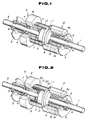
- This clutch includes a rotatable shaft 1 as a first rotatable member and a rotatable hollow cylinder 6 as a second rotatable member.
- the first rotatable member 1 includes a small diameter section 3 and a large diameter section 2, which extends radially from the middle portion of section 3.
- the small diameter section 3 is rotatably supported by a bracket 5 and bearings 4.
- the second rotatable member 6 is rotatably mounted on one side of the small diameter section 3 via bearings 7.
- the second rotatable member 6 includes a cylinder 9 and a disc 8 radially extending outwardly at the end of the cylinder.
- the cylinder 9 has a diameter equal to that of the large diameter section 2 of the first rotatable member 1 and abuts thereto at its end.
- a coil spring 10 is wound around the large diameter section 2 and the cylinder 9.
- the coil spring 10 is wound from right to left and the folded end (the left end) 11 thereof is fixedly attached to the rotation control cylinder 12.
- the rotation control cylinder 12 comprises a one-way clutch 13 disposed on a cylindrical portion 5a of the bracket 5 and a cylindrical holder 14 mounted so as to surround the one-way clutch.
- the one-way clutch is such that power can be transmitted in one direction but not in the other.
- the rotation control cylinder 12 therefore prevents the end 11 of the coil spring 10 from rotating in the winding direction but allows it to rotate in the release direction.
- transmission of torque to the first rotatable member 1 to rotate it in the clockwise direction causes the coil spring 10 to be twisted in the rotational direction of the first rotatable member 1 (i.e., in the release direction) by friction created between contacting surfaces of the large diameter section 2 and the coil spring 10.
- the coil spring is deformed so as to be spread radially outward.
- the first rotatable member 1 and the second rotatable member 6 may rotate independently of each other. Therefore, no torque is transmitted to the second rotatable member 6 from the first rotatable member.
- the rotation control cylinder 12 is rotatable in the clockwise direction to allow the coil spring to rotate in the release direction.
- transmission of torque to the second rotatable member 6 to rotate it in the clockwise direction causes the coil spring 10 to be twisted in the rotational direction of the second rotatable member 6 (i.e., in the winding direction) by friction created between contacting surfaces of the cylinder 9 and the coil spring 10.
- the coil spring is deformed so as to be drawn radially inward.
- the first rotatable member 1 and the second rotatable member 6 are clamped by the coil spring allowing frictional force to be created therebetween, causing the two rotatable members 1 and 6 to rotate integrally to transmit torque from the second rotatable member 6 to the first rotatable member 1.
- the rotation control cylinder 12 since the rotation control cylinder 12 is rotatable in the clockwise direction without limitation, it rotates synchronously with the first and the second rotatable members 1 and 6.
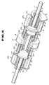
- FIG. 2 there is illustrated a modified form of the first embodiment. Construction of this clutch is the same as the clutch shown in Fig. 1 except a one-way clutch 20, which is installed on the cylinder 9, is provided.
- This one-way clutch 20 comprises rollers 21 and a casing 22 for accommodating the rollers.
- the casing has an outer diameter equal to that of a large diameter section 2.
- the one-way clutch, 20 is adapted for allowing the second rotatable member 6 to rotate in the counterclockwise direction.
- a coil spring 10 is provided around the casing 22 and the large diameter section 2 of the first rotatable member 1 similarly to the previous embodiment.
- transmission of torque to the first rotatable member 1 to rotate it in the clockwise direction causes the coil spring 10 to be twisted in the rotational direction of the first rotatable member 1 (i.e., in the release direction) by friction created between contacting surfaces of the large diameter section 2 and the coil spring 10.
- the coil spring is deformed so as to be spread radially outward.
- the one-way clutch 20 rolls so as to allow rotational movement in the clockwise direction of the coil spring.
- the first rotatable member 1 and the second rotatable member 6 rotate independently of each other. No torque is therefore transmitted to the second rotatable member 6 from the first rotatable member.
- the rotation control cylinder 12 is rotatable in the clockwise direction to allow the coil spring to rotate in the release direction.
- a second embodiment of a clutch according to the invention is shown.
- a holder 14 for a rotation control cylinder 12 extends closely to a disc portion 8 of a second rotatable member 6 and an end 11 of a coil spring 10 engages an extended end of the holder.
- the rotation control member 12 may rotate in a direction opposite that of the first embodiment (i.e., the counterclockwise direction), allowed by the rotational direction of a one-way clutch 13. While these two points are different from the above mentioned first embodiment, the other elements of construction are essentially the same.
- rotation of the first rotatable member 1 in the clockwise direction causes the coil spring to be spread so as to allow the first rotatable member to rotate independently from second rotatable member 6. Therefore, no torque is transmitted to the second rotatable member from the first rotatable member.
- Rotation of a first rotatable member 1 in the clockwise direction causes the coil spring to be deformed so as to be drawn in radially and thus the first rotatable member 1 and a second rotatable member 6 are locked together via the coil spring 10 due to the tight compression of the coil spring 10.
- the rotation control cylinder 12 can rotate in the counterclockwise direction.
- the first rotatable member 1 rotates in the counterclockwise direction in cooperation with the second rotatable member 6 to transmit torque to the second rotatable member 6.
- Rotation of the second rotatable member 6 in the clockwise direction causes the end 11 of the coil spring 10, connected to the rotational control cylinder, to be prevented from rotating by the rotation control cylinder.
- no binding force is provided by the coil spring 10 between the first and second rotatable members 1 and 6 and therefore no torque is provided to the first rotatable member from the second rotatable member.
- Rotation of the second rotatable member 6 in the counterclockwise direction causes the coil spring 10 to be spread in the release direction so as to reduce frictional force between the coil spring and the large diameter section 2 of the first rotatable member 1, allowing the second rotatable member 6 to rotate independently of the first rotatable member 1. Thus, no torque is transmitted to the first rotatable member 1.
- FIG. 4 there is illustrated a modified form of the second embodiment. Construction of this clutch is the same as the clutch shown in Fig. 3 except for the provision of a one-way clutch 20 which is installed on the cylinder 9.
- the one-way clutch 20 is adapted for allowing the second rotatable member 6 to rotate only in the counterclockwise direction.
- Rotation of the first rotatable member 1 in the clockwise direction causes the coil spring to be deformed so as to be drawn inwardly and thus the first rotatable member 1 and the one-way clutch 20 are fastened by the coil spring 10 and locking of the one-way clutch 10 is encountered causing the one-way clutch to rotate synchronously with the second rotatable member 6. Since the rotation control cylinder 12 can rotate in the counterclockwise direction, it rotates synchronously with the first and second rotatable members 1 and 6. Thus, torque is transmitted to the second rotatable member from the first rotatable member.
- Rotation of the second rotatable member 6 in the clockwise direction causes the one-way clutch 20 to lock.
- the one-way clutch 20 and the second rotatable member 6 rotate synchronously. Twisting of the end portion 11 of the coil spring 10 in the winding direction (i.e., in the clockwise direction) is restricted by the rotation control cylinder 12 because another one-way clutch 13 prevents the cylinder 12 from rotating in the clockwise direction.
- the one-way clutch 20 (and thus, the second rotatable member 6) and the first rotatable member 1 are not fastened by the coil spring 10.
- sliding occurs between the one-way clutch 20 and the coil spring 10 transmitting no torque to the first rotatable member 1 from the second rotatable member 6.
- Rotation of the second rotatable member 6 in the counterclockwise direction causes the one-way clutch 20 to rotate. No torque therefore, is transmitted to the first rotatable member 1 from the second rotatable member 6.
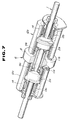
- a clutch of a third embodiment according to the invention is shown.
- This clutch includes a first rotatable member 1 which has a pair of large diameter sections 2a and 2b each extending radially outward and spaced from each other by a given distance.
- the first rotatable member 1 is rotatably supported by a bracket 5 via bearings 4.
- a second rotatable member 6 is arranged between the pair of large diameter sections 2a and 2b for rotation relative to the middle portion 3 of the first rotatable member 1 by a pair of bearings 7.
- the second rotatable member 6 includes a disc 8 radially extending from the middle thereof and cylinders 9a and 9b formed at both sides of the disc.
- the cylinders 9a and 9b have diameters equal to those of large diameter sections 2a and 2b so as to be aligned with the pair of large diameter sections 2a and 2b.
- a first coil spring 10a and a second coil spring 10b are wound around the large diameter section 2a and the cylinder 9a and the large diameter section 2b and the cylinder 9b respectively.
- Each of the coil springs 10a and 10b is wound in the clockwise direction in the drawing. Folded end 11a of the first coil spring 10a engages a rotation control cylinder 12a and folded end 11b of the second coil spring 10b engages a rotation control cylinder 12b.
- the rotation control cylinder 12a prevents the coil spring 10a from rotating in the winding direction (i.e., in the clockwise direction), while the rotation control cylinder 12b prevents the coil spring 10b from rotating in the winding direction (i.e., in the counterclockwise direction).
- Each of the rotation control cylinders 12a and 12b is, similar to the above embodiment, provided with a one-way clutch 13 mounted on a cylinder 5a of a bracket 5 and a holder 14 installed on the periphery of the one-way clutch 13.
- rotation of the first rotatable member 1 in the clockwise direction causes the second coil spring 10b to be spread, while the first coil spring 10a is prevented from contracting (ie., it may rotate in the winding direction) by the rotation control cylinder 12a. Therefore, binding between the large diameter section 2a of the first rotatable member 1 and the cylinder 9a of the second rotatable member 6, encased by the first coil spring 10a does not take place. The first coil spring is deformed so as to be spread. The first rotatable member 1 and the second rotatable member 6 do not rotate together therefore torque is not transmitted to the second rotatable member 6 from the first rotatable member 1.
- Rotation of the first rotatable member 1 in the counterclockwise direction causes the second coil spring 10b to be prevented from reducing in diameter (i.e., rotating in the winding direction). No fastening force caused by the second coil spring 10b is therefore provided for the large diameter section 2b of the first rotatable member 1 and the cylinder 9b of the second rotatable member 6 and the first coil spring 10a to be extended in diameter.
- the first rotatable member 1 rotates independently upon the second rotatable member 6 to provide no torque to the second rotatable member from the first rotatable member.
- Rotation of the second rotatable member 6 in the clockwise direction causes the second coil spring to draw inwardly, becoming small in diameter, thereby fastening together the cylinder 9b of the second rotatable member and the large diameter section 2b of the first rotatable member 1.
- the first spring 10a conversely, expands so as to be spread.
- the first rotatable member 1, the second rotatable member 6, and the rotation control cylinder 12b synchronously rotate in the clockwise direction to transmit torque to the first rotatable member from the second rotatable member.
- Rotation of the second rotatable member 6 in the counterclockwise direction causes the second coil spring 10 to be spread and the first coil spring 10a to be drawn inwardly so as to fasten together the cylinder 9a of the second rotatable member 6 and the large diameter section 2a of the first rotatable member 1.
- the first rotatable member 1, the second rotatable member 6, and the rotation control cylinder 12a therefore rotate synchronously in the counterclockwise direction to transmit torque to the first rotatable member from the second rotatable member 6.
- a modified form of the third embodiment is shown.
- the construction of the clutch is essentially the same as the clutch shown in Fig. 5 except for the provision of one-way clutches 20a and 20b installed on cylinders 9a and 9b.
- Each one-way clutch comprises rollers 21 and a casing 22 for accommodating the rollers which have an outer diameter substantially equal to that of the large diameter section of the first rotatable member 1.
- the one-way clutch 20a is adapted for allowing the second rotatable member to rotate in the clockwise direction, while the one-way clutch 20b is adapted for allowing the second rotatable member 6 to rotate in the counterclockwise direction.
- Coil springs 10a and 10b are wound around the casings 22 and the large diameter sections 2a and 2b.
- rotation of the first rotatable member 1 in the clockwise direction causes the second coil spring 10b to be spread, while the first coil spring 10a is prevented from contracting (i.e., it rotates in the winding direction) by the rotation control cylinder 12a.
- No binding force created by the first coil spring 10a is therefore provided to the large diameter section 2a of the first rotatable member 1 and the one-way clutch 20a.
- the first rotatable member 1 can rotate independently of the second rotatable member 6 providing no torque to the second rotatable member from the first rotatable member.
- Rotation of the first rotatable member 1 in the counterclockwise direction causes the second coil spring 10b to be prevented from drawing inwardly (i.e., rotating in the winding direction). No binding force is therefore caused by the second coil spring 10b provided for the large diameter section 2b of the first rotatable member 1 and the one-way clutch 20b.
- the first coil spring 10a is spread, thus extending in diameter, and the first rotatable member 1 rotates independently of the second rotatable member 6 providing no torque to the second rotatable member from the first rotatable member.
- Rotation of the second rotatable member 6 in the clockwise direction causes the one-way clutch 20b to be locked so as to rotate with the second rotatable member 6 and the other one-way clutch 20a rolls around the cylinder 9a of the second rotatable member 6.
- the second coil spring 10b therefore contracts in diameter so that the second coil spring fastens together the large diameter section 2b of the first rotatable member and the one-way clutch 20b, the second rotatable member rotating thereby with the first rotatable member to transmit torque to the first rotatable member.
- the rotation control cylinder 12b rotates with the first and the second rotatable members 1 and 6.
- Rotation of the second rotatable member 6 in the counterclockwise direction causes the one-way clutch 20b to roll around the cylinder 9b of the second rotatable member 6 and the one-way clutch 20a to be locked so as to rotate with the second rotatable member 6.
- Clamping force caused by the first coil spring 10a is provided for the large diameter section 2a and the one-way clutch 20a.
- the second rotatable member rotates with the first rotatable member 1 to transmit torque to the first rotatable member.
- the rotation control cylinder 12a rotates synchronously with the first and the second rotatable members 1 and 6.
- a fourth embodiment of a clutch according to the invention differs from the clutch of the third embodiment in that holders 14 of rotation control cylinders 12a and 12b extend closely to a disc portion 8 of the second rotatable member 6 and end portions 11a and 11b of coil springs 10a and 10b engage the extended sections thereof. Additionally, in this embodiment, a one-way clutch 13b on the right side allows the rotation control cylinder 12b to rotate only in the counterclockwise direction, while a one-way clutch 13a on the left side allows the rotation control cylinder 12a to rotate only in the clockwise direction. Otherwise, the construction is similar to that of the above mentioned third embodiment.
- rotation of the first rotatable member 1 in the clockwise direction causes the second coil spring 10b to spread and the first coil spring 10a to contract so as to fasten together the large diameter section 2a of the first rotatable member 1 and the cylinder 9a of the second rotatable member 6.
- the first and the second rotatable members 1 and 6 and the rotation control cylinder 12a rotate synchronously with each other in the clockwise direction to transmit torque to the second rotatable member from the first rotatable member.
- Rotation of the first rotatable member in the counterclockwise direction causes the second coil spring 10b to be reduced in diameter so as to fasten the large diameter section 2b of the first rotatable member 1 and the cylinder 9b of the second rotatable member 6 and the first coil spring 10a to be spread in diameter.
- the first and the second rotatable members 1 and 6 and the rotation control cylinder 12b therefore rotate synchronously in the counterclockwise direction to transmit torque to the second rotatable member from the first rotatable member.
- Rotation of the second rotatable member 6 in the clockwise direction causes the second coil spring 10b to be prevented from contracting (ie., rotating in the winding direction) by the rotation control cylinder 12b and the first coil spring 10a to be spread in diameter. No binding force caused by the second coil spring 10b is therefore provided to the large diameter section 2b of the first rotatable member 1 or the cylinder 9b of the second rotatable member 6.
- the second rotatable member 6 rotates independently of the first rotatable member 1 transmitting no torque to the first rotatable member.
- Rotation of the second rotatable member 6 in the counterclockwise direction causes the second coil spring 10b to be spread in diameter and the first coil spring 10a is prevented from contracting in diameter (i.e., rotating in the winding direction) by the rotation control cylinder 12a. No binding force caused by the first coil spring 10a is therefore provided to the large diameter section 2a of the first rotatable member 1 or the cylinder 9a of the second rotatable member 6.
- the second rotatable member 6 rotates independently of the first rotatable member 1 transmitting no torque to the first rototable member.
- This clutch includes one-way clutches 20a and 20b which are disposed between cylinders 9a and 9b of the second rotatable member 6 and first and second coil springs 10a and 10b respectively.
- the one-way clutch 20a allows the second rotatable member 6 to rotate only in the clockwise direction, while the other one-way clutch 20b allows the second rotatable member to rotate only in the counterclockwise direction.
- rotation of the first rotatable member 1 in the clockwise direction causes the second coil spring 10b to spread in diameter and the first coil spring 10a to be contract in diameter so as to fasten together the large diameter section 2a of the first rotatable member 1 and the one-way clutch 20a.
- the one-way clutch 20a is locked to rotate synchronously with the second rotatable member 6, while the one-way clutch 20b rolls around the cylinder 9b of the second rotatable member 6.
- the first and the second rotatable members 1 and 6 rotate synchronously with each other to transmit torque to the second rotatable member from the first rotatable member.
- the rotation control cylinder 12a also rotates with the first and the second rotatable members 1 and 6.
- Rotation of the first rotatable member in the counterclockwise direction causes the second coil spring 10b to be reduced in diameter so as to fasten together the large diameter section 2b of the first rotatable member 1 and one-way clutch 20b, the first coil spring 10a is spread in diameter.
- the one-way clutch 20b is, in turn, locked to rotate with the second rotatable member 6.
- the first and the second rotatable members 1 and 6 therefore rotate synchronously to transmit torque to the second rotatable member from the first rotatable member.
- the rotation control cylinder 12a also rotates with the first and the second rotatable members 1 and 6.
- Rotation of the second rotatable member 6 in the clockwise direction causes the one-way clutch 20a to roll around the cylinder 9a of the second rotatable member 6 and the other one-way clutch 20b to be locked to rotate with the second rotatable member 6.
- the second coil spring is urged in the winding direction (i.e., in the clockwise direction). That rotation of the end 11b in the winding direction is however limited by the rotation control cylinder 12b to cause skidding to occur between the one-way clutch 20b and the coil spring 10b.
- the second rotatable member 6 therefore rotates independently of the first rotatable member 1 transmitting no torque to the first rotatable member.
- Rotation of the second rotatable member 6 in the counterclockwise direction causes the one-way clutch 20a to lock, rotating with the second rotatable member 6 and the other one-way clutch 20b to roll around the cylinder 9b of the second rotatable member 6.
- the first coil spring is urged in the winding direction (i.e., in the counterclockwise direction). Rotational movement of the end 11a is however restricted by the rotaion control cylinder 12a to cause skidding to occur between the one-way clutch 20a and the coil spring 10a.
- the second rotatable member 6 therefore rotates independently of the first rotatable member 1 transmitting no torque to the first rotatable member.
- a clutch which includes a one-way clutch disposed between one rotatable member and a coil spring
- frictional resistance occurring between contacting surfaces of the coil spring and the rotatable members is reduced by the rotating one-way clutch.
- Torque of the rotating first or the second rotatable members can be reduced when no torque is transmitted therebetween. This results in reduced wear on the contact surfaces and improved durability of the clutch.
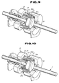
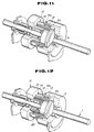
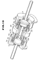
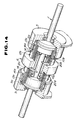
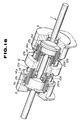
- FIGs. 9 to 17 modified forms of Figs. 1 to 8 are shown.
- the rotation control cylinders 12, 12a, and 12b shown in Figs. 1 to 8 are replaced by holders 14 which surround the outer peripheries of coil springs 10, 10a, and 10b for relative movement thereto and one-way clutches 13a and 13b which are mounted on the holders.
- Each of one-way clutches 13a and 13b is inserted into a housing formed in a cylindrical cavity 5a of a bracket 5.
- Each holder includes a flange 14a for positioning the axis of the one-way clutch.
- brackets As shown in Figs. 18 and 19, by extending brackets so as to cover coil springs, admission of foreign substances into contacting areas of the first and second rotatable members 1 and 6 can be avoided.
Landscapes
- Engineering & Computer Science (AREA)
- General Engineering & Computer Science (AREA)
- Mechanical Engineering (AREA)
- Mechanical Operated Clutches (AREA)
Claims (6)
- Embrayage comprenant : un premier élément rotatif (1) ; un second élément rotatif (6) prévu pour un mouvement de rotation par rapport au premier élément rotatif; un moyen d'engagement pour s'engager entre les premier et second éléments rotatifs, ledit moyen d'engagement comprenant un ressort hélicoïdal (10) enroulé sur les premier et second éléments rotatifs, le ressort hélicoïdal étant déformé selon la rotation du second élément rotatif dans une direction afin d'être réduit en diamètre pour fixer ensemble les premier et second éléments rotatifs pour former une liaison entre eux; et un moyen (12) pour commander ledit moyen d'engagement afin de permettre au premier élément rotatif de tourner indépendamment du second élément rotatif selon une rotation du premier élément rotatif, ledit moyen (12) comprenant un troisième élément rotatif (14) relié à une partie du ressort hélicoïdal et un moyen (13) permettant au troisième élément rotatif de tourner dans une direction de relâchement du ressort hélicoïdal en réponse à une rotation du premier élément rotatif dans une direction et empêchant le troisième élément rotatif de tourner dans un sens d'enroulement du ressort hélicoïdal en réponse à une rotation du premier élément rotatif dans l'autre direction pour permettre au premier élément rotatif de tourner indépendamment du second élément rotatif; caractérisé en ce que ledit moyen permettant au troisième élément rotatif de tourner et de l'empêcher de tourner comprend un embrayage unidirectionnel.
- Embrayage selon la revendication 1, comprenant un second embrayage unidirectionnel qui est disposé entre le ressort hélicoïdal précité et le second élément rotatif précité, ledit embrayage unidirectionnel tournant le ressort hélicoïdal suivant la rotation du second élément rotatif pour s'engager entre les premier et second éléments rotatifs de sorte que le premier élément rotatif tourne en synchronisme avec la rotation du second élément rotatif dans une direction, et le second embrayage unidirectionnel permettant au second élément rotatif de tourner indépendamment du ressort hélicoïdal lorsque le second élément rotatif tourne dans l'autre direction.
- Embrayage selon la revendication 1 ou la revendication 2, dans lequel le troisième élément rotatif comprend un élément cylindrique relié à la partie précitée du ressort hélicoïdal et l'embrayage unidirectionnel permet à l'élément cylindrique de tourner dans la direction de relâchement du ressort hélicoïdal et empêche l'élément cylindrique de tourner dans le sens d'enroulement.
- Embrayage selon l'une quelconque des revendications 1 à 3, dans lequel : le premier élément rotatif comprend un arbre et des premier et second disques s'étendant radialement situés sur l'arbre avec un espace donné entre eux; le second élément rotatif comprend un cylindre creux disposé entre les premier et second disques afin d'entourer l'arbre; le moyen d'engagement comprend un premier ressort hélicoïdal enroulé autour du premier disque et le cylindre creux pour s'engager entre eux selon la rotation du second élément rotatif dans une directionet un second ressort hélicoïdal enroulé autour du second disque et du cylindre creux pour s'engager entre eux selon la rotation du second élément rotatif dans l'autre direction; et le moyen de commande permet à l'un des premier et second ressorts hélicoïdaux d'être étendu et d'empêcher l'autre des premier et second ressorts hélicoïdaux d'être réduit en diamètre par la rotation du premier élément rotatif.
- Embrayage selon la revendication 4, dans lequel le moyen de commande comprend un premier ensemble rotatif comprenant un troisième élément rotatif relié à une partie du premier ressort hélicoïdal précité et un premier embrayage unidirectionnel et un second ensemble rotatif comprenant un quatrième élément rotatif relié à une partie du second ressort hélicoïdal et un second embrayage unidirectionnel, le premier ensemble rotatif permettant au premier ressort hélicoïdal de tourner dans la direction de relâchement de celui-ci et le second ensemble rotatif empêchant le second ressort hélicoïdal de tourner dans le sens d'enroulement de celui-ci selon la rotation du premier élément rotatif dans une direction, le premier ensemble rotatif empêchant le premier ressort hélicoïdal de tourner dans le sens d'enroulement et le second ensemble rotatif permettant au second ressort hélicoïdal de tourner dans la direction de relâchement de celui-ci selon la rotation du premier élément rotatif dans l'autre direction.
- Embrayage selon la revendication 5, dans lequel le moyen d'engagement comprend un troisième embrayage unidirectionnel disposé entre le premier ressort hélicoïdal et le second élément rotatif et un quatrième embrayage unidirectionnel disposé entre le second ressort hélicoïdal et le second ensemble rotatif, le troisième embrayage unidirectionnel permettant au second élément rotatif de tourner indépendamment du premier ressort hélicoïdal, tandis que le quatrième embrayage unidirectionnel fait tourner le second ressort hélicoïdal pour amener le premier élément rotatif à tourner en synchronisme avec le second élément rotatif selon la rotation du second élément rotatif dans ladite une direction, le quatrième embrayage unidirectionnel permettant au second élément rotatif de tourner indépendamment du second ressort hélicoïdal et le troisième embrayage unidirectionnel faisant tourner le premier ressort hélicoïdal pour amener le premier élément rotatif à tourner en synchronisme avec le second élément rotatif selon la rotation du second élément rotatif dans l'autre direction.
Applications Claiming Priority (6)
| Application Number | Priority Date | Filing Date | Title |
|---|---|---|---|
| JP27280388A JPH02120526A (ja) | 1988-10-28 | 1988-10-28 | クラッチ装置 |
| JP14746188U JPH0267124U (fr) | 1988-11-11 | 1988-11-11 | |
| JP147461/88 | 1988-11-11 | ||
| JP903/89 | 1989-01-06 | ||
| JP90389A JPH02186128A (ja) | 1989-01-06 | 1989-01-06 | クラッチ装置 |
| JP272803/88 | 1989-10-28 |
Publications (2)
| Publication Number | Publication Date |
|---|---|
| EP0368526A1 EP0368526A1 (fr) | 1990-05-16 |
| EP0368526B1 true EP0368526B1 (fr) | 1994-01-05 |
Family
ID=27274666
Family Applications (1)
| Application Number | Title | Priority Date | Filing Date |
|---|---|---|---|
| EP89311170A Expired - Lifetime EP0368526B1 (fr) | 1988-10-28 | 1989-10-30 | Embrayage |
Country Status (3)
| Country | Link |
|---|---|
| US (1) | US5022505A (fr) |
| EP (1) | EP0368526B1 (fr) |
| DE (1) | DE68912079T2 (fr) |
Families Citing this family (14)
| Publication number | Priority date | Publication date | Assignee | Title |
|---|---|---|---|---|
| US5856467A (en) * | 1990-12-21 | 1999-01-05 | Amylogene Hb | Genetically engineered modification of potato to form amylose-type starch |
| US5090530A (en) * | 1990-12-28 | 1992-02-25 | Dana Corporation | Wrap spring clutch/brake unit with spring differential adjustment |
| US5234089A (en) * | 1991-09-26 | 1993-08-10 | Ntn Corporation | Torque limiter |
| US5573472A (en) * | 1993-06-07 | 1996-11-12 | Ciolli; Donald A. | Wrap spring downshift mechanism |
| DE19814713A1 (de) * | 1998-04-02 | 1999-10-07 | Geiger Gerhard Gmbh & Co | Freilaufkupplung mit Schlingfeder |
| US6035745A (en) * | 1998-10-20 | 2000-03-14 | Kather; Scott D. | Indexing clutch assembly for gear wrench |
| JP2000346166A (ja) * | 1999-06-08 | 2000-12-12 | Ugk Kk | 動力伝達装置 |
| DE10064899A1 (de) * | 2000-12-23 | 2002-07-25 | Bosch Gmbh Robert | Vorrichtung zum Antreiben eines Ausgangsglieds |
| US6681909B2 (en) | 2001-04-03 | 2004-01-27 | Tecumseh Products Company | Walk-behind implement having wrap spring wheel clutches |
| US6817453B2 (en) * | 2001-06-25 | 2004-11-16 | Inventio Ag | Remote brake release with clutch |
| FR2898393B1 (fr) * | 2006-03-08 | 2009-02-20 | Bernard Sa L | Antidevireur a ressort. |
| EP2398547A1 (fr) * | 2009-02-20 | 2011-12-28 | Boston Scientific Scimed, Inc. | Sonde à ballonnet pouvant être soumise à un couple |
| US8678157B2 (en) * | 2011-05-25 | 2014-03-25 | Gates Corporation | Isolator decoupler |
| US9291253B1 (en) | 2015-03-24 | 2016-03-22 | Gates Corporation | Isolating decoupler |
Family Cites Families (13)
| Publication number | Priority date | Publication date | Assignee | Title |
|---|---|---|---|---|
| GB597776A (en) * | 1945-08-27 | 1948-02-03 | John Robert Collyear | Improvements in or relating to free-wheel driving mechanism |
| US1915885A (en) * | 1929-09-20 | 1933-06-27 | Gillett Edward Henry Jam Cecil | Freewheel device |
| FR689204A (fr) * | 1929-09-20 | 1930-09-03 | Perfectionnements aux dispositifs à roue libre | |
| GB436284A (en) * | 1934-02-09 | 1935-10-09 | John Robert Collyear | Improvements in or relating to free-wheel driving mechanisms |
| GB444176A (en) * | 1934-08-14 | 1936-03-16 | Thomas George Baxenden | Improvements in free wheel driving mechanism |
| GB444178A (en) * | 1934-08-15 | 1936-03-16 | Marconi Wireless Telegraph Co | Improvements in or relating to thermionic valve arrangements |
| GB780140A (en) * | 1955-08-10 | 1957-07-31 | Marquette Metal Products Co | Improvements in or relating to spring clutch mechanism |
| DE1174529B (de) * | 1962-09-26 | 1964-07-23 | Telefunken Patent | Antriebsanordnung fuer die Wickelteller von Magnetbandgeraeten |
| US3844390A (en) * | 1973-06-06 | 1974-10-29 | Marquette Metal Products Co | Single spring, bidirectional, anti-overtravel clutch |
| US3921771A (en) * | 1974-07-29 | 1975-11-25 | Marquette Metal Products Co | Clutch for providing intermittent rotary output from a source of continuous rotary power |
| US3990554A (en) * | 1975-07-02 | 1976-11-09 | Marquette Metal Products Company | Normally engaged spring clutch assembly drivable through either clutch drum |
| CH626960A5 (fr) * | 1978-05-12 | 1981-12-15 | Sulzer Ag | |
| JPH0819970B2 (ja) * | 1986-07-31 | 1996-03-04 | 三田工業株式会社 | 電磁制御ばねクラツチ機構 |
-
1989
- 1989-10-30 DE DE68912079T patent/DE68912079T2/de not_active Expired - Fee Related
- 1989-10-30 US US07/429,004 patent/US5022505A/en not_active Expired - Fee Related
- 1989-10-30 EP EP89311170A patent/EP0368526B1/fr not_active Expired - Lifetime
Also Published As
| Publication number | Publication date |
|---|---|
| DE68912079T2 (de) | 1994-06-01 |
| US5022505A (en) | 1991-06-11 |
| DE68912079D1 (de) | 1994-02-17 |
| EP0368526A1 (fr) | 1990-05-16 |
Similar Documents
| Publication | Publication Date | Title |
|---|---|---|
| US5022505A (en) | One-way clutch for transmitting only rotation of first member to second member | |
| US9651099B2 (en) | Clutched device with wrap spring clutch with overrun locking member | |
| JP2003104179A (ja) | 自動車両のためのパーキングロック装置 | |
| US4869357A (en) | Overrunning clutch with grooved bushing for reception of spring coil | |
| JPH0792107B2 (ja) | トルクリミッタ | |
| US5779015A (en) | One-way clutch having improved spring accomodating chamber | |
| KR20010007325A (ko) | 자동차용 이중 질량 댐핑 플라이휠 | |
| JP3631866B2 (ja) | クラッチ装置 | |
| EP0678685A1 (fr) | Embrayage à roue libre avec ressort à enroulement | |
| US6024197A (en) | Support structure for clutch hub | |
| US4538714A (en) | Wheel hub clutch assembly | |
| JP7478305B1 (ja) | トルクリミッタ | |
| JP4283167B2 (ja) | 紙送り機構 | |
| CA3158341C (fr) | Limiteur de couple bidirectionnel | |
| US5810139A (en) | Bicycle and a friction device for controlling a clamping roller coupling of a bicycle hub of a bicycle | |
| JPH05321943A (ja) | 過負荷防止装置 | |
| JP3551545B2 (ja) | スタータ用一方向クラッチ | |
| WO2021260961A1 (fr) | Limiteur de couple bidirectionnel | |
| TWI892015B (zh) | 具備離合器機構之扭矩鉸鏈 | |
| JPH0743502Y2 (ja) | トルクリミッタ | |
| JPH0622680Y2 (ja) | 長尺紙巻取装置 | |
| JPH0663491B2 (ja) | 遊星歯車減速機構付スタ−タ | |
| JP2667870B2 (ja) | クラッチ装置 | |
| JPH06147234A (ja) | 可変トルクリミッタ | |
| JPH0746967Y2 (ja) | モータアンテナ装置の過負荷防止クラッチ |
Legal Events
| Date | Code | Title | Description |
|---|---|---|---|
| PUAI | Public reference made under article 153(3) epc to a published international application that has entered the european phase |
Free format text: ORIGINAL CODE: 0009012 |
|
| AK | Designated contracting states |
Kind code of ref document: A1 Designated state(s): DE FR GB |
|
| 17P | Request for examination filed |
Effective date: 19901106 |
|
| 17Q | First examination report despatched |
Effective date: 19920109 |
|
| RAP1 | Party data changed (applicant data changed or rights of an application transferred) |
Owner name: UNISIA JECS CORPORATION |
|
| GRAA | (expected) grant |
Free format text: ORIGINAL CODE: 0009210 |
|
| AK | Designated contracting states |
Kind code of ref document: B1 Designated state(s): DE FR GB |
|
| REF | Corresponds to: |
Ref document number: 68912079 Country of ref document: DE Date of ref document: 19940217 |
|
| ET | Fr: translation filed | ||
| PLBE | No opposition filed within time limit |
Free format text: ORIGINAL CODE: 0009261 |
|
| STAA | Information on the status of an ep patent application or granted ep patent |
Free format text: STATUS: NO OPPOSITION FILED WITHIN TIME LIMIT |
|
| 26N | No opposition filed | ||
| PGFP | Annual fee paid to national office [announced via postgrant information from national office to epo] |
Ref country code: FR Payment date: 19971009 Year of fee payment: 9 |
|
| PGFP | Annual fee paid to national office [announced via postgrant information from national office to epo] |
Ref country code: GB Payment date: 19971021 Year of fee payment: 9 |
|
| PGFP | Annual fee paid to national office [announced via postgrant information from national office to epo] |
Ref country code: DE Payment date: 19971110 Year of fee payment: 9 |
|
| PG25 | Lapsed in a contracting state [announced via postgrant information from national office to epo] |
Ref country code: GB Free format text: LAPSE BECAUSE OF NON-PAYMENT OF DUE FEES Effective date: 19981030 |
|
| GBPC | Gb: european patent ceased through non-payment of renewal fee |
Effective date: 19981030 |
|
| PG25 | Lapsed in a contracting state [announced via postgrant information from national office to epo] |
Ref country code: FR Free format text: LAPSE BECAUSE OF NON-PAYMENT OF DUE FEES Effective date: 19990630 |
|
| REG | Reference to a national code |
Ref country code: FR Ref legal event code: ST |
|
| PG25 | Lapsed in a contracting state [announced via postgrant information from national office to epo] |
Ref country code: DE Free format text: LAPSE BECAUSE OF NON-PAYMENT OF DUE FEES Effective date: 19990803 |