EP0368735A1 - Schienenprofil, welches die Realisierung von Schienen mit schwimmend gelagerter Verriegelung gestattet - Google Patents
Schienenprofil, welches die Realisierung von Schienen mit schwimmend gelagerter Verriegelung gestattet Download PDFInfo
- Publication number
- EP0368735A1 EP0368735A1 EP89403043A EP89403043A EP0368735A1 EP 0368735 A1 EP0368735 A1 EP 0368735A1 EP 89403043 A EP89403043 A EP 89403043A EP 89403043 A EP89403043 A EP 89403043A EP 0368735 A1 EP0368735 A1 EP 0368735A1
- Authority
- EP
- European Patent Office
- Prior art keywords
- profile
- slide
- comb
- lock
- teeth
- Prior art date
- Legal status (The legal status is an assumption and is not a legal conclusion. Google has not performed a legal analysis and makes no representation as to the accuracy of the status listed.)
- Granted
Links
- 230000035515 penetration Effects 0.000 claims abstract description 5
- 238000004519 manufacturing process Methods 0.000 claims description 4
- 230000000149 penetrating effect Effects 0.000 description 3
- 230000000694 effects Effects 0.000 description 2
- 230000035939 shock Effects 0.000 description 2
- 240000008042 Zea mays Species 0.000 description 1
- 238000010521 absorption reaction Methods 0.000 description 1
- 230000016571 aggressive behavior Effects 0.000 description 1
- 238000004873 anchoring Methods 0.000 description 1
- 230000000712 assembly Effects 0.000 description 1
- 238000000429 assembly Methods 0.000 description 1
- 238000005452 bending Methods 0.000 description 1
- 230000009172 bursting Effects 0.000 description 1
- 210000001520 comb Anatomy 0.000 description 1
- 238000009434 installation Methods 0.000 description 1
- 230000002787 reinforcement Effects 0.000 description 1
Images



Classifications
-
- B—PERFORMING OPERATIONS; TRANSPORTING
- B60—VEHICLES IN GENERAL
- B60N—SEATS SPECIALLY ADAPTED FOR VEHICLES; VEHICLE PASSENGER ACCOMMODATION NOT OTHERWISE PROVIDED FOR
- B60N2/00—Seats specially adapted for vehicles; Arrangement or mounting of seats in vehicles
- B60N2/02—Seats specially adapted for vehicles; Arrangement or mounting of seats in vehicles the seat or part thereof being movable, e.g. adjustable
- B60N2/04—Seats specially adapted for vehicles; Arrangement or mounting of seats in vehicles the seat or part thereof being movable, e.g. adjustable the whole seat being movable
- B60N2/06—Seats specially adapted for vehicles; Arrangement or mounting of seats in vehicles the seat or part thereof being movable, e.g. adjustable the whole seat being movable slidable
- B60N2/07—Slide construction
- B60N2/0702—Slide construction characterised by its cross-section
- B60N2/0705—Slide construction characterised by its cross-section omega-shaped
-
- B—PERFORMING OPERATIONS; TRANSPORTING
- B60—VEHICLES IN GENERAL
- B60N—SEATS SPECIALLY ADAPTED FOR VEHICLES; VEHICLE PASSENGER ACCOMMODATION NOT OTHERWISE PROVIDED FOR
- B60N2/00—Seats specially adapted for vehicles; Arrangement or mounting of seats in vehicles
- B60N2/02—Seats specially adapted for vehicles; Arrangement or mounting of seats in vehicles the seat or part thereof being movable, e.g. adjustable
- B60N2/04—Seats specially adapted for vehicles; Arrangement or mounting of seats in vehicles the seat or part thereof being movable, e.g. adjustable the whole seat being movable
- B60N2/06—Seats specially adapted for vehicles; Arrangement or mounting of seats in vehicles the seat or part thereof being movable, e.g. adjustable the whole seat being movable slidable
- B60N2/07—Slide construction
- B60N2/0702—Slide construction characterised by its cross-section
- B60N2/0715—C or U-shaped
-
- B—PERFORMING OPERATIONS; TRANSPORTING
- B60—VEHICLES IN GENERAL
- B60N—SEATS SPECIALLY ADAPTED FOR VEHICLES; VEHICLE PASSENGER ACCOMMODATION NOT OTHERWISE PROVIDED FOR
- B60N2/00—Seats specially adapted for vehicles; Arrangement or mounting of seats in vehicles
- B60N2/02—Seats specially adapted for vehicles; Arrangement or mounting of seats in vehicles the seat or part thereof being movable, e.g. adjustable
- B60N2/04—Seats specially adapted for vehicles; Arrangement or mounting of seats in vehicles the seat or part thereof being movable, e.g. adjustable the whole seat being movable
- B60N2/06—Seats specially adapted for vehicles; Arrangement or mounting of seats in vehicles the seat or part thereof being movable, e.g. adjustable the whole seat being movable slidable
- B60N2/08—Seats specially adapted for vehicles; Arrangement or mounting of seats in vehicles the seat or part thereof being movable, e.g. adjustable the whole seat being movable slidable characterised by the locking device
- B60N2/0812—Location of the latch
- B60N2/0825—Location of the latch outside the rail
-
- B—PERFORMING OPERATIONS; TRANSPORTING
- B60—VEHICLES IN GENERAL
- B60N—SEATS SPECIALLY ADAPTED FOR VEHICLES; VEHICLE PASSENGER ACCOMMODATION NOT OTHERWISE PROVIDED FOR
- B60N2/00—Seats specially adapted for vehicles; Arrangement or mounting of seats in vehicles
- B60N2/02—Seats specially adapted for vehicles; Arrangement or mounting of seats in vehicles the seat or part thereof being movable, e.g. adjustable
- B60N2/04—Seats specially adapted for vehicles; Arrangement or mounting of seats in vehicles the seat or part thereof being movable, e.g. adjustable the whole seat being movable
- B60N2/06—Seats specially adapted for vehicles; Arrangement or mounting of seats in vehicles the seat or part thereof being movable, e.g. adjustable the whole seat being movable slidable
- B60N2/08—Seats specially adapted for vehicles; Arrangement or mounting of seats in vehicles the seat or part thereof being movable, e.g. adjustable the whole seat being movable slidable characterised by the locking device
- B60N2/0831—Movement of the latch
- B60N2/0862—Movement of the latch sliding
- B60N2/0868—Movement of the latch sliding in a transversal direction
Definitions
- the present invention relates to a slide profile designed for the production of a floating latch slide which ensures a safe and rapid snap-in, in all cases, of the upper element of the slide relative to the element bottom of the slide.
- This slide design also allows protection of the passenger located in the rear seat who, under the effect of a shock, even if he stretches his arms to protect himself or if his bust is thrown forward, is not not in front of a rigid wall but in front of a wall which deforms and which, thus, also makes it possible to absorb a certain amount of energy protecting it.
- the floating lock is integral with the fixed part, namely the floor of a vehicle and, therefore, the movable part of the slide carries a toothing cooperating with the aforementioned lock.
- openings allowing the teeth of the comb forming the floating latch penetrating through the upper element to come into engagement in the toothing provided on one of the sides of the lower element, this continuous toothing being cut over almost the entire length of the lower profile and having for each opening has a substantially trapezoidal profile thus facilitating the penetration of the teeth of the comb constituting the floating lock which is mounted on an axis held in a housing secured to the internal side wall of the upper element of the slide.
- the floating lock of the present invention therefore allows, as indicated above, in all cases, safe and rapid locking of the fixed element of this slide whatever the mounting conditions itself, on the one hand, if there is an angular offset in the horizontal plane of the support zones of the lower profiles and, on the other hand, if the flat upper parts under the seat of the backrest also have a horizontal angular offset which can be amplified by the mounting of a height adjustment device of the seat.
- the lower profile in substantially U-shaped section has wings each having in their central region a semi-cylindrical passageway extended by a folded part intended to cover the vertical ends folded in V of the lateral branches of the upper profile, these various conformations delimiting on each side of the slide contours each containing a set of balls separated by a rod, then the wing of the lower profile is cut to form a row of teeth each having a trapezoidal shape extended by a rectangular shape to cooperate with an L-section comb lock pierced with rectangular openings, this comb being mounted freely on an axis which can be moved by the control of the slide considered, then a spring imparting to this comb a pressure which allows the passage of the comb teeth through the openings in the upper profile for penetration tration of this comb in the openings between the row of teeth of the lower profile to lock the upper profile on the lower profile.
- the comb lock sometimes has, in both directions, an inclination of several degrees relative to the horizontal and, in general, at the time of opening of the lock, which allows the lock to penetrate the teeth while maintaining the upper profile relative to the lower profile.
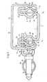
- a slide according to the invention there is shown, at the end, a slide according to the invention and there is seen the fixed lower profile 1 of the slide which has substantially in cross section the shape of a U and whose bottom 2 is flat, largely dimensioned so as to allow the fixing of the slide by means of this bottom 2 either directly on the vehicle floor, or by means of a base on the floor considered and this, by all appropriate means (bolts, bolts and nuts, spot welds, etc.).
- the wings 3, 4 of the U forming the lower fixed element of the slide are shaped in their zone 3a, 4a to delimit substantially half-cylinders then the ends 3b, 4b are folded in U outward.
- the lower fold 3c, 4c is produced so as to cause a certain deformation bringing the outer edge of each fold on the vertical axis Z1, Z2 which must serve as a centering axis for the balls placed between the element fixed of the slide and the movable element of the latter.
- zones 3c, 4c excellent resistance to deformation of the lower profile of the slide and very wide support of the balls.
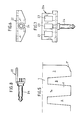
- the folded upper wing 3b ′ is cut to form a toothing 6 of which a developed view has been shown, on a very large scale in FIG. 5, and of which each tooth 7 has a trapezoidal shape extended by a rectangular shape at 7a, which means that the recessed parts 8 have a similar but smaller shape.
- This trapezoidal shape made in the side of the sheet prevents, during the folding of the inverted U (see fig. 1), that the material, by bending and being deformed, fills the toothing with protuberances which would prevent the comb from entering the passage 8.
- Only the end teeth 7 ′ are rounded on their end part to avoid any aggression during handling and various mounting or mounting operations. storage of the raw sides when they come out of the press tools.
- this has in section the shape of an inverted U, the bottom 11 of which is perfectly flat, thus facilitating the fixing, on the upper face of this bottom 11, connecting members of the seat seat frame.
- the bottom 11 is at a sufficient distance from the upper parts of the ends 3b, 4b in U of the lower profile 1.
- the lateral branches 12, 13 of the upper profile are rectilinear up to certain lower zones 12a, 13a, zones in which its ends are shaped as a flattened V whose branches 12b, 12c, 13b, 13c are pressed against each other. the other (see fig. 1) in order to obtain a reinforcement in the lower zone of the upper profile 10 thereby increasing the resistance of the slide in its zone of great efforts and also allowing the positioning of the balls 14 and 15
- these balls are separated by a separating rod 16 visible in FIG. 2 and disposed between two of them placed on the same side of the slide.
- a cimblot 27 is disposed between stroke stops 17, 18 and said balls to prevent them from bursting under the stroke stop shock.
- a lock or comb 22 (see Fig. 6 and 7) consisting of an L-shaped part pierced on its long side 22a with three rectangular openings 23.
- the small wing of the part 22 carries an axis 24 which can pivot in a hole 25 in a lifting beam 26 used for the control of the slide, this lifter 25 being articulated in a bearing 127 secured to the rear part of the upper profile 10 of the slide (see fig. 3).
- the comb 22 is completely free to rotate with respect to the upper profile 10, the teeth 20 of which allow the openings 23 to penetrate towards the teeth 7 carried by the wing 3b ′ of the lower profile 1 of the slide.
- the position of the comb 22 is subjected to the action of a spring 30 (see fig. 1) which tends to penetrate the openings 23 of the comb through the openings 22 of the upper profile 10 and d 'bring at the same time these openings 23 on the teeth 7 of the wing 3b ′ of the lower profile 1 of the slide.
- the spring 30 is a straight spring supported on the outside of the upper profile 10 of the slide.
- the lock When the lifter is released, the lock may be in the position shown in fig. 4 that is to say inclined at a significant angle relative to the horizontal, it therefore regularly engages with at least one of the interstices of the line of teeth 7 of the lower profile 1 and therefore there is always an immediate engagement, avoiding that the comb slides on the top of the teeth.
- a good quality and very fast locking is obtained without there being any possibility of the phenomenon known as "machine gun" occurring.
- the lifter can be replaced by a lever placed on one of the sides of the seat and which controls the two axes 24 carrying the combs 23 by a suitably bent transverse bar.
- the slide therefore has very important resistance qualities due to the conformation in section of the lower 1 and upper 10 profiles, and of a very flexible movement due to the perfect sliding of the balls 14, 15 which are guided in zones of identical support between the upper profile and the lower profile.
- the axis of the balls By causing the axis of the balls to shift relative to the axis of the clearance produced between the two opposite faces of the lower profile 1 and the upper profile 10, this soft and flexible sliding is obtained.
- the floating comb 22 cooperating with teeth of trapezoidal rectangular profile ensures perfect anchoring of the upper profile 10 relative to the lower fixed profile 1.
- the thickness of the upper profile 10 is generally less than the thickness of the lower profile 1, it is also possible in certain cases to use for the manufacture of the upper profile 10 a sheet d '' a practically identical thickness. This is generally the case when it comes to high-end vehicle seats to be produced on vehicles traveling at very high speed.
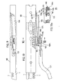
- the upper profile 100 of the slide (see FIGS. 9, 10 and 11) is provided with a control lever produced and having laterally an opening 101 in inverted W having, in its center, two rounded parts 102, 103 which, on the one hand, serve to maintain and, on the other hand, allow the tilting of the floating latch or comb 104 corresponding to the floating latch 22.
- the floating latch 104 has, at its front part, a frame 104a pierced with rectangular openings 104b forming the comb then is extended, at its rear part, by a tail 105 slightly deformed in V (FIG. 9, 11 and 15) in order to match, as much as possible, the free space left between the rounded parts 102, 103 of the opening 101 drilled in the control lever 108 of the slide.
- the tail 105 of the floating latch 104 allows the attachment of a connecting piece 108 substantially affecting the shape of a double inverted clothespin or a flattened Z.
- Part 108a terminated by a hook 109 penetrating a hole 110 in the upper profile 100 of the slide, passes through the tail 105 of the comb or floating latch 104 by holes 120 so that the branches 108a, 108b and 108c of this connecting piece 108 are integral with the tail 105 of the comb 104 and, finally, the end 108c of the connecting piece 108 is hooked by any means of the hoop 121 for controlling the slide.
- this hooking is done using a shaped piece 122 secured, by one of its ends, to the tail 105 and, by its other end, to the rear free part of the arch 121 .
- leaf spring 125 which, by virtue of its arrangement since it is hooked in a lateral protuberance 126 of the profile 100, tends to lower the floating lock in the locking position, by penetration of the comb 104 in the toothing 7 of the lower profile of the slide.
- the assembly is identical to that of FIGS. 9 to 16 but the connecting piece 150 has in its central zone 151 first a fold 150a at right angles to 180 ° and, in its opposite zone, a fold 150b substantially 360 ° in order to allow easy mounting on a hoop 160 which is articulated on the rear end 161 of the comb 104.
- the end 150c of the connecting piece 150 makes the hoop 160 integral with the end 161 of the latch 104.
- a leaf spring 162, disposed at the rear of this connecting piece and whose mounting is identical to the leaf spring 125, allows the introduction of the comb between the teeth 7 of the lower profile 1 of the slide.
Landscapes
- Engineering & Computer Science (AREA)
- Aviation & Aerospace Engineering (AREA)
- Transportation (AREA)
- Mechanical Engineering (AREA)
- Seats For Vehicles (AREA)
- Vibration Dampers (AREA)
- Soft Magnetic Materials (AREA)
- Pressure Welding/Diffusion-Bonding (AREA)
- Supports For Pipes And Cables (AREA)
- Machines For Laying And Maintaining Railways (AREA)
- Control Of Vehicles With Linear Motors And Vehicles That Are Magnetically Levitated (AREA)
- Toys (AREA)
- Casting Support Devices, Ladles, And Melt Control Thereby (AREA)
- Sampling And Sample Adjustment (AREA)
- Respiratory Apparatuses And Protective Means (AREA)
- Piezo-Electric Or Mechanical Vibrators, Or Delay Or Filter Circuits (AREA)
- Electrotherapy Devices (AREA)
- Thermistors And Varistors (AREA)
Priority Applications (1)
| Application Number | Priority Date | Filing Date | Title |
|---|---|---|---|
| AT89403043T ATE71889T1 (de) | 1988-11-10 | 1989-11-06 | Schienenprofil, welches die realisierung von schienen mit schwimmend gelagerter verriegelung gestattet. |
Applications Claiming Priority (2)
| Application Number | Priority Date | Filing Date | Title |
|---|---|---|---|
| FR8814697 | 1988-11-10 | ||
| FR8814697A FR2638797B1 (fr) | 1988-11-10 | 1988-11-10 | Profil de glissieres permettant la realisation de glissieres a verrou flottant |
Publications (2)
| Publication Number | Publication Date |
|---|---|
| EP0368735A1 true EP0368735A1 (de) | 1990-05-16 |
| EP0368735B1 EP0368735B1 (de) | 1992-01-22 |
Family
ID=9371769
Family Applications (1)
| Application Number | Title | Priority Date | Filing Date |
|---|---|---|---|
| EP89403043A Expired - Lifetime EP0368735B1 (de) | 1988-11-10 | 1989-11-06 | Schienenprofil, welches die Realisierung von Schienen mit schwimmend gelagerter Verriegelung gestattet |
Country Status (11)
| Country | Link |
|---|---|
| US (1) | US4950088A (de) |
| EP (1) | EP0368735B1 (de) |
| JP (1) | JP2833800B2 (de) |
| KR (1) | KR960012610B1 (de) |
| AT (1) | ATE71889T1 (de) |
| BR (1) | BR8905767A (de) |
| CA (1) | CA2002509C (de) |
| DE (1) | DE68900763D1 (de) |
| ES (1) | ES2028462T3 (de) |
| FR (1) | FR2638797B1 (de) |
| PT (1) | PT92214B (de) |
Cited By (5)
| Publication number | Priority date | Publication date | Assignee | Title |
|---|---|---|---|---|
| EP0543317A1 (de) * | 1991-11-21 | 1993-05-26 | ELCAT S.p.A. | Vorrichtung zum Längsverstellen von Kraftfahrzeugsitzen |
| WO1993010996A1 (en) * | 1991-12-02 | 1993-06-10 | Rosdon Engineering & Manufacturing Pty. Ltd. | Vehicle seat suspension unit |
| EP0582773A1 (de) * | 1992-07-20 | 1994-02-16 | BERTRAND FAURE Ltd. | Verriegelungsmechanismus für die Gleitschienen eines Kraftfahrzeugsitzes |
| FR2732279A1 (fr) * | 1995-03-31 | 1996-10-04 | Faure Bertrand Equipements Sa | Glissiere de siege de vehicule |
| FR2767096A1 (fr) * | 1997-08-05 | 1999-02-12 | Faure Bertrand Equipements Sa | Glissiere pour siege de vehicules automobiles, comportant un verrou constitue d'une lame elastiquement flexible |
Families Citing this family (4)
| Publication number | Priority date | Publication date | Assignee | Title |
|---|---|---|---|---|
| US5222814A (en) * | 1992-09-30 | 1993-06-29 | Rockwell International Corporation | Vehicle seat track assembly |
| US5465941A (en) * | 1993-06-04 | 1995-11-14 | Abbott; Joshua B. | Fence slat locking system and method |
| US5741000A (en) * | 1995-09-13 | 1998-04-21 | Atoma International, Inc. | Vehicle seat track assembly |
| US7029072B1 (en) | 2002-03-11 | 2006-04-18 | Wirtgen America, Inc. | Modified rumble strip cutter |
Citations (4)
| Publication number | Priority date | Publication date | Assignee | Title |
|---|---|---|---|---|
| US3661352A (en) * | 1969-07-10 | 1972-05-09 | Teleflex Ltd | Adjustable slide members, especially to accomodate vehicle seat travel |
| FR2385928A1 (fr) * | 1977-03-30 | 1978-10-27 | Hammerstein Gmbh C Rob | Dispositif d'immobilisation pour guide de glissieres coulissantes |
| WO1986000857A1 (fr) * | 1984-07-26 | 1986-02-13 | Schweizerische Aluminium Ag | Dispositif de support d'un siege coulissant dans un vehicule |
| US4726617A (en) * | 1986-03-11 | 1988-02-23 | Nissan Motor Co., Ltd. | Adjustable vehicle seat mounting |
Family Cites Families (4)
| Publication number | Priority date | Publication date | Assignee | Title |
|---|---|---|---|---|
| US3759587A (en) * | 1971-12-13 | 1973-09-18 | Faure Bertrand Ets | Slides especially for vehicle seats |
| US4487459A (en) * | 1983-07-01 | 1984-12-11 | General Motors Corporation | Seat slide structure |
| JPS60199742A (ja) * | 1984-03-23 | 1985-10-09 | Fuji Kiko Co Ltd | シ−トリフタ |
| US4787756A (en) * | 1988-02-26 | 1988-11-29 | General Motors Corporation | Apparatus and method of seat adjuster slide |
-
1988
- 1988-11-10 FR FR8814697A patent/FR2638797B1/fr not_active Expired - Fee Related
-
1989
- 1989-11-06 ES ES198989403043T patent/ES2028462T3/es not_active Expired - Lifetime
- 1989-11-06 DE DE8989403043T patent/DE68900763D1/de not_active Expired - Fee Related
- 1989-11-06 EP EP89403043A patent/EP0368735B1/de not_active Expired - Lifetime
- 1989-11-06 AT AT89403043T patent/ATE71889T1/de not_active IP Right Cessation
- 1989-11-07 PT PT92214A patent/PT92214B/pt not_active IP Right Cessation
- 1989-11-07 US US07/432,640 patent/US4950088A/en not_active Expired - Lifetime
- 1989-11-08 CA CA002002509A patent/CA2002509C/en not_active Expired - Fee Related
- 1989-11-09 JP JP1292104A patent/JP2833800B2/ja not_active Expired - Fee Related
- 1989-11-10 BR BR898905767A patent/BR8905767A/pt not_active Application Discontinuation
- 1989-11-10 KR KR1019890016312A patent/KR960012610B1/ko not_active Expired - Fee Related
Patent Citations (4)
| Publication number | Priority date | Publication date | Assignee | Title |
|---|---|---|---|---|
| US3661352A (en) * | 1969-07-10 | 1972-05-09 | Teleflex Ltd | Adjustable slide members, especially to accomodate vehicle seat travel |
| FR2385928A1 (fr) * | 1977-03-30 | 1978-10-27 | Hammerstein Gmbh C Rob | Dispositif d'immobilisation pour guide de glissieres coulissantes |
| WO1986000857A1 (fr) * | 1984-07-26 | 1986-02-13 | Schweizerische Aluminium Ag | Dispositif de support d'un siege coulissant dans un vehicule |
| US4726617A (en) * | 1986-03-11 | 1988-02-23 | Nissan Motor Co., Ltd. | Adjustable vehicle seat mounting |
Cited By (6)
| Publication number | Priority date | Publication date | Assignee | Title |
|---|---|---|---|---|
| EP0543317A1 (de) * | 1991-11-21 | 1993-05-26 | ELCAT S.p.A. | Vorrichtung zum Längsverstellen von Kraftfahrzeugsitzen |
| US5524504A (en) * | 1991-11-21 | 1996-06-11 | Elcat S.P.A. | Device for longitudinally adjusting motor vehicle seats |
| WO1993010996A1 (en) * | 1991-12-02 | 1993-06-10 | Rosdon Engineering & Manufacturing Pty. Ltd. | Vehicle seat suspension unit |
| EP0582773A1 (de) * | 1992-07-20 | 1994-02-16 | BERTRAND FAURE Ltd. | Verriegelungsmechanismus für die Gleitschienen eines Kraftfahrzeugsitzes |
| FR2732279A1 (fr) * | 1995-03-31 | 1996-10-04 | Faure Bertrand Equipements Sa | Glissiere de siege de vehicule |
| FR2767096A1 (fr) * | 1997-08-05 | 1999-02-12 | Faure Bertrand Equipements Sa | Glissiere pour siege de vehicules automobiles, comportant un verrou constitue d'une lame elastiquement flexible |
Also Published As
| Publication number | Publication date |
|---|---|
| PT92214B (pt) | 1995-09-12 |
| KR900007654A (ko) | 1990-06-01 |
| EP0368735B1 (de) | 1992-01-22 |
| CA2002509A1 (en) | 1990-05-10 |
| US4950088A (en) | 1990-08-21 |
| FR2638797A1 (fr) | 1990-05-11 |
| CA2002509C (en) | 1992-09-08 |
| DE68900763D1 (de) | 1992-03-05 |
| FR2638797B1 (fr) | 1991-02-08 |
| ATE71889T1 (de) | 1992-02-15 |
| JP2833800B2 (ja) | 1998-12-09 |
| JPH02199335A (ja) | 1990-08-07 |
| KR960012610B1 (ko) | 1996-09-23 |
| ES2028462T3 (es) | 1992-07-01 |
| BR8905767A (pt) | 1990-06-05 |
| PT92214A (pt) | 1990-05-31 |
Similar Documents
| Publication | Publication Date | Title |
|---|---|---|
| EP0925996B1 (de) | Fahrzeugsitzeinheit mit auf Gleitschienen montiertem, abnehmbarem Sitz | |
| EP0931689B1 (de) | Kraftfahrzeugsitz, herausnehmbar, umwendbar und längsverstellbar | |
| EP0752338B1 (de) | Verriegelbare Schiene für Kraftfahrzeugsitze | |
| FR2851211A1 (fr) | Siege rabattable et vehicule comportant un tel siege | |
| FR2601633A1 (fr) | Cadre de dossier pour sieges, notamment pour sieges de vehicules automobiles | |
| CA2221987A1 (fr) | Glissiere verrouillable instantanement | |
| EP1092585A2 (de) | Fahrzeugsitz mit einer Halsschutzvorrichtung bei einem Heckaufprall | |
| FR2556946A1 (fr) | Siege mobile, notamment siege amovible pour vehicule | |
| EP0947380B1 (de) | Auf dem Schienenboden eingebaute Zahnstangenvorrichtung | |
| FR3116771A1 (fr) | Siège de véhicule à assise et dossiers inclinables pour faciliter l’accès aux places arrière | |
| FR2673148A1 (fr) | Siege amovible de vehicule. | |
| EP0368735B1 (de) | Schienenprofil, welches die Realisierung von Schienen mit schwimmend gelagerter Verriegelung gestattet | |
| EP0522939B1 (de) | Geradlinige Winde mit einer Rolle zum Verriegeln zweier mit einander angelenkten Elemente | |
| EP0026510B1 (de) | Vorrichtung zum Überführen eines Körperbehinderten von einem Rollstuhl in ein Kraftfahrzeug | |
| EP0749868B1 (de) | Gelenkverbindung zwischen der Rückenlehne und dem Sitzteil eines Fahrzeugsitzes | |
| FR2810929A1 (fr) | Dispositif d'assise pour vehicule | |
| EP0965478A1 (de) | In Längsrichtung verstellbar Rücksitz in einem Kraftfahrzeuginnenraum | |
| EP2184201A1 (de) | Verstellbarer Sitz für ein Kraftfahrzeug | |
| FR2609948A1 (fr) | Dispositif de verrouillage a inertie pour siege de vehicule | |
| FR2901192A1 (fr) | Glissiere pour siege de vehicule dotee d'un verrou, et siege comportant une telle glissiere | |
| EP2184202B1 (de) | Sitz für ein Kraftfahrzeug | |
| FR2676425A1 (fr) | Bati pour des pieces a stocker de preference en position verticale. | |
| EP4477465A1 (de) | Fahrzeug mit einem rücksitz mit einer nach mindestens vier positionen schwenkbaren rückenlehne | |
| FR2843080A1 (fr) | Securite pour siege de vehicule, rotatif et calable dans au moins deux positions | |
| FR2868740A1 (fr) | Dispositif de fixation d'un siege sur un plancher de vehicule, siege equipe d'un tel dispositif de fixation et vehicule comprenant un tel siege |
Legal Events
| Date | Code | Title | Description |
|---|---|---|---|
| PUAI | Public reference made under article 153(3) epc to a published international application that has entered the european phase |
Free format text: ORIGINAL CODE: 0009012 |
|
| 17P | Request for examination filed |
Effective date: 19891111 |
|
| AK | Designated contracting states |
Kind code of ref document: A1 Designated state(s): AT BE CH DE ES GB GR IT LI LU NL SE |
|
| 17Q | First examination report despatched |
Effective date: 19910227 |
|
| GRAA | (expected) grant |
Free format text: ORIGINAL CODE: 0009210 |
|
| AK | Designated contracting states |
Kind code of ref document: B1 Designated state(s): AT BE CH DE ES GB GR IT LI LU NL SE |
|
| PG25 | Lapsed in a contracting state [announced via postgrant information from national office to epo] |
Ref country code: GR Free format text: LAPSE BECAUSE OF FAILURE TO SUBMIT A TRANSLATION OF THE DESCRIPTION OR TO PAY THE FEE WITHIN THE PRESCRIBED TIME-LIMIT Effective date: 19920122 |
|
| REF | Corresponds to: |
Ref document number: 71889 Country of ref document: AT Date of ref document: 19920215 Kind code of ref document: T |
|
| GBT | Gb: translation of ep patent filed (gb section 77(6)(a)/1977) | ||
| REF | Corresponds to: |
Ref document number: 68900763 Country of ref document: DE Date of ref document: 19920305 |
|
| ITF | It: translation for a ep patent filed | ||
| REG | Reference to a national code |
Ref country code: ES Ref legal event code: FG2A Ref document number: 2028462 Country of ref document: ES Kind code of ref document: T3 |
|
| PGFP | Annual fee paid to national office [announced via postgrant information from national office to epo] |
Ref country code: SE Payment date: 19921117 Year of fee payment: 4 |
|
| PGFP | Annual fee paid to national office [announced via postgrant information from national office to epo] |
Ref country code: AT Payment date: 19921126 Year of fee payment: 4 |
|
| PLBE | No opposition filed within time limit |
Free format text: ORIGINAL CODE: 0009261 |
|
| STAA | Information on the status of an ep patent application or granted ep patent |
Free format text: STATUS: NO OPPOSITION FILED WITHIN TIME LIMIT |
|
| PG25 | Lapsed in a contracting state [announced via postgrant information from national office to epo] |
Ref country code: LU Free format text: LAPSE BECAUSE OF NON-PAYMENT OF DUE FEES Effective date: 19921130 Ref country code: LI Effective date: 19921130 Ref country code: CH Effective date: 19921130 |
|
| PGFP | Annual fee paid to national office [announced via postgrant information from national office to epo] |
Ref country code: NL Payment date: 19921130 Year of fee payment: 4 Ref country code: BE Payment date: 19921130 Year of fee payment: 4 |
|
| 26N | No opposition filed | ||
| REG | Reference to a national code |
Ref country code: CH Ref legal event code: PL |
|
| PG25 | Lapsed in a contracting state [announced via postgrant information from national office to epo] |
Ref country code: AT Effective date: 19931106 |
|
| PG25 | Lapsed in a contracting state [announced via postgrant information from national office to epo] |
Ref country code: SE Effective date: 19931107 |
|
| PG25 | Lapsed in a contracting state [announced via postgrant information from national office to epo] |
Ref country code: BE Effective date: 19931130 |
|
| BERE | Be: lapsed |
Owner name: A. & M. COUSIN ETS COUSIN FRERES Effective date: 19931130 |
|
| PG25 | Lapsed in a contracting state [announced via postgrant information from national office to epo] |
Ref country code: NL Effective date: 19940601 |
|
| NLV4 | Nl: lapsed or anulled due to non-payment of the annual fee | ||
| EUG | Se: european patent has lapsed |
Ref document number: 89403043.6 Effective date: 19940610 |
|
| PGFP | Annual fee paid to national office [announced via postgrant information from national office to epo] |
Ref country code: GB Payment date: 19950926 Year of fee payment: 7 |
|
| PGFP | Annual fee paid to national office [announced via postgrant information from national office to epo] |
Ref country code: ES Payment date: 19951010 Year of fee payment: 7 |
|
| PG25 | Lapsed in a contracting state [announced via postgrant information from national office to epo] |
Ref country code: GB Effective date: 19961106 |
|
| PG25 | Lapsed in a contracting state [announced via postgrant information from national office to epo] |
Ref country code: ES Free format text: LAPSE BECAUSE OF NON-PAYMENT OF DUE FEES Effective date: 19961107 |
|
| GBPC | Gb: european patent ceased through non-payment of renewal fee |
Effective date: 19961106 |
|
| PGFP | Annual fee paid to national office [announced via postgrant information from national office to epo] |
Ref country code: DE Payment date: 19971029 Year of fee payment: 9 |
|
| PG25 | Lapsed in a contracting state [announced via postgrant information from national office to epo] |
Ref country code: DE Free format text: LAPSE BECAUSE OF NON-PAYMENT OF DUE FEES Effective date: 19990901 |
|
| REG | Reference to a national code |
Ref country code: ES Ref legal event code: FD2A Effective date: 19971213 |
|
| PG25 | Lapsed in a contracting state [announced via postgrant information from national office to epo] |
Ref country code: IT Free format text: LAPSE BECAUSE OF NON-PAYMENT OF DUE FEES;WARNING: LAPSES OF ITALIAN PATENTS WITH EFFECTIVE DATE BEFORE 2007 MAY HAVE OCCURRED AT ANY TIME BEFORE 2007. THE CORRECT EFFECTIVE DATE MAY BE DIFFERENT FROM THE ONE RECORDED. Effective date: 20051106 |