EP0543317A1 - Vorrichtung zum Längsverstellen von Kraftfahrzeugsitzen - Google Patents
Vorrichtung zum Längsverstellen von Kraftfahrzeugsitzen Download PDFInfo
- Publication number
- EP0543317A1 EP0543317A1 EP92119584A EP92119584A EP0543317A1 EP 0543317 A1 EP0543317 A1 EP 0543317A1 EP 92119584 A EP92119584 A EP 92119584A EP 92119584 A EP92119584 A EP 92119584A EP 0543317 A1 EP0543317 A1 EP 0543317A1
- Authority
- EP
- European Patent Office
- Prior art keywords
- guide
- fixed
- guides
- mobile
- spring
- Prior art date
- Legal status (The legal status is an assumption and is not a legal conclusion. Google has not performed a legal analysis and makes no representation as to the accuracy of the status listed.)
- Granted
Links
- 229920003023 plastic Polymers 0.000 claims description 6
- 239000004033 plastic Substances 0.000 claims description 6
- 230000006835 compression Effects 0.000 claims 1
- 238000007906 compression Methods 0.000 claims 1
- 230000006837 decompression Effects 0.000 claims 1
- 239000000463 material Substances 0.000 claims 1
- 230000000284 resting effect Effects 0.000 claims 1
- 238000010276 construction Methods 0.000 description 5
- 230000004048 modification Effects 0.000 description 5
- 238000012986 modification Methods 0.000 description 5
- 239000002184 metal Substances 0.000 description 3
- 229910052751 metal Inorganic materials 0.000 description 3
- 230000036316 preload Effects 0.000 description 3
- 238000003780 insertion Methods 0.000 description 2
- 230000037431 insertion Effects 0.000 description 2
- 238000003466 welding Methods 0.000 description 2
- 229910000831 Steel Inorganic materials 0.000 description 1
- NJFMNPFATSYWHB-UHFFFAOYSA-N ac1l9hgr Chemical compound [Fe].[Fe] NJFMNPFATSYWHB-UHFFFAOYSA-N 0.000 description 1
- 230000000694 effects Effects 0.000 description 1
- 230000000452 restraining effect Effects 0.000 description 1
- 230000000717 retained effect Effects 0.000 description 1
- 239000010959 steel Substances 0.000 description 1
Images







Classifications
-
- B—PERFORMING OPERATIONS; TRANSPORTING
- B60—VEHICLES IN GENERAL
- B60N—SEATS SPECIALLY ADAPTED FOR VEHICLES; VEHICLE PASSENGER ACCOMMODATION NOT OTHERWISE PROVIDED FOR
- B60N2/00—Seats specially adapted for vehicles; Arrangement or mounting of seats in vehicles
- B60N2/02—Seats specially adapted for vehicles; Arrangement or mounting of seats in vehicles the seat or part thereof being movable, e.g. adjustable
- B60N2/04—Seats specially adapted for vehicles; Arrangement or mounting of seats in vehicles the seat or part thereof being movable, e.g. adjustable the whole seat being movable
- B60N2/06—Seats specially adapted for vehicles; Arrangement or mounting of seats in vehicles the seat or part thereof being movable, e.g. adjustable the whole seat being movable slidable
- B60N2/08—Seats specially adapted for vehicles; Arrangement or mounting of seats in vehicles the seat or part thereof being movable, e.g. adjustable the whole seat being movable slidable characterised by the locking device
- B60N2/0812—Location of the latch
- B60N2/0825—Location of the latch outside the rail
-
- B—PERFORMING OPERATIONS; TRANSPORTING
- B60—VEHICLES IN GENERAL
- B60N—SEATS SPECIALLY ADAPTED FOR VEHICLES; VEHICLE PASSENGER ACCOMMODATION NOT OTHERWISE PROVIDED FOR
- B60N2/00—Seats specially adapted for vehicles; Arrangement or mounting of seats in vehicles
- B60N2/02—Seats specially adapted for vehicles; Arrangement or mounting of seats in vehicles the seat or part thereof being movable, e.g. adjustable
- B60N2/04—Seats specially adapted for vehicles; Arrangement or mounting of seats in vehicles the seat or part thereof being movable, e.g. adjustable the whole seat being movable
- B60N2/06—Seats specially adapted for vehicles; Arrangement or mounting of seats in vehicles the seat or part thereof being movable, e.g. adjustable the whole seat being movable slidable
- B60N2/07—Slide construction
- B60N2/0702—Slide construction characterised by its cross-section
- B60N2/0705—Slide construction characterised by its cross-section omega-shaped
-
- B—PERFORMING OPERATIONS; TRANSPORTING
- B60—VEHICLES IN GENERAL
- B60N—SEATS SPECIALLY ADAPTED FOR VEHICLES; VEHICLE PASSENGER ACCOMMODATION NOT OTHERWISE PROVIDED FOR
- B60N2/00—Seats specially adapted for vehicles; Arrangement or mounting of seats in vehicles
- B60N2/02—Seats specially adapted for vehicles; Arrangement or mounting of seats in vehicles the seat or part thereof being movable, e.g. adjustable
- B60N2/04—Seats specially adapted for vehicles; Arrangement or mounting of seats in vehicles the seat or part thereof being movable, e.g. adjustable the whole seat being movable
- B60N2/06—Seats specially adapted for vehicles; Arrangement or mounting of seats in vehicles the seat or part thereof being movable, e.g. adjustable the whole seat being movable slidable
- B60N2/07—Slide construction
- B60N2/0702—Slide construction characterised by its cross-section
- B60N2/0715—C or U-shaped
-
- B—PERFORMING OPERATIONS; TRANSPORTING
- B60—VEHICLES IN GENERAL
- B60N—SEATS SPECIALLY ADAPTED FOR VEHICLES; VEHICLE PASSENGER ACCOMMODATION NOT OTHERWISE PROVIDED FOR
- B60N2/00—Seats specially adapted for vehicles; Arrangement or mounting of seats in vehicles
- B60N2/02—Seats specially adapted for vehicles; Arrangement or mounting of seats in vehicles the seat or part thereof being movable, e.g. adjustable
- B60N2/04—Seats specially adapted for vehicles; Arrangement or mounting of seats in vehicles the seat or part thereof being movable, e.g. adjustable the whole seat being movable
- B60N2/06—Seats specially adapted for vehicles; Arrangement or mounting of seats in vehicles the seat or part thereof being movable, e.g. adjustable the whole seat being movable slidable
- B60N2/07—Slide construction
- B60N2/075—Slide construction roller-less
-
- B—PERFORMING OPERATIONS; TRANSPORTING
- B60—VEHICLES IN GENERAL
- B60N—SEATS SPECIALLY ADAPTED FOR VEHICLES; VEHICLE PASSENGER ACCOMMODATION NOT OTHERWISE PROVIDED FOR
- B60N2/00—Seats specially adapted for vehicles; Arrangement or mounting of seats in vehicles
- B60N2/02—Seats specially adapted for vehicles; Arrangement or mounting of seats in vehicles the seat or part thereof being movable, e.g. adjustable
- B60N2/04—Seats specially adapted for vehicles; Arrangement or mounting of seats in vehicles the seat or part thereof being movable, e.g. adjustable the whole seat being movable
- B60N2/06—Seats specially adapted for vehicles; Arrangement or mounting of seats in vehicles the seat or part thereof being movable, e.g. adjustable the whole seat being movable slidable
- B60N2/08—Seats specially adapted for vehicles; Arrangement or mounting of seats in vehicles the seat or part thereof being movable, e.g. adjustable the whole seat being movable slidable characterised by the locking device
- B60N2/0831—Movement of the latch
- B60N2/0862—Movement of the latch sliding
- B60N2/0875—Movement of the latch sliding in a vertical direction
-
- Y—GENERAL TAGGING OF NEW TECHNOLOGICAL DEVELOPMENTS; GENERAL TAGGING OF CROSS-SECTIONAL TECHNOLOGIES SPANNING OVER SEVERAL SECTIONS OF THE IPC; TECHNICAL SUBJECTS COVERED BY FORMER USPC CROSS-REFERENCE ART COLLECTIONS [XRACs] AND DIGESTS
- Y10—TECHNICAL SUBJECTS COVERED BY FORMER USPC
- Y10T—TECHNICAL SUBJECTS COVERED BY FORMER US CLASSIFICATION
- Y10T74/00—Machine element or mechanism
- Y10T74/20—Control lever and linkage systems
- Y10T74/20576—Elements
- Y10T74/20636—Detents
Definitions
- This invention relates to a device for longitudinally adjusting vehicle seats.
- These adjustment systems also usually comprise slider means such as rollers and sliding blocks interposed between the fixed guides and mobile guides to facilitate movement of the seat, and locking means for locking the fixed guides and mobile guides together when adjustment has been effected.
- a safety mechanism In some current devices the movement of the mobile guides is halted by the use of a safety mechanism.
- This mechanism normally consists of a toothed latch fixed to the mobile guide and urged upwards by a spring so that it engages in corresponding toothing on the fixed guide, to lock the seat in position.
- An object of the present invention is to provide a simplified seat locking device which enables the latch component to be dispensed with, by making the spring multi-functional in the sense that by being suitably sized, shaped and fixed, it is able itself to lock the guides together.
- a further object of the invention is to provide a device of simple and reliable construction and of low cost.
- the fixing systems used up to the present time for securely fixing the guides to the seat or to the vehicle floor usually require the guides to have hexagonal nuts or bolts welded to them.
- the assembly of the guides therefore has to be preceded by the welding of the nuts. This welding is a drawback in cost terms, and is avoided by using the device according to the invention.
- a further object of the invention is to provide a mobile guide, the section of which incorporates a series of threaded collars for seat/guide fixing, as a replacement for the traditional hexagonal nuts.
- the present invention provides a new guide and roller configuration, in which these components have a self-centering profile.
- a further object of the invention is to propose a device for longitudinally adjusting motor vehicle seats able to lock the right and left guides independently, and to simultaneously release them.
- a device for longitudinally adjusting motor vehicle seats of the type comprising a pair of fixed guides rigid with the vehicle floor and a pair of mobile guides rigid with the seat and slidable along said fixed guides, characterised in that between at least one fixed guide and the respective mobile guide there is interposed at least one elastically yieldable element rigidly fixed to the mobile guide, said element being configured such that under normal operating conditions it engages in toothing on the fixed guide to lock the mobile guide in position, a manually operated lever being provided with means which act on said elastically yieldable element to disengage it from the toothing on said fixed guide and release the mobile guide.
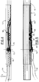
- a fixed guide 10 ad a mobile guide 12 are formed from variously shaped metal section bars, preferably of steel.
- the fixed guide 10 to be fixed to the floor of the vehicle passenger compartment, has a U-shaped cross-section with its edges bent inwards to form a pair of roundish spines 14. These act as support and slide surfaces for two sets of self-centering rollers 16 which are interposed between the mobile guide and fixed guide to facilitate the movement of the one relative to the other.
- the rollers 16 have a cylindrical central region 18 of narrower diameter and two opposing frusto-conical portions 20, to match the shape of two longitudinal projections 22 defined in the mobile ride 12.
- Figure 2 shows a possible modification of the invention in which the fixed guide 10 and mobile guide 12 comprise a pair of spines 11 of suitable opposing V-shape, the rollers 16 assuming the form of two frusto-conical portions 21 joined together by their minor base, to create a particular overall configuration to provide self-centering between the mobile guide and fixed guide, restraining the lateral forces with minimum slack.
- the self-centering rollers 16 can be of either metal or plastics construction.
- rollers facilitate the adjustment of the seat longitudinal position.
- the vertical slack is taken up by suitable plastics blocks 24 mounted on the vertical edges 25 of the mobile guide 12, and preventing iron-iron contact.
- the mobile guide 12 ( Figure 1) is provided with threaded collars 30 arranged centrally along the guide for its fixing to the seat.
- the same arrangement can also be used for the fixed guide.
- the mobile guide 12 no longer comprises the longitudinal projections 20 for rollers.
- the threaded collar 30 faces upwards, enabling the overall height of the guides to be reduced.
- the sliding block 32 is fixed to the mobile guide 12 via two protuberances 34 inserted into through holes 36 suitably provided in the mobile guide.
- the shape of the sliding block 32 determines self-centering relative to the fixed guide 10 by being provided with a slot 38, which accepts the tolerances of the fixed guide and takes up the lateral slack, plus two curved self-centering surfaces 40 which engage the inner edges 42 of the fixed guide 10.
- An arched elastic element or leaf spring 33 preferably of metal construction is fixed to the upper part of the sliding block 32 and has its ends 35 securely anchored to the body of the sliding block. When preloaded, this leaf spring, which can also be formed integrally with the sliding block, takes up the vertical slack when the seat is not in use.
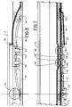
- the guide locking system consists essentially of a latch spring 44, the ends of which are fixed to the mobile guide 12.
- the spring 44 is in the form of a leaf spring, with its central part ( Figure 5) comprising a series of turns or elbows of shape and cross-section chosen on the basis of the resistance to tractive forces required by international regulations.
- the configuration can be round or square, the transverse portions 46 of the spring 44 being inserted between the teeth 48 of the fixed guide 10 and the teeth 50 of the mobile guide 12, to lock them in position.
- the release lever 54 is provided at its two ends with horizontal lugs 58 urged upwards by respective return springs 60 fixed at one, end to the right and left mobile guides.
- the purpose of the springs 60 is to return the lever 54 to its rest position when the adjustment has been made and the guides locked.
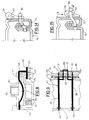
- the spring latch 62 has its ends 63 and 64 embedded in the vertical wall 65 of the mobile guide 12.
- the spring 62 passes transversely through the mobile guide by way of two transverse portions 66, emerges from the mobile guide through slots 67 and then proceeds downwards by way of two vertical portions 68, which are joined together by an elbow portion 69.
- This portion is inserted between the teeth 71 of the fixed guide 10 and the teeth 72 of the mobile guide 12, in a manner analogous to that already described.
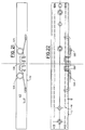
- Plastics sliding blocks (Figure 11) can be used as the sliding means with the system using the spring latch shown in Figures 8-11, with the further advantage of reduced vertical guide dimensions.
- both sides of the spring latch 162 are provided with elbow portions 169 designed to insert between the teeth 171 of the fixed guide 10 and the teeth 172 of the mobile guide 12 on either sides of the guides so as to guarantee further locking actions.
- Two vertical portions 168 connect the elbow portions 169 to a single transverse portion 166.
- the end 163 of the spring latch 162 is fixed to the mobile guide 12.
- the spring latch can alternatively be split into two equal parts 80 ( Figure 12).
- the springs 80 are normally inserted preloaded into the locking position (as can be seen in Figure 14, which represents a section through Figure 13). Withdrawal is achieved by the release lever which, on being rotated in known manner, inserts a cam-shaped or inclined-plane part 57 of the comb 56 between the mobile guide and the spring. During the lowering stage ( Figure 15, arrow B) the part 57 withdraws the spring 80 outwards ( Figure 15, arrow C) to release it from the fixed guide.
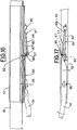
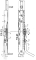
- FIG. 16 and 17 A further alternative embodiment of the present invention is shown in Figures 16 and 17.
- a single spring latch is shaped and fixed to the mobile guide in such a manner as to present double-direction preloading, namely horizontal for locking the guides and vertical for returning the release lever to its rest position when the adjustment has been effected.
- the spring latch indicated by 81, is bent to form a substantially horizontal locking elbow 82, inserted with horizontal preload into the locking position, and two consecutive portions 83 and 84 lying in a substantially vertical plane.
- the spring 81 is fixed to the mobile guide 12 by a bridge 85 formed in this latter.
- the end 86 of the portion 84 is inserted under vertical preload into a through hole 87 provided in the inclined-plane part 57 of the release lever 54, for automatic return of the lever.
- a through hole 87 provided in the inclined-plane part 57 of the release lever 54, for automatic return of the lever.
- the inclined-plane part 57 withdraws the portion 83 outwards, to hence disengage the elbow 82 from the fixed guide 10.
- FIG. 18 A further embodiment of the present invention is shown in Figure 18.
- the spring 90 is fixed in a slot 91 in the mobile guide 12, with its transverse portions 92 and 93 retained in the compartments 94 of the fixed guide 10.
- the spring is normally inserted downwards into the locking position under preload.
- this has its ends bent and is fixed against the side wall 65 of the mobile guide 12 by hooks 102 formed in the wall 63 and locking the central longitudinal part 103 of the spring, the ends of the spring forming the insertion elbows 101.
- FIG. 21 and 22 An embodiment of the spring representing a modification of that shown in Figures 4-7 is shown in Figures 21 and 22.
- the springing effect is improved by two loops formed in proximity to the elbow portions 106.
- a block 110 is interposed between the spring 100 and lever 54 and pivoted with a certain clearance on a pin 111 welded to the end of the lever 54 on the centre line of the spring.
- the block 110 can advantageously be previously snap-mounted on the spring 100. Oh raising the release lever the block 110 undergoes rotary translation against the spring, remaining parallel to this latter and causing an equal lowering of the transverse parts 48 of the spring, with the result that all simultaneously engage or disengage the fixed guide.
- a pin 120 able to form a quick connection with a spring clip 121 (shown separately in Figures 25 and 26) which is welded or snap-mounted on the release lever 54.
- the spring clip 121 comprises elastic fins 122 which converge towards the centre of the seat to firstly facilitate the mounting of the spring clip onto the pin, and then to close onto the pin and prevent its withdrawal.
- the present invention therefore provides an extremely simple locking system comprising a small number of components which are of rapid construction and assembly and of low cost.
Landscapes
- Engineering & Computer Science (AREA)
- Aviation & Aerospace Engineering (AREA)
- Transportation (AREA)
- Mechanical Engineering (AREA)
- Seats For Vehicles (AREA)
- Body Structure For Vehicles (AREA)
- Lighting Device Outwards From Vehicle And Optical Signal (AREA)
- Rear-View Mirror Devices That Are Mounted On The Exterior Of The Vehicle (AREA)
- Vehicle Step Arrangements And Article Storage (AREA)
- Control Of Direct Current Motors (AREA)
Applications Claiming Priority (2)
| Application Number | Priority Date | Filing Date | Title |
|---|---|---|---|
| ITTO910893A IT1250346B (it) | 1991-11-21 | 1991-11-21 | Dispositivo di regolazione longitudinale dei sedili di autoveicoli. |
| ITTO910893 | 1991-11-21 |
Publications (2)
| Publication Number | Publication Date |
|---|---|
| EP0543317A1 true EP0543317A1 (de) | 1993-05-26 |
| EP0543317B1 EP0543317B1 (de) | 1995-09-06 |
Family
ID=11409731
Family Applications (1)
| Application Number | Title | Priority Date | Filing Date |
|---|---|---|---|
| EP92119584A Expired - Lifetime EP0543317B1 (de) | 1991-11-21 | 1992-11-17 | Vorrichtung zum Längsverstellen von Kraftfahrzeugsitzen |
Country Status (9)
| Country | Link |
|---|---|
| US (1) | US5524504A (de) |
| EP (1) | EP0543317B1 (de) |
| JP (1) | JPH07195964A (de) |
| AT (1) | ATE127406T1 (de) |
| DE (1) | DE69204624T2 (de) |
| DK (1) | DK0543317T3 (de) |
| ES (1) | ES2080418T3 (de) |
| GR (1) | GR3018328T3 (de) |
| IT (1) | IT1250346B (de) |
Cited By (5)
| Publication number | Priority date | Publication date | Assignee | Title |
|---|---|---|---|---|
| FR2732279A1 (fr) * | 1995-03-31 | 1996-10-04 | Faure Bertrand Equipements Sa | Glissiere de siege de vehicule |
| US5741000A (en) * | 1995-09-13 | 1998-04-21 | Atoma International, Inc. | Vehicle seat track assembly |
| EP1029733A4 (de) * | 1998-09-16 | 2001-12-05 | Toyo Seat Co Ltd | Sitzgleitschiene für einen fahrersitz |
| CN103260943A (zh) * | 2010-12-13 | 2013-08-21 | 白木工业株式会社 | 车辆用滑动轨道装置 |
| CN104245411A (zh) * | 2012-10-24 | 2014-12-24 | 白木工业株式会社 | 车辆用滑动轨道装置 |
Families Citing this family (26)
| Publication number | Priority date | Publication date | Assignee | Title |
|---|---|---|---|---|
| ITTO980278A1 (it) * | 1998-03-31 | 1999-10-01 | Sergio Gallo | Dispositivo di regolazione longitudinale per sedili di autoviecoli. |
| US6322035B1 (en) * | 1999-01-04 | 2001-11-27 | Dura Global Technologies | Seat track with zero chuck lock |
| WO2001028807A1 (en) | 1999-10-19 | 2001-04-26 | Magna Seating Systems Inc. | Seat track assembly having a locking mechanism with infinite engagement |
| WO2003064203A1 (en) * | 2002-01-28 | 2003-08-07 | Intier Automotive, Inc. | Automotive seat track having vertically adjustable bearings |
| AU2003237165A1 (en) * | 2002-05-03 | 2003-11-17 | Intier Automotive Inc. | Internal reinforcement bracket for a seat track assembly |
| FR2846918B1 (fr) * | 2002-11-13 | 2005-02-04 | Faurecia Sieges Automobile | Glissiere pour siege de vehicule |
| CA2637494A1 (en) * | 2006-02-27 | 2007-08-30 | Intier Automotive Inc. | Leaf spring track latch |
| US20080252126A1 (en) * | 2007-04-10 | 2008-10-16 | Lear Corporation | Power actuated easy entry seat |
| JP5467746B2 (ja) * | 2008-09-12 | 2014-04-09 | シロキ工業株式会社 | シートスライド装置 |
| JP5566014B2 (ja) * | 2008-08-07 | 2014-08-06 | シロキ工業株式会社 | シートトラック装置 |
| US8646742B2 (en) | 2008-07-02 | 2014-02-11 | Shiroki Corporation | Seat rail device |
| JP5461797B2 (ja) * | 2008-07-08 | 2014-04-02 | シロキ工業株式会社 | シートトラック装置 |
| JP5545835B2 (ja) * | 2010-04-28 | 2014-07-09 | シロキ工業株式会社 | 車両用スライドレール装置 |
| JP5662070B2 (ja) | 2010-07-22 | 2015-01-28 | シロキ工業株式会社 | 車両用スライドレール装置 |
| FR2973747B1 (fr) * | 2011-04-05 | 2013-05-03 | Faurecia Sieges Automobile | Entretoise et profile pour glissiere de siege de vehicule automobile |
| JP2013023039A (ja) * | 2011-07-19 | 2013-02-04 | Aisin Seiki Co Ltd | シートスライド装置 |
| JP5650180B2 (ja) | 2012-10-05 | 2015-01-07 | シロキ工業株式会社 | 車両用スライドレール装置 |
| JP6410942B2 (ja) * | 2014-12-12 | 2018-10-24 | アディエント ルクセンブルク ホールディング エス.エー アール.エル. | 車両シート用前後方向アジャスター、及び車両シート |
| WO2017021427A1 (de) * | 2015-08-03 | 2017-02-09 | Johnson Controls Gmbh | Anschlag für eine schiene eines längsverschiebbaren sitzes |
| US9592756B1 (en) | 2015-10-13 | 2017-03-14 | Toyota Motor Engineering & Manufacturing North America, Inc. | Seat assemblies for vehicles |
| US10926667B2 (en) * | 2018-05-04 | 2021-02-23 | Lear Corporation | Track assembly |
| US12233756B2 (en) | 2018-05-04 | 2025-02-25 | Lear Corporation | Track system with a support member |
| US11807142B2 (en) | 2019-03-06 | 2023-11-07 | Lear Corporation | Electrical track assembly |
| DE102021104018B4 (de) | 2020-02-21 | 2023-11-09 | Lear Corporation | Schienensystem mit einem Stützelement, Verfahren zum Betreiben eines Schienensystems |
| US11906028B2 (en) | 2020-02-21 | 2024-02-20 | Lear Corporation | Track system with a support member |
| US11505141B2 (en) | 2020-10-23 | 2022-11-22 | Lear Corporation | Electrical system with track assembly and support assembly |
Citations (7)
| Publication number | Priority date | Publication date | Assignee | Title |
|---|---|---|---|---|
| DE3014300A1 (de) * | 1980-04-15 | 1981-10-22 | Adam Opel AG, 6090 Rüsselsheim | Kraftfahrzeugsitz |
| EP0096632A1 (de) * | 1982-06-09 | 1983-12-21 | COMPAGNIE INDUSTRIELLE DE MECANISMES en abrégé C.I.M. Société dite: | Sitzgestell für Kraftfahrzeuge |
| EP0098702A2 (de) * | 1982-07-02 | 1984-01-18 | Ti Cox Limited | Gleitaufbau für einen Fahrzeugsitz |
| FR2562004A1 (fr) * | 1984-03-28 | 1985-10-04 | Tubauto | Glissiere permettant le reglage longitudinal d'un siege pour des vehicules terrestre, nautique et aerien |
| DE3822453A1 (de) * | 1988-07-02 | 1990-01-04 | Storz E A Kg | Verstellschienenanordnung, insbesondere fuer pkw-sitze |
| EP0349918A2 (de) * | 1988-07-02 | 1990-01-10 | E.A. Storz Gmbh & Co. Kg | Verstellschienenanordnung, insbesondere für PKW-Sitze |
| EP0368735A1 (de) * | 1988-11-10 | 1990-05-16 | A. & M. COUSIN Etablissements COUSIN FRERES | Schienenprofil, welches die Realisierung von Schienen mit schwimmend gelagerter Verriegelung gestattet |
Family Cites Families (11)
| Publication number | Priority date | Publication date | Assignee | Title |
|---|---|---|---|---|
| US3930632A (en) * | 1972-12-27 | 1976-01-06 | Nissan Motor Company Limited | Adjustable seat assembly |
| SE436482B (sv) * | 1977-01-22 | 1984-12-17 | Hammerstein Gmbh C Rob | Anordning vid fordonssete med glidskenestyrning |
| JPS57194121A (en) * | 1981-05-22 | 1982-11-29 | Oi Seisakusho Co Ltd | Seat slide of automobile |
| DE3414649A1 (de) * | 1984-04-18 | 1985-10-31 | Adam Opel AG, 6090 Rüsselsheim | Kraftfahrzeugsitz |
| US4730804A (en) * | 1984-10-26 | 1988-03-15 | Honda Giken Kogyo Kabushiki Kaisha | Seat slide rail device |
| US4621867A (en) * | 1985-04-04 | 1986-11-11 | General Motors Corporation | Easy entry seat adjuster |
| JPH065255Y2 (ja) * | 1988-06-30 | 1994-02-09 | 株式会社タチエス | ウォークイン装置付自動車用シート |
| US4881774A (en) * | 1988-11-07 | 1989-11-21 | Bertrand Faure Automobile | Memory seat track assembly for vehicle seat |
| JPH0730420Y2 (ja) * | 1989-04-28 | 1995-07-12 | アイシン精機株式会社 | 車両用シートスライド装置 |
| JPH0455425U (de) * | 1990-09-20 | 1992-05-12 | ||
| US5228659A (en) * | 1992-08-10 | 1993-07-20 | Hoover Universal, Inc. | Vehicle seat assembly with extending seat track trim cover |
-
1991
- 1991-11-21 IT ITTO910893A patent/IT1250346B/it active IP Right Grant
-
1992
- 1992-11-17 DE DE69204624T patent/DE69204624T2/de not_active Expired - Fee Related
- 1992-11-17 EP EP92119584A patent/EP0543317B1/de not_active Expired - Lifetime
- 1992-11-17 AT AT92119584T patent/ATE127406T1/de not_active IP Right Cessation
- 1992-11-17 ES ES92119584T patent/ES2080418T3/es not_active Expired - Lifetime
- 1992-11-17 DK DK92119584.8T patent/DK0543317T3/da active
- 1992-11-20 JP JP4333908A patent/JPH07195964A/ja active Pending
-
1995
- 1995-04-03 US US08/415,755 patent/US5524504A/en not_active Expired - Lifetime
- 1995-12-07 GR GR950403437T patent/GR3018328T3/el unknown
Patent Citations (7)
| Publication number | Priority date | Publication date | Assignee | Title |
|---|---|---|---|---|
| DE3014300A1 (de) * | 1980-04-15 | 1981-10-22 | Adam Opel AG, 6090 Rüsselsheim | Kraftfahrzeugsitz |
| EP0096632A1 (de) * | 1982-06-09 | 1983-12-21 | COMPAGNIE INDUSTRIELLE DE MECANISMES en abrégé C.I.M. Société dite: | Sitzgestell für Kraftfahrzeuge |
| EP0098702A2 (de) * | 1982-07-02 | 1984-01-18 | Ti Cox Limited | Gleitaufbau für einen Fahrzeugsitz |
| FR2562004A1 (fr) * | 1984-03-28 | 1985-10-04 | Tubauto | Glissiere permettant le reglage longitudinal d'un siege pour des vehicules terrestre, nautique et aerien |
| DE3822453A1 (de) * | 1988-07-02 | 1990-01-04 | Storz E A Kg | Verstellschienenanordnung, insbesondere fuer pkw-sitze |
| EP0349918A2 (de) * | 1988-07-02 | 1990-01-10 | E.A. Storz Gmbh & Co. Kg | Verstellschienenanordnung, insbesondere für PKW-Sitze |
| EP0368735A1 (de) * | 1988-11-10 | 1990-05-16 | A. & M. COUSIN Etablissements COUSIN FRERES | Schienenprofil, welches die Realisierung von Schienen mit schwimmend gelagerter Verriegelung gestattet |
Cited By (9)
| Publication number | Priority date | Publication date | Assignee | Title |
|---|---|---|---|---|
| FR2732279A1 (fr) * | 1995-03-31 | 1996-10-04 | Faure Bertrand Equipements Sa | Glissiere de siege de vehicule |
| US5741000A (en) * | 1995-09-13 | 1998-04-21 | Atoma International, Inc. | Vehicle seat track assembly |
| EP1029733A4 (de) * | 1998-09-16 | 2001-12-05 | Toyo Seat Co Ltd | Sitzgleitschiene für einen fahrersitz |
| CN103260943A (zh) * | 2010-12-13 | 2013-08-21 | 白木工业株式会社 | 车辆用滑动轨道装置 |
| EP2653340A4 (de) * | 2010-12-13 | 2015-04-22 | Shiroki Corp | Gleitschienenvorrichtung für ein fahrzeug |
| US9145070B2 (en) | 2010-12-13 | 2015-09-29 | Shiroki Corporation | Slide rail device for vehicle |
| CN103260943B (zh) * | 2010-12-13 | 2016-01-06 | 白木工业株式会社 | 车辆用滑动轨道装置 |
| CN104245411A (zh) * | 2012-10-24 | 2014-12-24 | 白木工业株式会社 | 车辆用滑动轨道装置 |
| CN104245411B (zh) * | 2012-10-24 | 2017-03-01 | 白木工业株式会社 | 车辆用滑动轨道装置 |
Also Published As
| Publication number | Publication date |
|---|---|
| ITTO910893A1 (it) | 1993-05-21 |
| EP0543317B1 (de) | 1995-09-06 |
| US5524504A (en) | 1996-06-11 |
| DE69204624T2 (de) | 1996-04-18 |
| ITTO910893A0 (it) | 1991-11-21 |
| DK0543317T3 (da) | 1996-01-22 |
| GR3018328T3 (en) | 1996-03-31 |
| JPH07195964A (ja) | 1995-08-01 |
| ATE127406T1 (de) | 1995-09-15 |
| ES2080418T3 (es) | 1996-02-01 |
| DE69204624D1 (de) | 1995-10-12 |
| IT1250346B (it) | 1995-04-07 |
Similar Documents
| Publication | Publication Date | Title |
|---|---|---|
| EP0543317B1 (de) | Vorrichtung zum Längsverstellen von Kraftfahrzeugsitzen | |
| EP1492685B1 (de) | Kopfst tze f r einen fahrzeugsitz | |
| US5286076A (en) | Seat slide device | |
| EP0076041A1 (de) | Fahrzeugsitzverstellvorrichtung | |
| US7150441B2 (en) | Runner for a motor vehicle seat | |
| CA2623119A1 (en) | Seat assembly for a vehicle | |
| US3350046A (en) | Seat slide assembly for automotive vehicles | |
| US5785387A (en) | Vehicle seat assembly with position-fixing means | |
| US4043593A (en) | Vehicle seats | |
| EP0209615A1 (de) | Sitzgleiteinrichtung für Autositz | |
| GB1589126A (en) | Vehicle seats | |
| US4666209A (en) | Seat assembly for vehicles | |
| EP0037726A1 (de) | Fahrzeugsitzverstellung | |
| US4817904A (en) | Seat position adjusting mechanism for a vehicle | |
| IE46660B1 (en) | Improvements in or relating to a slide for a vehicle seat,particularly for the seat of an automobile vehicle | |
| CN115803222B (zh) | 具有将止锁元件形状锁合地锁止在止锁位置中的锁止区段的用于车辆座椅的止锁装置 | |
| WO1995017316A1 (en) | Manual adjuster for a vehicle seat | |
| EP0117131A2 (de) | Längsverschiebemechanik für einen Fahrzeugsitz | |
| EP0743220A2 (de) | Gleitschienenführung für Fahrzeugsitze | |
| EP0696250A1 (de) | Vorrichtung zur längseinstellung von fahrzeugsitzen | |
| US6948772B1 (en) | Linear seat recliner for structural seat | |
| DE102021214144B4 (de) | Vorspannelement für ein Schienenpaar einer Sitzlängsverstelleinrichtung und Sitzlängsverstelleinrichtung | |
| EP4366982A1 (de) | Sitzlängsverstelleinrichtung und sitz | |
| DE19842823A1 (de) | Rückhaltesystem für einen in einem Kraftfahrzeug mitgeführten Kindersitz | |
| EP0098702A2 (de) | Gleitaufbau für einen Fahrzeugsitz |
Legal Events
| Date | Code | Title | Description |
|---|---|---|---|
| PUAI | Public reference made under article 153(3) epc to a published international application that has entered the european phase |
Free format text: ORIGINAL CODE: 0009012 |
|
| AK | Designated contracting states |
Kind code of ref document: A1 Designated state(s): AT BE CH DE DK ES FR GB GR IT LI LU NL PT SE |
|
| 17P | Request for examination filed |
Effective date: 19930531 |
|
| 17Q | First examination report despatched |
Effective date: 19940726 |
|
| GRAA | (expected) grant |
Free format text: ORIGINAL CODE: 0009210 |
|
| AK | Designated contracting states |
Kind code of ref document: B1 Designated state(s): AT BE CH DE DK ES FR GB GR IT LI LU NL PT SE |
|
| REF | Corresponds to: |
Ref document number: 127406 Country of ref document: AT Date of ref document: 19950915 Kind code of ref document: T |
|
| REF | Corresponds to: |
Ref document number: 69204624 Country of ref document: DE Date of ref document: 19951012 |
|
| ITF | It: translation for a ep patent filed | ||
| PGFP | Annual fee paid to national office [announced via postgrant information from national office to epo] |
Ref country code: CH Payment date: 19951130 Year of fee payment: 4 |
|
| ET | Fr: translation filed | ||
| REG | Reference to a national code |
Ref country code: DK Ref legal event code: T3 |
|
| REG | Reference to a national code |
Ref country code: ES Ref legal event code: FG2A Ref document number: 2080418 Country of ref document: ES Kind code of ref document: T3 |
|
| REG | Reference to a national code |
Ref country code: CH Ref legal event code: PL |
|
| REG | Reference to a national code |
Ref country code: GR Ref legal event code: FG4A Free format text: 3018328 |
|
| SC4A | Pt: translation is available |
Free format text: 951123 AVAILABILITY OF NATIONAL TRANSLATION |
|
| PLBE | No opposition filed within time limit |
Free format text: ORIGINAL CODE: 0009261 |
|
| STAA | Information on the status of an ep patent application or granted ep patent |
Free format text: STATUS: NO OPPOSITION FILED WITHIN TIME LIMIT |
|
| 26N | No opposition filed | ||
| PGFP | Annual fee paid to national office [announced via postgrant information from national office to epo] |
Ref country code: GB Payment date: 19961025 Year of fee payment: 5 |
|
| PGFP | Annual fee paid to national office [announced via postgrant information from national office to epo] |
Ref country code: PT Payment date: 19961029 Year of fee payment: 5 |
|
| PGFP | Annual fee paid to national office [announced via postgrant information from national office to epo] |
Ref country code: GR Payment date: 19961031 Year of fee payment: 5 |
|
| PGFP | Annual fee paid to national office [announced via postgrant information from national office to epo] |
Ref country code: LU Payment date: 19961101 Year of fee payment: 5 |
|
| PGFP | Annual fee paid to national office [announced via postgrant information from national office to epo] |
Ref country code: SE Payment date: 19961104 Year of fee payment: 5 |
|
| PGFP | Annual fee paid to national office [announced via postgrant information from national office to epo] |
Ref country code: FR Payment date: 19961106 Year of fee payment: 5 |
|
| PGFP | Annual fee paid to national office [announced via postgrant information from national office to epo] |
Ref country code: ES Payment date: 19961115 Year of fee payment: 5 |
|
| PGFP | Annual fee paid to national office [announced via postgrant information from national office to epo] |
Ref country code: NL Payment date: 19961127 Year of fee payment: 5 |
|
| PGFP | Annual fee paid to national office [announced via postgrant information from national office to epo] |
Ref country code: AT Payment date: 19961129 Year of fee payment: 5 Ref country code: DK Payment date: 19961129 Year of fee payment: 5 |
|
| PG25 | Lapsed in a contracting state [announced via postgrant information from national office to epo] |
Ref country code: LI Free format text: LAPSE BECAUSE OF FAILURE TO SUBMIT A TRANSLATION OF THE DESCRIPTION OR TO PAY THE FEE WITHIN THE PRESCRIBED TIME-LIMIT Effective date: 19961130 Ref country code: CH Free format text: LAPSE BECAUSE OF FAILURE TO SUBMIT A TRANSLATION OF THE DESCRIPTION OR TO PAY THE FEE WITHIN THE PRESCRIBED TIME-LIMIT Effective date: 19961130 |
|
| PGFP | Annual fee paid to national office [announced via postgrant information from national office to epo] |
Ref country code: BE Payment date: 19970109 Year of fee payment: 5 |
|
| PGFP | Annual fee paid to national office [announced via postgrant information from national office to epo] |
Ref country code: DE Payment date: 19970129 Year of fee payment: 5 |
|
| PG25 | Lapsed in a contracting state [announced via postgrant information from national office to epo] |
Ref country code: AT Free format text: LAPSE BECAUSE OF NON-PAYMENT OF DUE FEES Effective date: 19971117 Ref country code: LU Free format text: LAPSE BECAUSE OF NON-PAYMENT OF DUE FEES Effective date: 19971117 Ref country code: GB Free format text: LAPSE BECAUSE OF NON-PAYMENT OF DUE FEES Effective date: 19971117 Ref country code: DK Free format text: LAPSE BECAUSE OF NON-PAYMENT OF DUE FEES Effective date: 19971117 |
|
| PG25 | Lapsed in a contracting state [announced via postgrant information from national office to epo] |
Ref country code: SE Free format text: LAPSE BECAUSE OF NON-PAYMENT OF DUE FEES Effective date: 19971118 Ref country code: ES Free format text: LAPSE BECAUSE OF NON-PAYMENT OF DUE FEES Effective date: 19971118 |
|
| PG25 | Lapsed in a contracting state [announced via postgrant information from national office to epo] |
Ref country code: BE Free format text: LAPSE BECAUSE OF NON-PAYMENT OF DUE FEES Effective date: 19971130 Ref country code: GR Free format text: LAPSE BECAUSE OF NON-PAYMENT OF DUE FEES Effective date: 19971130 Ref country code: FR Free format text: THE PATENT HAS BEEN ANNULLED BY A DECISION OF A NATIONAL AUTHORITY Effective date: 19971130 |
|
| BERE | Be: lapsed |
Owner name: ELCAT S.P.A. Effective date: 19971130 |
|
| PG25 | Lapsed in a contracting state [announced via postgrant information from national office to epo] |
Ref country code: PT Free format text: LAPSE BECAUSE OF NON-PAYMENT OF DUE FEES Effective date: 19980531 |
|
| PG25 | Lapsed in a contracting state [announced via postgrant information from national office to epo] |
Ref country code: NL Free format text: LAPSE BECAUSE OF NON-PAYMENT OF DUE FEES Effective date: 19980601 |
|
| GBPC | Gb: european patent ceased through non-payment of renewal fee |
Effective date: 19971117 |
|
| PG25 | Lapsed in a contracting state [announced via postgrant information from national office to epo] |
Ref country code: DE Free format text: LAPSE BECAUSE OF NON-PAYMENT OF DUE FEES Effective date: 19980801 |
|
| EUG | Se: european patent has lapsed |
Ref document number: 92119584.8 |
|
| NLV4 | Nl: lapsed or anulled due to non-payment of the annual fee |
Effective date: 19980601 |
|
| REG | Reference to a national code |
Ref country code: PT Ref legal event code: MM4A Free format text: LAPSE DUE TO NON-PAYMENT OF FEES Effective date: 19980531 |
|
| REG | Reference to a national code |
Ref country code: FR Ref legal event code: ST |
|
| REG | Reference to a national code |
Ref country code: DK Ref legal event code: EBP |
|
| REG | Reference to a national code |
Ref country code: ES Ref legal event code: FD2A Effective date: 19981212 |
|
| PGFP | Annual fee paid to national office [announced via postgrant information from national office to epo] |
Ref country code: IT Payment date: 20071127 Year of fee payment: 16 |
|
| PG25 | Lapsed in a contracting state [announced via postgrant information from national office to epo] |
Ref country code: IT Free format text: LAPSE BECAUSE OF NON-PAYMENT OF DUE FEES Effective date: 20081117 |