EP0368842B1 - Anbringvorrichtung für weiches material - Google Patents
Anbringvorrichtung für weiches material Download PDFInfo
- Publication number
- EP0368842B1 EP0368842B1 EP87903655A EP87903655A EP0368842B1 EP 0368842 B1 EP0368842 B1 EP 0368842B1 EP 87903655 A EP87903655 A EP 87903655A EP 87903655 A EP87903655 A EP 87903655A EP 0368842 B1 EP0368842 B1 EP 0368842B1
- Authority
- EP
- European Patent Office
- Prior art keywords
- cap
- applicator
- charge
- soft material
- protector member
- Prior art date
- Legal status (The legal status is an assumption and is not a legal conclusion. Google has not performed a legal analysis and makes no representation as to the accuracy of the status listed.)
- Expired - Lifetime
Links
Images


Classifications
-
- B—PERFORMING OPERATIONS; TRANSPORTING
- B43—WRITING OR DRAWING IMPLEMENTS; BUREAU ACCESSORIES
- B43K—IMPLEMENTS FOR WRITING OR DRAWING
- B43K23/00—Holders or connectors for writing implements; Means for protecting the writing-points
- B43K23/08—Protecting means, e.g. caps
- B43K23/10—Protecting means, e.g. caps for pencils
-
- A—HUMAN NECESSITIES
- A45—HAND OR TRAVELLING ARTICLES
- A45D—HAIRDRESSING OR SHAVING EQUIPMENT; EQUIPMENT FOR COSMETICS OR COSMETIC TREATMENTS, e.g. FOR MANICURING OR PEDICURING
- A45D40/00—Casings or accessories specially adapted for storing or handling solid or pasty toiletry or cosmetic substances, e.g. shaving soaps or lipsticks
- A45D40/02—Casings wherein movement of the lipstick or like solid is a sliding movement
- A45D40/04—Casings wherein movement of the lipstick or like solid is a sliding movement effected by a screw
-
- A—HUMAN NECESSITIES
- A45—HAND OR TRAVELLING ARTICLES
- A45D—HAIRDRESSING OR SHAVING EQUIPMENT; EQUIPMENT FOR COSMETICS OR COSMETIC TREATMENTS, e.g. FOR MANICURING OR PEDICURING
- A45D40/00—Casings or accessories specially adapted for storing or handling solid or pasty toiletry or cosmetic substances, e.g. shaving soaps or lipsticks
- A45D40/20—Pencil-like cosmetics; Simple holders for handling stick-shaped cosmetics or shaving soap while in use
-
- A—HUMAN NECESSITIES
- A45—HAND OR TRAVELLING ARTICLES
- A45D—HAIRDRESSING OR SHAVING EQUIPMENT; EQUIPMENT FOR COSMETICS OR COSMETIC TREATMENTS, e.g. FOR MANICURING OR PEDICURING
- A45D40/00—Casings or accessories specially adapted for storing or handling solid or pasty toiletry or cosmetic substances, e.g. shaving soaps or lipsticks
- A45D40/20—Pencil-like cosmetics; Simple holders for handling stick-shaped cosmetics or shaving soap while in use
- A45D40/205—Holders for stick-shaped cosmetics whereby the stick can move axially relative to the holder
-
- A—HUMAN NECESSITIES
- A45—HAND OR TRAVELLING ARTICLES
- A45D—HAIRDRESSING OR SHAVING EQUIPMENT; EQUIPMENT FOR COSMETICS OR COSMETIC TREATMENTS, e.g. FOR MANICURING OR PEDICURING
- A45D40/00—Casings or accessories specially adapted for storing or handling solid or pasty toiletry or cosmetic substances, e.g. shaving soaps or lipsticks
- A45D40/26—Appliances specially adapted for applying pasty paint, e.g. using roller, using a ball
- A45D40/262—Appliances specially adapted for applying pasty paint, e.g. using roller, using a ball using a brush or the like
-
- B—PERFORMING OPERATIONS; TRANSPORTING
- B43—WRITING OR DRAWING IMPLEMENTS; BUREAU ACCESSORIES
- B43K—IMPLEMENTS FOR WRITING OR DRAWING
- B43K21/00—Propelling pencils
- B43K21/02—Writing-core feeding mechanisms
- B43K21/08—Writing-core feeding mechanisms with the writing-cores fed by screws
-
- B—PERFORMING OPERATIONS; TRANSPORTING
- B43—WRITING OR DRAWING IMPLEMENTS; BUREAU ACCESSORIES
- B43K—IMPLEMENTS FOR WRITING OR DRAWING
- B43K29/00—Combinations of writing implements with other articles
- B43K29/06—Combinations of writing implements with other articles with sharpening devices
-
- B—PERFORMING OPERATIONS; TRANSPORTING
- B43—WRITING OR DRAWING IMPLEMENTS; BUREAU ACCESSORIES
- B43L—ARTICLES FOR WRITING OR DRAWING UPON; WRITING OR DRAWING AIDS; ACCESSORIES FOR WRITING OR DRAWING
- B43L23/00—Sharpeners for pencils or leads
-
- A—HUMAN NECESSITIES
- A45—HAND OR TRAVELLING ARTICLES
- A45D—HAIRDRESSING OR SHAVING EQUIPMENT; EQUIPMENT FOR COSMETICS OR COSMETIC TREATMENTS, e.g. FOR MANICURING OR PEDICURING
- A45D40/00—Casings or accessories specially adapted for storing or handling solid or pasty toiletry or cosmetic substances, e.g. shaving soaps or lipsticks
- A45D40/20—Pencil-like cosmetics; Simple holders for handling stick-shaped cosmetics or shaving soap while in use
- A45D40/205—Holders for stick-shaped cosmetics whereby the stick can move axially relative to the holder
- A45D2040/207—Holders for stick-shaped cosmetics whereby the stick can move axially relative to the holder the relative movement being made by an axial action, e.g. by pushing
Definitions
- This invention relates to an applicator for moldable soft materials as for example, soft cosmetics, crayons, marking pens, eye liners, lip liners and the like.
- an applicator which can be used with such soft materials so as to provide a fine point when necessary in a safe manner.
- U.S. 1,0 ⁇ 55,0 ⁇ 28, Flynn and Payne describes a paste cup for delivery of paste to the edges of a cigar wrapper in the manufacture of a cigar.
- the delivery is done by a plunger and orifice.
- U.S. 1,270 ⁇ ,914, Zimdars describes a mechanical pencil with a clutch and spring. Fingers 7 are provided to guard against lead slippage from the clutch.
- U.S. 1,861,466, Bafetti is a crayon holder which is sharpened by a conical shaped thimble sharpening tool F which is snapped on when needed.
- the tool has a cutting or shaving plate f1 which make thin shavings.
- U.S. 2,60 ⁇ 6,527, Filak describes an eyebrow pencil which is self-sharpening. Three or four wires are embedded in the forward portion of the sleeve which act as sharpeners.
- U.S. 2,665,696, Weis is a combination lipstick applicator and sharpener.
- a separate combined cap and sharpener 60 ⁇ is described.
- the interior of the cap has ridges 64 converging towards the closed end of the cap and having an angular conformity to the taper of the lipstick 10 ⁇ .
- the ridges are stated as being “preferably sharp at their edges as shown in 68 in Fig. 8. However, they can be made rounded or blunt to place the taper into a point and may also be curved to conform to a rounded point.” Sharpening is accomplished by pushing the lipstick against the end of the cap and rotating which causes the ridges to act on the lipstick material.
- U.S. 3,0 ⁇ 77,183, Spatz relates to the sharpening of relatively soft material such as eyebrow pencils.
- the patent states that in the sharpening of prior art pencils there is a tendency to clog.
- Springs are provided to bring the point of the marking pencil into operative engagement with a pointer 28.
- Pointer 28 appears to comprise a truncated hollow cone 110 ⁇ having a slot 112, one edge 114 of the slot being defined by the surfaces 115 of a wedge 116.
- Edge 114 is a cutter edge.
- the rotation of the cap causes the pointer to rotate under the action of the spring. The cutter bites into the crayon to cut a chip.
- U.S. 3,232,276, Kupersmith and Zeigler describes an eyebrow pencil and sharpener which is typical of the prior art. It has a barrel 10 ⁇ which houses a feed screw 27. At the end of the feed screw 27 is a crayon supporting thimble 31 which has a socket 32 in which an eyebrow pencil crayon 34 is mounted. What the device accomplishes is that it pushes the crayon into a metal sharpener 39. Although the device has a cap 38, the cap does not participate in the formation of the sharpened end of the crayon.
- French Patent 733,80 ⁇ 0 ⁇ appears to have material protruding through the end of the cap.
- French Patent 919,892 pushes the crayon 1 through the open end of a cap.
- the pencil case is designated as 9, the threads as 11. Although it is not specifically stated it appears that rotation of the cap causes the crayon to project through the end of the cap and be cut by number 12.
- One object of this invention is to provide an applicator which can be used with moldable soft materials so as to provide a fine point in a simple, rapid manner.
- This invention comprises broadly the combination of a body having a chamber with an open front end, and a hollow tip forming cap having an interior conical surface and releasably secured to the body.
- a charge of moldable soft material such as cosmetic eye liner is inserted into the body and forced into the conical surface by a piston or rod until a conical tip is formed.
- the cap is then released from the body exposing a fine point of soft material supported by the body and available for use.
- the interior conical surface and the interior surface of the chamber are sufficiently smooth and non-sticking so that the charge of moldable soft material is freely slidable within said chamber and readily releasable from such conical surface.
- the charge of soft material can be incorporated either directly or as a pre-formed shaped material or housed in a cartridge open at both ends.
- the forcing means can be, but is not limited to, a piston upon which direct pressure is applied or a threaded member movable by rotation and which in turn acts on the charge of soft material.
- BE-A-489,472 discloses a lipstick applicator with a removable protector cap over an opening, at the top of the applicator, through which lipstick may be pushed by a piston means.
- the cap is removed and coupled at the bottom of the applicator with the piston means. The cap is then rotated to drive the piston means and push lipstick through the opening at the top of the applicator.
- FR-A-968,604 and US-A-2 209 849 disclose an applicator for moldable soft material which permits the formation and exposure of a fresh point, comprising: a body having a chamber containing a charge of moldable soft material said body including a front end having an opening communicating with said chamber; a cap which is detachably securable to said front end of said body and which has an interior conical surface which forms a recess therein; and manually actuable pushing means movable within said chamber of said body and in contact with the rear of said charge of soft material for forcing said charge of soft material through said opening in said front end of said body and into said recess of said cap when said cap is secured to said body, the interior surface of said body and said cap each being sufficiently smooth and non-sticking so that said charge of soft material is freely slidable within said chamber of said body and readily releasable from said interior surface of said cap.
- the present invention provides an applicator being characterized by the body having a frusto-conical surface extending about the opening in the front end, and the interior conical surface of the cap including a portion which is registrable in tight fitting relationship with the frusto-conical surface of the body when the cap is secured to the front end of said body, whereby actuation of the pushing means pushes the charge of soft material into the conical recess to form a fresh point on the end of the charge of soft material and detaching of the cap exposes the fresh point.
- an additional or outer protector member is provided which has an interior surface registrable with the exterior surface of the tip forming cap. With medium soft and less creamy materials the outer protector member would not be needed if the interior surface of the tip forming cap is sufficiently smooth and non-sticking as is the case with "Teflon".
- the tip forming cap When used with the outer protector member the tip forming cap has slits which form fingers. Upon release of the outer protector member the tip forming cap is preferably drawn backward to release it from the material and body and then slid forward and removed resulting in the formation of a conical tip of the soft material.
- the tip forming cap has an exterior transverse, circular ridge which registers with the slightly wider interior, transverse circular groove in the outer protector member.
- the tip forming cap is permanently housed in the outer protector member so that release of the outer protector member pulls the tip forming cap with it, opens and closes the fingers and leaves the desired conical tip.
- the interior surfaces of the tip-forming cap and the chamber are sufficiently smooth and non-sticking to permit the charge to be easily slidable and readily releasable. If the tip-forming cap is made of a resilient plastic with a smooth surface, such as nylon and more particularly "Teflon", removal of the protector member permits the fingers to open without sliding back, so that the user may remove the tip forming cap by simply sliding forward which both frees it from the body as well as the material if quick release attachment is used.
- the piston means preferably comprises a threadable cover and rod.
- the protector member is preferably interiorly threaded so as to be firmly attached to the body during the formation of the conical tip of material. As the material point wears out, reconnection of the tip-forming cap and protector member permits the piston to again form a fresh point.
- the tip forming cap has a continuous exterior surface and no slits. After sufficient pressure has been exerted by the piston to fill the hollow space in the tip forming cap, the cap is slid forward and removed, resulting in the formation of a conical tip of the soft material.
- Fig. 1 is a side view of the assembled device made in accordance with one embodiment of this invention.
- Fig. 2 is a cross-section along line 2-2 of Fig.1.
- Fig. 3 is a cross-section along line 3-3 of Fig. 1.
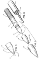
- Fig. 4 is a partial end view of the device where the outer protector member has been removed and the tip forming cap slid back partially to release the fine tip of the material.
- Fig. 5 is an exploded view of the front portion of the device in disassembled fashion.
- Fig. 6 is a view of the rear portion of the device in dissembled fashion.
- Fig. 7 is a side view of the assembled device where no outer protector member is used.
- Fig. 8 is a cross-section along line 7-7 of Fig. 7.
- Fig. 9 is a perspective view of the tip forming cap used without the protector member.
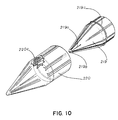
- Fig. 10 is an exploded view of another embodiment of this invention wherein the tip-forming cap has slits but normally is housed and slidable within the protector member.
- the assembled device 10 illustrates an embodiment of this invention which is particularly useful for very soft materials. It comprises the body 11, the tip forming cap 19, the outer threadable protector member 20 and the threadable piston holder 22.
- the piston holder 22 has internal threading 13a which registers with the external threading 13 on body 11 and permits the piston 21 to be inserted and moved forwardly within the chamber of hollow body 11 so as to force material 18 through the opening 17a in the frusto-conical front end 17 of the body 11.
- tip forming cap 19 with slits 19a forming fingers 19b is slid tightly over the frusto-conical front end 17 and then the outer threadable protector member 20 which has interior threading 20a is threaded on to the speed thread 14.
- Tip forming cap 19 has interior threading 16b and a snap notch 16a cooperable with threading 15a and recess 16 in the body 11.
- the piston holder 22 is threaded onto the back thread 13 so that rotation of 22 causes the piston 21 to push the material forward until it is tightly packed.
- the outer protector member 20 is taken off completely and the tip forming cap 19 with its fingers 19b formed by slits 19a is pushed backward so that the conical tip of the material 18 protrudes as shown in Fig. 4. Then the tip forming cap 19 is moved forward and slid off completely leaving the conical tip of material 18 exposed.
- the tip forming cap 119 which has a continuous outer surface and a conical inner surface, is threaded onto the frusto-conical front end 17 of the body 11 but no outer protector member is used.
- the soft material 18 is added to the chamber of body 11 and the piston holder 22 threaded onto the back thread 13 so that rotation of piston holder 22 causes the piston 21 to push the material forward into tip forming cap 119 until it is tightly packed. Then the tip forming cap 119 is unthreaded from front end 17 and moved forward and off, leaving the conical tip of material 18 exposed for use.
- the tip-forming cap 219 has slits 219a forming fingers 219b.
- On its outer surface is a narrow shoulder or circumferential ridge 219c.
- the outer protector member 220 has a circumferential groove 220c on its interior surface. Groove 220c and ridge 219c are registrable with one another, but the groove 220c is wider than the ridge 219c so that when the cap 219 is positioned within the protector member 220 it can slide slightly when the protector member 220 is removed, causing the fingers 219b to open and release the material.
- cap 219 is assembled within the protector member 220, it is normally not removable and is removed when the protector member 220 is removed, so that the user has less pieces to handle.
- the outer protector member 220 and tip forming cap 219 have similar interior threading and notches as the previous embodiment illustrated in Figs 1-6 and attach and detach from the body in a similar manner.
Landscapes
- Coating Apparatus (AREA)
- Pens And Brushes (AREA)
- Mechanical Pencils And Projecting And Retracting Systems Therefor, And Multi-System Writing Instruments (AREA)
Claims (6)
- Anbringvorrichtung für formbares, weiches Material (18), welche die Bildung und Freilegung einer frischen Spitze ermöglicht, enthaltend: einen Grundkörper (11) mit einer Kammer, welche eine Füllung aus dem formbaren, weichen Material (18) enthält, wobei der Grundkörper (11) ein Vorderende (17) mit einer Öffnung (17a) aufweist, die mit der Kammer in Verbindung steht; eine Kappe (19,119,219), welche abnehmbar am Vorderende (17) des Grundkörpers (11) befestigbar ist und eine innere Kegelfläche aufweist, die darin eine Vertiefung bildet; und eine manuell betätigbare Ausdrückeinrichtung (21,22), die innerhalb der Kammer des Grundkörpers (11) und in Berührung mit der Rückseite der Füllung des weichen Materials (18) bewegbar ist, um diese Füllung des weichen Materials (18) durch die Öffnung (17a) am Vorderende (17) des Grundkörpers (11) und in die Vertiefung der Kappe (19,119,219) zu drücken, wenn die Kappe (19,119,219) an dem Grundkörper (11) befestigt ist, wobei die Innenflächen des Grundkörpers (11) und der Kappe (19,119,219) beide ausreichend glatt und nicht-klebend sind, so daß die Füllung des weichen Materials (18) innerhalb der Kammer des Grundkörpers (11) frei gleiten kann und leicht von der Innenfläche der Kappe (19,119,219) lösbar ist, und wobei die Anbringvorrichtung dadurch gekennzeichnet ist, daß der Grundkörper (11) eine kegelstumpfförmige Oberfläche aufweist, die sich rund um die Öffnung (17a) am Vorderende (17) erstreckt, und die innere Kegelfläche der Kappe (19,119,219) einen Bereich aufweist, der dicht anliegend mit der kegelstumpfförmigen Oberfläche des Grundkörpers (17) in Übereinstimmung bringbar ist, wenn die Kappe (19,119,219) am Vorderende (17) des Grundkörpers (11) befestigt wird, wodurch eine Betätigung der Ausdrückeinrichtung (21,22) die Füllung aus weichem Material (18) in die kegelförmige Vertiefung drückt, um am Ende dieser Füllung aus weichem Material (18) eine frische Spitze zu bilden, und wodurch das Entfernen der Kappe (19,119,219) die frische Spitze freilegt.
- Anbringvorrichtung nach Anspruch 1, bei der die Kappe (19,119,219) dazu geeignet ist, mittels zusammenwirkender, am Grundkörper (11) und an der Kappe (19,119,219) angebrachter Gewinde (15a, 16b) abnehmbar am Vorderende (17) des Grundkörpers (11) befestigt zu werden.
- Anbringvorrichtung nach Anspruch 1, bei der die Ausdrückeinrichtung einen beweglich in der Kammer des Grundkörpers (11) gelagerten Kolben (21) und einen mit dem Kolben (21) verbundenen sowie schraubbar am Grundkörper (11) montierten Kolbenhalter (22) aufweist, wodurch eine Drehung des Kolbenhalters (22) den Kolben (21) zu einer Vorwärtsbewegung in der Kammer des Grundkörpers (11) veranlaßt.
- Anbringvorrichtung nach Anspruch 1, bei der die Kappe (19,219) an ihrem Vorderende Finger (19b,219b) bildende Schlitze (19a,219a) aufweist und abnehmbar am Grundkörper (11) befestigt ist, und bei der ein äußeres Schutzteil (20,220) vorgesehen ist, das eine mit der Außenfläche der Kappe (19,219) in Übereinstimmung bringbare Innenfläche aufweist und abnehmbar am Grundkörper (11) befestigt ist.
- Anbringvorrichtung nach Anspruch 4, bei der die Innenfläche des äußeren Schutzteils (220) und die Außenfläche der Kappe (219) zusammenwirkende Einrichtungen (219c,220c) aufweisen, die die Kappe (219) normalerweise im äußeren Schutzteil (220) halten, aber der Kappe (219) erlauben, innerhalb des äußeren Schutzteils (220) geringfügig zu gleiten, um dadurch den Fingern (219b) zu ermöglichen, sich zu öffnen, wenn das Schutzteil (220) vom Grundkörper (11) abgenommen wird.
- Anbringvorrichtung nach Anspruch 5, bei der die zusammenwirkenden Einrichtungen eine Querrippe (219c) auf der Außenfläche der Kappe (219) und eine geringfügig breitere Querrille (220c) in der Innenfläche des äußeren Schutzteils (220) aufweisen.
Priority Applications (1)
| Application Number | Priority Date | Filing Date | Title |
|---|---|---|---|
| AT87903655T ATE117880T1 (de) | 1987-05-22 | 1987-05-22 | Anbringvorrichtung für weiches material. |
Applications Claiming Priority (1)
| Application Number | Priority Date | Filing Date | Title |
|---|---|---|---|
| PCT/US1987/001185 WO1988009267A1 (en) | 1987-05-22 | 1987-05-22 | Applicator for soft materials |
Publications (3)
| Publication Number | Publication Date |
|---|---|
| EP0368842A1 EP0368842A1 (de) | 1990-05-23 |
| EP0368842A4 EP0368842A4 (en) | 1991-03-20 |
| EP0368842B1 true EP0368842B1 (de) | 1995-02-01 |
Family
ID=22202397
Family Applications (1)
| Application Number | Title | Priority Date | Filing Date |
|---|---|---|---|
| EP87903655A Expired - Lifetime EP0368842B1 (de) | 1987-05-22 | 1987-05-22 | Anbringvorrichtung für weiches material |
Country Status (5)
| Country | Link |
|---|---|
| EP (1) | EP0368842B1 (de) |
| JP (1) | JPH02504372A (de) |
| CA (1) | CA1317568C (de) |
| DE (1) | DE3751040T2 (de) |
| WO (1) | WO1988009267A1 (de) |
Families Citing this family (3)
| Publication number | Priority date | Publication date | Assignee | Title |
|---|---|---|---|---|
| DE8806237U1 (de) * | 1988-05-11 | 1988-06-30 | Schwan-Stabilo Schwanhäußer GmbH & Co., 90562 Heroldsberg | Kosmetisches Auftragsgerät |
| DE202004020158U1 (de) * | 2004-12-03 | 2006-01-26 | Schwan-Stabilo Cosmetics Gmbh & Co. Kg | Auftraggerät mit Rückstellsicherung |
| DE502006007629D1 (de) * | 2006-01-24 | 2010-09-23 | Kum Ltd | Spitzer für einen Weichminenstift |
Family Cites Families (14)
| Publication number | Priority date | Publication date | Assignee | Title |
|---|---|---|---|---|
| BE489472A (de) * | ||||
| US1055028A (en) * | 1911-12-16 | 1913-03-04 | Edward C Flynn | Paste-cup. |
| US1270914A (en) * | 1916-06-07 | 1918-07-02 | John B Zimdars | Clutch-pencil. |
| FR733800A (fr) * | 1932-03-17 | 1932-10-11 | Perfectionnement apporté aux porte-mines | |
| US2209849A (en) * | 1939-02-14 | 1940-07-30 | Seguin Maurice | Lipstick holder and sharpener |
| US2559889A (en) * | 1946-05-27 | 1951-07-10 | Richard F Matthews | Lipstick holder |
| US2629889A (en) * | 1947-05-30 | 1953-03-03 | Lengyel Aline | Make-up pencil |
| FR968604A (fr) * | 1948-06-28 | 1950-12-01 | étui distributeur pour rouge à lèvres et produits hygiéniques similaires | |
| US2665696A (en) * | 1950-11-22 | 1954-01-12 | Weis Anthonie Elizabeth | Combination lipstick applicator and sharpener |
| US2979029A (en) * | 1957-10-28 | 1961-04-11 | Melnikoff Zachary | Eyebrow pencil and sharpener therefor |
| US3209730A (en) * | 1963-06-07 | 1965-10-05 | Maybelline Co | Automatic pencil |
| US3232276A (en) * | 1964-06-19 | 1966-02-01 | Maradel Products Inc | Eyebrow pencil and sharpener |
| US3768915A (en) * | 1971-12-06 | 1973-10-30 | Spatz Corp | Axial force limiting cosmetic marking devices |
| JPS60141281U (ja) * | 1984-02-29 | 1985-09-19 | プラチナ萬年筆株式会社 | 筆記具用連結キヤツプ |
-
1987
- 1987-05-22 EP EP87903655A patent/EP0368842B1/de not_active Expired - Lifetime
- 1987-05-22 JP JP62503297A patent/JPH02504372A/ja active Pending
- 1987-05-22 DE DE3751040T patent/DE3751040T2/de not_active Expired - Fee Related
- 1987-05-22 WO PCT/US1987/001185 patent/WO1988009267A1/en not_active Ceased
- 1987-05-26 CA CA000537998A patent/CA1317568C/en not_active Expired - Fee Related
Also Published As
| Publication number | Publication date |
|---|---|
| JPH02504372A (ja) | 1990-12-13 |
| DE3751040T2 (de) | 1995-10-05 |
| EP0368842A1 (de) | 1990-05-23 |
| EP0368842A4 (en) | 1991-03-20 |
| WO1988009267A1 (en) | 1988-12-01 |
| CA1317568C (en) | 1993-05-11 |
| DE3751040D1 (de) | 1995-03-16 |
Similar Documents
| Publication | Publication Date | Title |
|---|---|---|
| US3358699A (en) | Cosmetic storing and dispensing device | |
| US3768915A (en) | Axial force limiting cosmetic marking devices | |
| US5102248A (en) | Applicator for soft materials with tip forming means | |
| US7832108B2 (en) | Pencil sharpener cap | |
| EP0368842B1 (de) | Anbringvorrichtung für weiches material | |
| US2570596A (en) | Holder for cosmetics and the like | |
| US6123476A (en) | Crayon holder with integral sharpener | |
| US20150104233A1 (en) | Shaper | |
| US3502417A (en) | Arrangement for improving the writing properties of fiber-point pens and the like | |
| US2502716A (en) | Lipstick container | |
| US2228812A (en) | Cigarette holder | |
| US2209849A (en) | Lipstick holder and sharpener | |
| JPH06199093A (ja) | 繰り出し式筆記具のキャップ | |
| JPH0240900Y2 (de) | ||
| US4334794A (en) | Self sharpening pencils | |
| GB2252940A (en) | Pencil for cosmetic use or for drawing with sharpener | |
| JP4315380B2 (ja) | 棒状化粧料用削り器 | |
| JPH10174617A (ja) | 繰出し式化粧用ペンシル | |
| US3077183A (en) | Marking pencils | |
| KR200162915Y1 (ko) | 연필캡 기능이 구비된 화장용 연필깎기 | |
| US2941508A (en) | Marking pencil | |
| US2347960A (en) | Device for dispensing molded, compositions | |
| JPH0310899Y2 (de) | ||
| JPH0751359Y2 (ja) | エンピツ削り器 | |
| US2575997A (en) | Cosmetic accessory comprising a rouge cup and a brush |
Legal Events
| Date | Code | Title | Description |
|---|---|---|---|
| PUAI | Public reference made under article 153(3) epc to a published international application that has entered the european phase |
Free format text: ORIGINAL CODE: 0009012 |
|
| 17P | Request for examination filed |
Effective date: 19891127 |
|
| AK | Designated contracting states |
Kind code of ref document: A1 Designated state(s): AT BE CH DE FR GB IT LI LU NL SE |
|
| A4 | Supplementary search report drawn up and despatched |
Effective date: 19910201 |
|
| AK | Designated contracting states |
Kind code of ref document: A4 Designated state(s): AT BE CH DE FR GB IT LI LU NL SE |
|
| 17Q | First examination report despatched |
Effective date: 19921026 |
|
| RAP1 | Party data changed (applicant data changed or rights of an application transferred) |
Owner name: L'IMAGE |
|
| GRAA | (expected) grant |
Free format text: ORIGINAL CODE: 0009210 |
|
| AK | Designated contracting states |
Kind code of ref document: B1 Designated state(s): AT BE CH DE FR GB IT LI LU NL SE |
|
| PG25 | Lapsed in a contracting state [announced via postgrant information from national office to epo] |
Ref country code: IT Free format text: LAPSE BECAUSE OF FAILURE TO SUBMIT A TRANSLATION OF THE DESCRIPTION OR TO PAY THE FEE WITHIN THE PRE;WARNING: LAPSES OF ITALIAN PATENTS WITH EFFECTIVE DATE BEFORE 2007 MAY HAVE OCCURRED AT ANY TIME BEFORE 2007. THE CORRECT EFFECTIVE DATE MAY BE DIFFERENT FROM THE ONE RECORDED.SCRIBED TIME-LIMIT Effective date: 19950201 Ref country code: CH Effective date: 19950201 Ref country code: AT Effective date: 19950201 Ref country code: BE Effective date: 19950201 Ref country code: NL Effective date: 19950201 Ref country code: LI Effective date: 19950201 |
|
| REF | Corresponds to: |
Ref document number: 117880 Country of ref document: AT Date of ref document: 19950215 Kind code of ref document: T |
|
| REF | Corresponds to: |
Ref document number: 3751040 Country of ref document: DE Date of ref document: 19950316 |
|
| ET | Fr: translation filed | ||
| PG25 | Lapsed in a contracting state [announced via postgrant information from national office to epo] |
Ref country code: SE Effective date: 19950501 |
|
| REG | Reference to a national code |
Ref country code: CH Ref legal event code: PL |
|
| PG25 | Lapsed in a contracting state [announced via postgrant information from national office to epo] |
Ref country code: GB Effective date: 19950522 |
|
| PG25 | Lapsed in a contracting state [announced via postgrant information from national office to epo] |
Ref country code: LU Free format text: LAPSE BECAUSE OF NON-PAYMENT OF DUE FEES Effective date: 19950531 |
|
| NLV1 | Nl: lapsed or annulled due to failure to fulfill the requirements of art. 29p and 29m of the patents act | ||
| PLBE | No opposition filed within time limit |
Free format text: ORIGINAL CODE: 0009261 |
|
| STAA | Information on the status of an ep patent application or granted ep patent |
Free format text: STATUS: NO OPPOSITION FILED WITHIN TIME LIMIT |
|
| GBPC | Gb: european patent ceased through non-payment of renewal fee |
Effective date: 19950522 |
|
| 26N | No opposition filed | ||
| PGFP | Annual fee paid to national office [announced via postgrant information from national office to epo] |
Ref country code: FR Payment date: 19970425 Year of fee payment: 11 |
|
| PGFP | Annual fee paid to national office [announced via postgrant information from national office to epo] |
Ref country code: DE Payment date: 19970726 Year of fee payment: 11 |
|
| PG25 | Lapsed in a contracting state [announced via postgrant information from national office to epo] |
Ref country code: FR Free format text: LAPSE BECAUSE OF NON-PAYMENT OF DUE FEES Effective date: 19980531 |
|
| PG25 | Lapsed in a contracting state [announced via postgrant information from national office to epo] |
Ref country code: DE Free format text: LAPSE BECAUSE OF NON-PAYMENT OF DUE FEES Effective date: 19990302 |
|
| REG | Reference to a national code |
Ref country code: FR Ref legal event code: ST |